Roof Design
DESIGN OF ROOF
To design roof with flanges and reinforcement of the car with given skin data and mastersection.
Roof :
Roof is the part of automobile which is fixed top of the compartment which product the vehicle occupants from sunlight, rain, wind and other external factors. While roll-over accidents it product the passengers. So, strength of the roof is very important.
Roof materials :
There are wide range of materials are using such as steel, Aluminium, Thermosetting plastic sheet. In case of steel usual thickness is range of 065 – 0.85mm.
Reinforcement Fixing :
Spot welding and flexible adhesives such as mastic are used to fix reinforcement with roof.
Manufacturing process of Roof :
Deep drawing
It is one of Sheet metal forming process and Widely used Sheet metal forming process.
It is classified into three types depands on load application.
1. Deep drawing using tools.
2. Deep drawing using active media.
3. Deep drawing by means od active energy.
Deep drawing method using tool is mostly used in sheet metal forming.
Deep drawing process
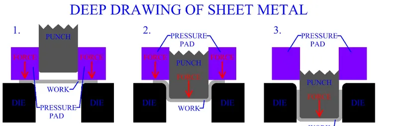
Deep drawing of sheet metal is performed with a punch and die. The punch is the desired shape of the base of the part, once drawn.
The die cavity matches the punch and is a little wider to allow for its passage, as well as clearance.
This setup is similar to sheet metal cutting operations. As in cutting, clearance is the lateral distance between the die edge and the punch edge.
The sheet metal work piece, called a blank, is placed over the die opening. A blankholder, that surrounds the punch, applies pressure to the entire surface of the blank, (except the area under the punch), holding the sheet metal work flat against the die. The punch travels towards the blank. After contacting the work, the punch forces the sheet metal into the die cavity, forming its shape.
Embossing
Sheet metal embossing is a stamping process for producing raised or sunken designs or relief in sheet metal. This process can be made by means of matched male and female roller dies, or by passing sheet or a strip of metal between rolls of the desired pattern. It is often combined with foil stamping to create a shiny, 3D effect.
Embossing process
The metal sheet embossing operation is commonly accomplished with a combination of heat and pressure on the sheet metal, depending on what type of embossing is required.
Metal sheet is drawn through the male and female roller dies, producing a pattern or design on the metal sheet. Depending on the roller dies used, different patterns can be produced on the metal sheet.
Componets of roof :
1. Outer roof.
2. Front roof rails.
3. Rear roof rails.
4. Centre roof rails.
5. Bow roof.
Design of roof :
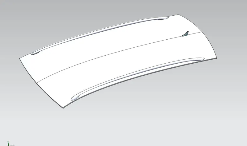
Given Skin data
1. Design of Outer roof panel
- To design outer roof panel inputs given are skin data and master section.
- Flanges in Front and rear are developed using law extensiom, Dimensions are taken from master section.
- To create flanges in side i followed the dimensions of front flange.
- After creating flanges in one side it was replicated into other side using mirror geomentry command.
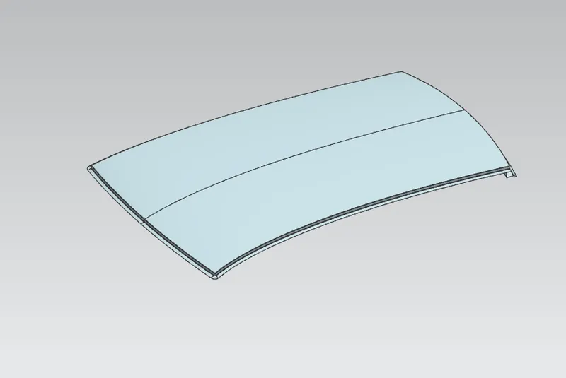
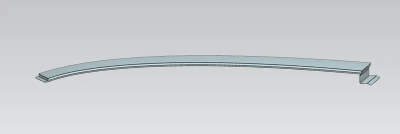
Outer roof panel
2. Design of Front roof rails
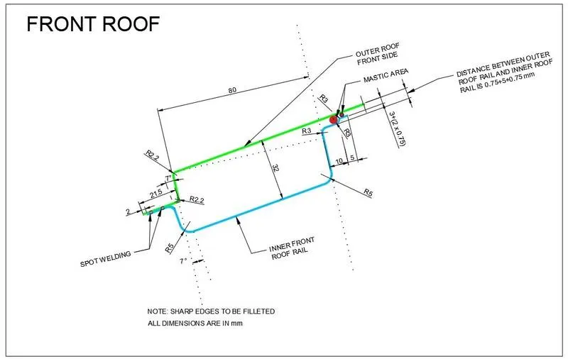
- To design front roof rails dimensions are taken from master section.
- Commands used to design front roof rails are offset surface, law extension and offset curve in face.
- Emboss are created in centre of the front roof rails.
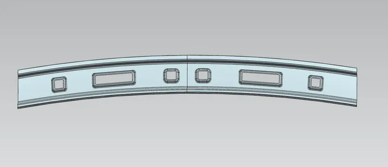
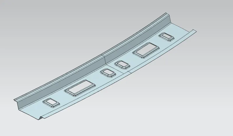
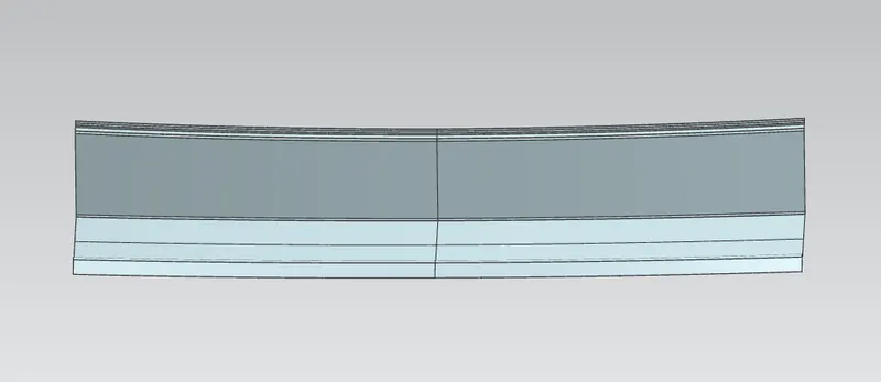
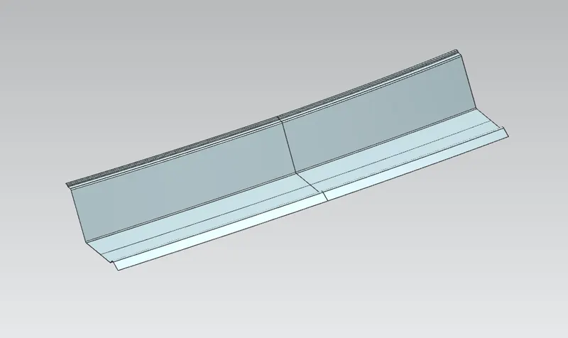
3. Design of rear roof rails
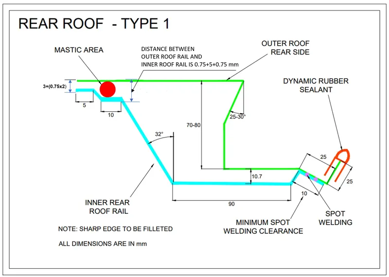
- To design rear roof rails dimensions are taken from master section.
- Command used to design rear roof rails are offse surface, law extension and oddset curve in face.
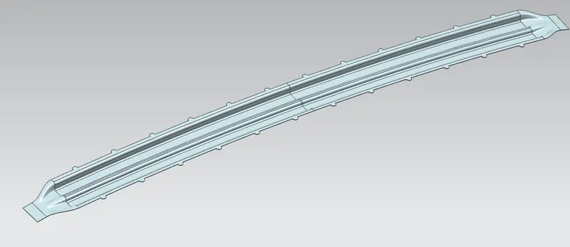
4. Centre roof rails
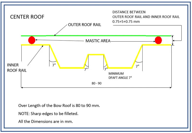
- To design Centre roof rails dimensions are taken from master section.
- Commands used to design centre rails are offset surface,law extenion and offset curve in face.
5. Bow roof
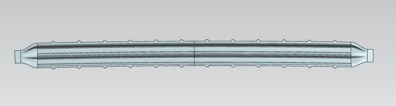
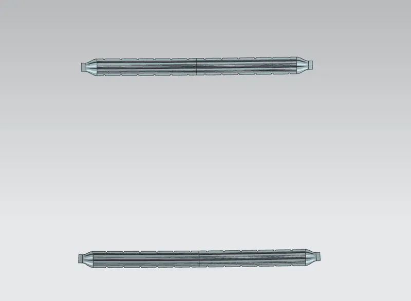
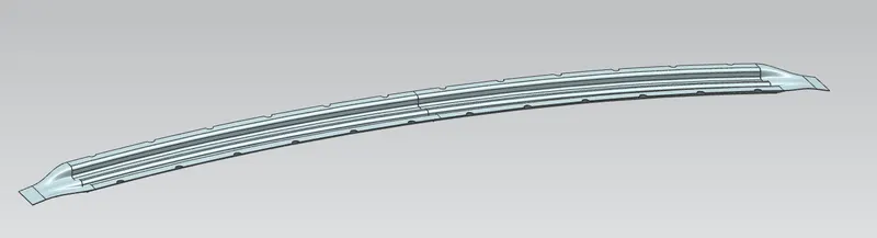
- To design bow roof dimensions are are followed same as centre roof rails.
- I have decides to create two bow roof in two sides of centre roof rails.
Draft Analysis :
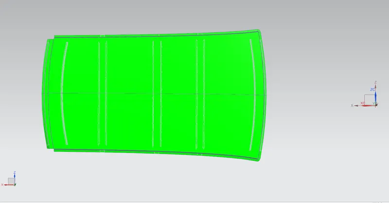
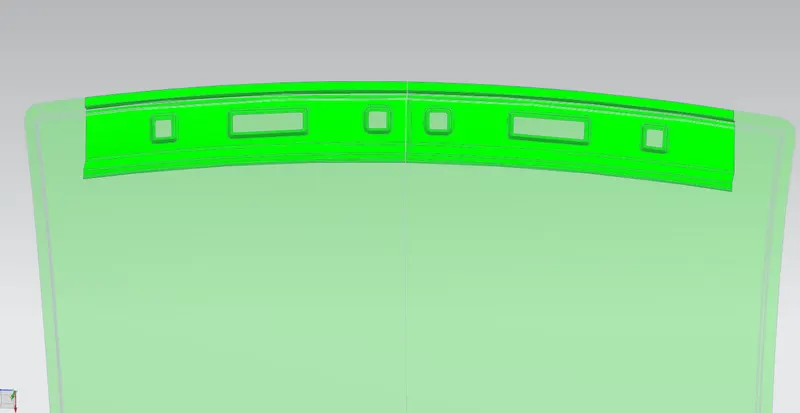
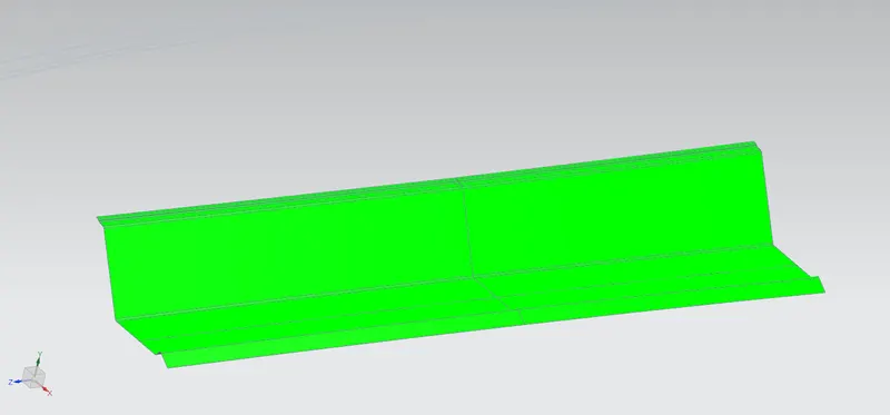
Draft analysis are made on all components of rood. With minimun draft angle of 7 degree . All the parts in green color means all surfaces with minimun draft.
Outer roof panel
Front roof rail
Rear roof rail
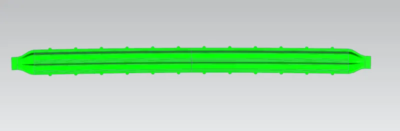
Centre roof rails
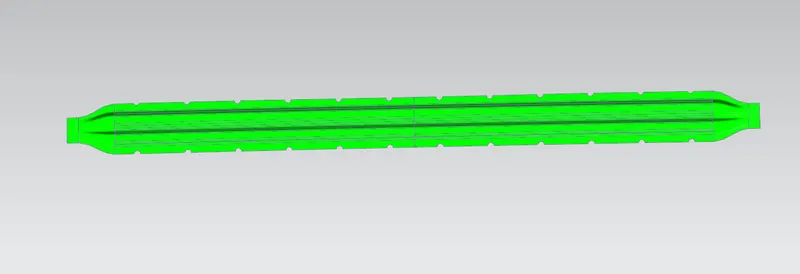
Bow roof 1
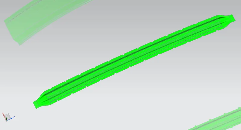
Bow roof 2
Heat distortation calculation :
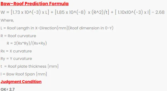
| Section | L | Rx | Ry | Rx *Ry | Rx+Ry | 2*(Rx*Ry/Rx+Ry) | R^2 | t | I | W < or = 2.7 | Result |
| FR to BR 1 | 2028.7 | 5705.3937 | 2036.789 | 11620683.13 | 7742.1827 | 3001.913951 | 9011487.369 | 0.75 | 467.7 | 1.566404355 | Pass |
| BR 1 to CR | 2028.7 | 4865.9646 | 6624.5586 | 32234867.64 | 11490.5232 | 5610.687534 | 31479814.6 | 0.75 | 328.1 | 1.967063094 | Pass |
| CR to BW 2 | 2028.7 | 3985.7442 | 10490.7063 | 41813271.79 | 14476.4505 | 5776.72984 | 33370607.64 | 0.75 | 432.7 | 2.128762655 | Pass |
| BW 2 to RR | 2028.7 | 3298.2705 | 13934.1533 | 45958606.77 | 17232.4238 | 5333.968954 | 28451224.8 | 0.75 | 335.5 | 1.900497878 | Pass |
Snow load Calculation :
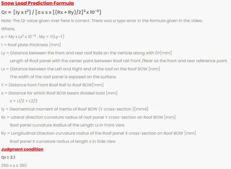
| Section | Iy | t^2 | Y | Ly | Lx | My | a | L1 | L2 | S | Rx | Ry | Rx+Ry | Qr | Result |
| FR to BR 1 | 8.563599775 | 1.5 | 566.5 | 1951.6 | 1099.8 | 784659.15 | 0.9490923529 | 566.5 | 406 | 486.25 | 3264.3798 | 2886.2273 | 6150.6071 | 0.2943090071 | Fail |
| BR 1 to CR | 7.929385 | 1.5 | 972.5 | 1951.6 | 1070.8 | 952174.75 | 1.091775604 | 406 | 511.7 | 458.85 | 2931.59 | 6555.337 | 9486.927 | 0.1055201782 | Fail |
| CR to BW 2 | 8.700538974 | 1.5 | 1484.2 | 1951.6 | 1049.8 | 693715.08 | 0.7645295431 | 511.7 | 467.4 | 489.55 | 6281.9274 | 6038.8492 | 12320.7766 | 0.09188188873 | Fail |
Has the result was failed for Snow load strength of part have to be increased.
To increase the strebgth enboss are created and some extra mastic points are added.
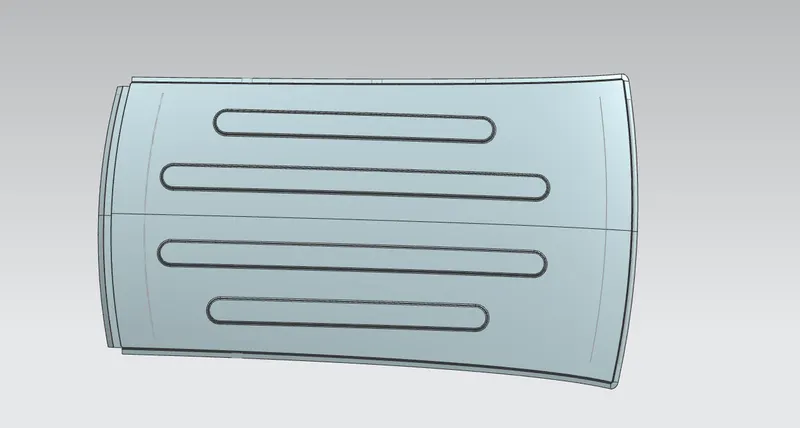
Outer roof panel after improvement
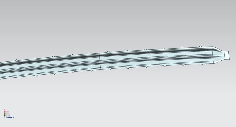
Centre roof rail after improvemet (extra mastic point added)
Conclusion :
Finally design rood has been done by considering all design consideration.