Roof Design
AIM
To design a roof from given class A surface and design Front roof, Rear roof rail, bow rail and centre reinforcement with the help of master section and also to do heat distortion, snow load criteria study for roof.
ROOF
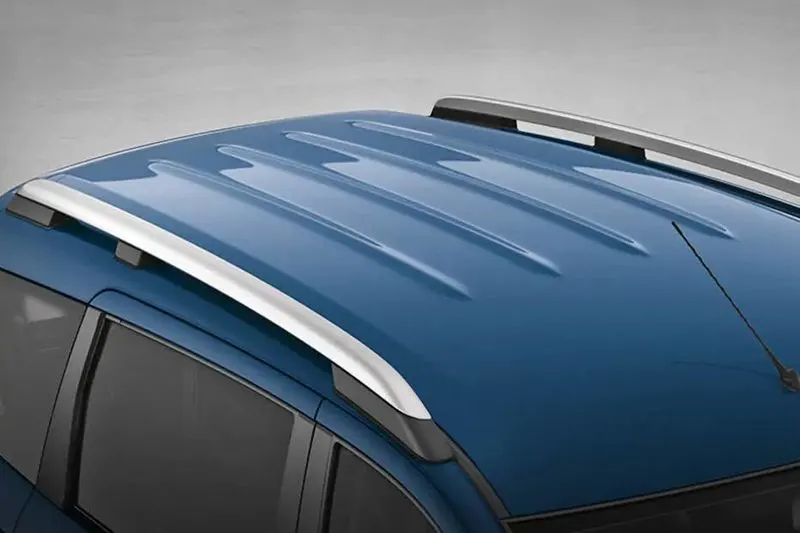
- A roof is a top part of car which is basically use to protect the passenger from rain, sun ,wind ,dust ,snow and other environmental conditions.
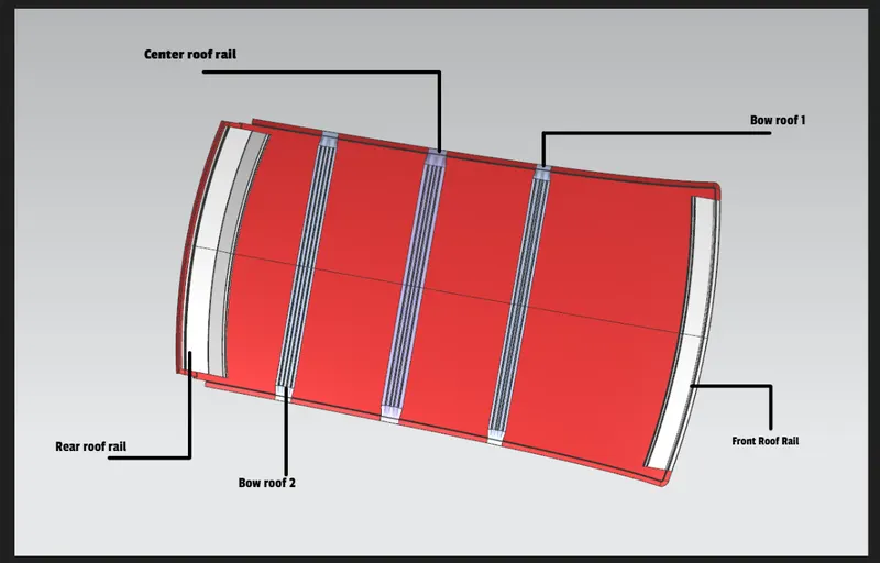
- It has parts like Outer panel, Front roof rail ,Rear roof rail , centre roof rail and bow roof rails for providing strength and mounting to other compartment.
- It is basically made of sheet metal.
Parts of Roof are
- Front Roof Rail
- Bow roof 1
- Center roof rail
- Bow roof 2
- Rear roof rail
DESIGN CONSIDERATION FOR ROOF
- Curvature Study (Heat Distortion and Snow Load Prediction)
- Visiblilty Criteria
- Head Clearance
Curvature Study -
- we will do heat distortion and snow load prediction for our roof.
- If the result does not pass we have to add emboss in that area , change the position of our bow roofs etc so that we can provide more strength.
- Detail about this will be explained later.
Visiblilty Criteria and headroom criteria
- Visibility as well as Head room clearance totally depend upon front roof rail.
- So the dimensions of front roof rail should such that it does not effect driver vision.
- Proper head room clearance should be there between head and the inner surface of front roof rail.
Desging Roof Components/Parts
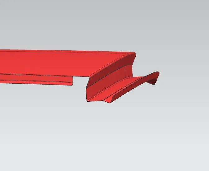
1.Outer Panel Of Roof
- The outer panel of roof give aesthetic look to our car.
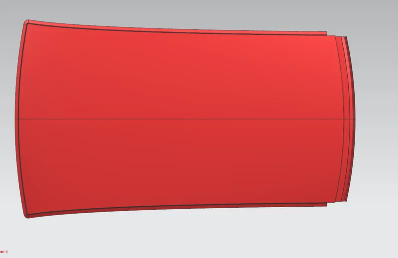
- So,here first we will extract the class A surface and trim it from middle.
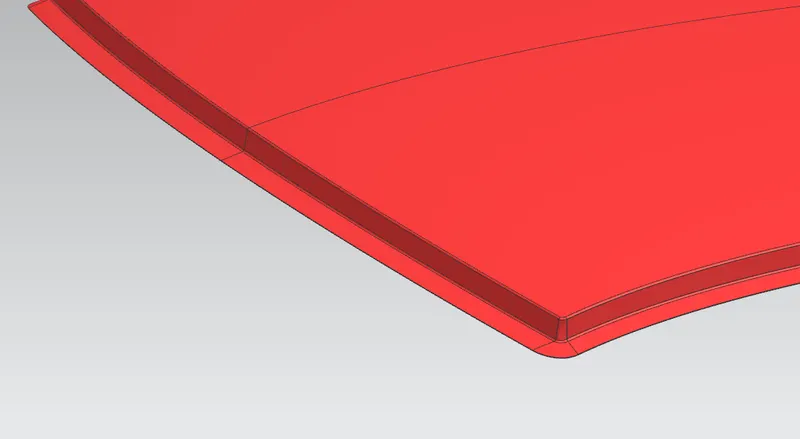
- Now our walk is to make ditch area.
- Ditch area is the extended part of our outer pane in the edges l which is used for joining other parts to roofs using spot welding.
- This area is design with the help of master section.
Front Roof Rail
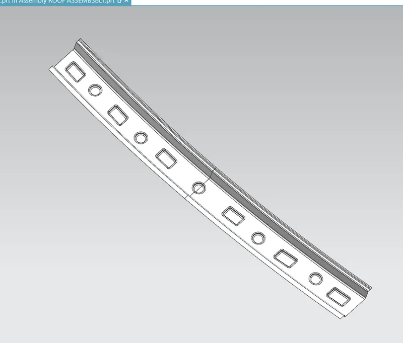
- As the name suggest this component is in the front of our roof.
- Its purpose is to attach the windshield and outer roof panel and A pillar.
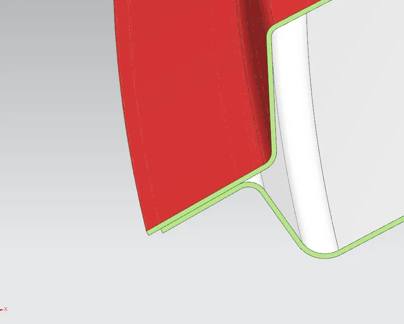
- In this Spot welding is used to join with ditch area outer roof panel .
- For developing front roof rail I have used demensions of the master section and at some part angle is given according to draft needs,so that it will easily manufacturable.
- Embosses are provided for adding strengthen to the part.
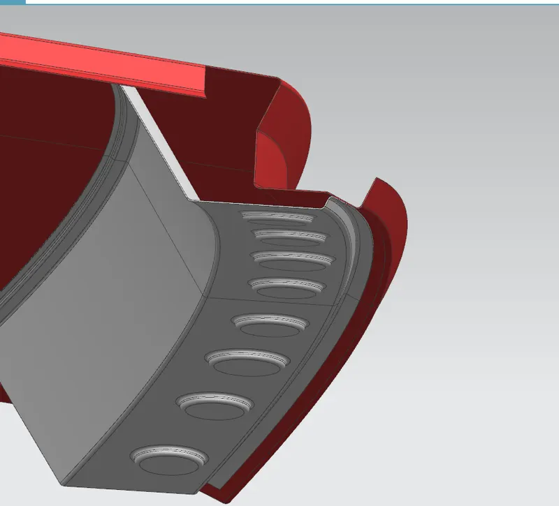
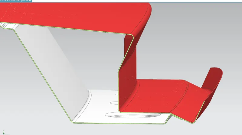
Rear Roof Rail
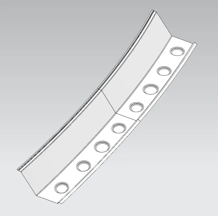
- The rear roof rail is located at the rear part of the roof
- Before designing the rear roof rails of we should keep rare headroom clearance and rear visible criteria.
- It join with the back door and body side outer part.
- Again this part is design with the dimensions given as in master section.
Bow Roof Rail
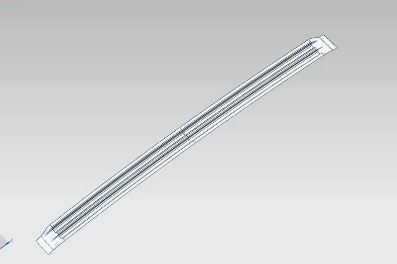
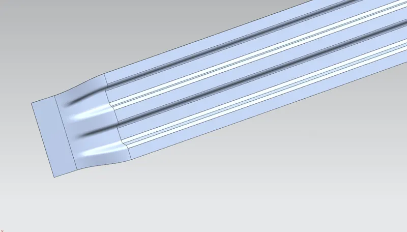
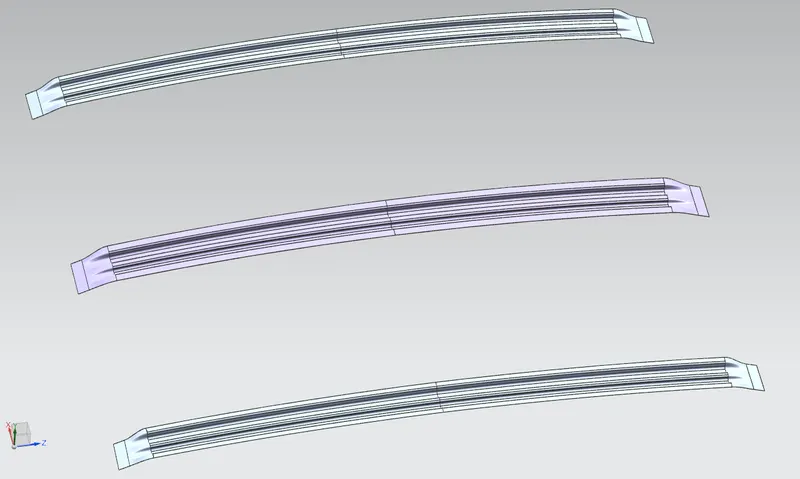
- The bow roof is the supporting part of roof which is added to provide strength to our roof.
- These are positioned especially where our surface is more flat.
- The number of bow roof rail depend on size and the curvature of our roof.
Centre Roof Rail
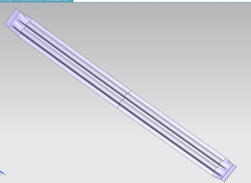
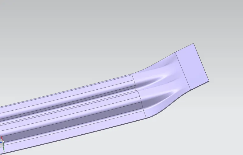
- Centre roof is similar to bow Roof but they are more wider than bow roofs.
- They are mostly place in the centre portion of the roof and which is connected to be B-pillar supports structure.
- I have taken dimensions for centre roof is according to master section.
CALCULATIONS
CURVATURE STUDY
In the curvature study we will do two study
- Heat distortion criteria
- Snow load prediction
Heat distortion criteria
- As we know , when the metal is exposed to temperature ,the metal start deforming so with the help of heat distortion study we can check the ability of roof to withstand high temperature.
- If our heat distortion criteria doesn't pass there are many ways add the strength.
- we can add emboss to our roof or we can add more bow roof rails or increase the thickness, cross section area of reniforcement.
- And also with this we can change position of the reinforcement if required, to increase the strength of roof.
Bow–Roof Prediction Formula
W = [1.73 x 10^(-3) x L] + [1.85 x 10^(-8) x (R^2)/t] + [ 1.10x10^(-3) x l] - 2.68
Where,
- L = Roof Length in X-Direction[mm](Roof dimension in 0-Y)
- R = Roof curvature
- R = 2(Rx*Ry)/(Rx+Ry)
- Rx = X curvature
- Ry = Y curvature
- t = Roof plate thickness [mm]
- l = Bow Roof Span [mm]
Procedure
- In the sketch first we have made a line which is at the centre and passing through X axis.
- Now we have offset this line 300 mm in downwards direction
- Now we have made upset of 100 mm in both directions
- Now with the help of points we have find centre of our parts (front roof rail , bow roof rail 1, centre roof rail, bow roof rail2 and rear roof rail)
- With this point we have got centre point of between two parts.
- At these points I have drawn a vertical lines
- now I have offset 100 mm in both the side of this lines
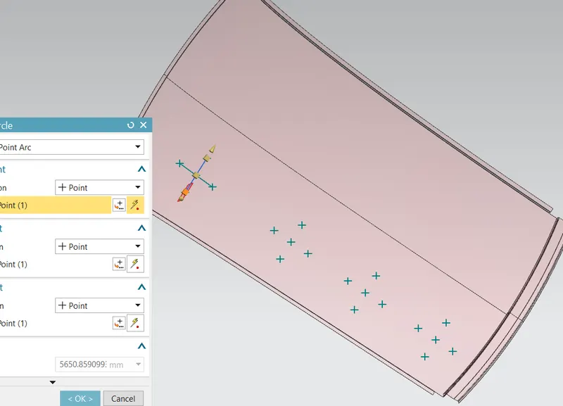
- And mark the intersection at 5 different point for each area as soon in below sketch.
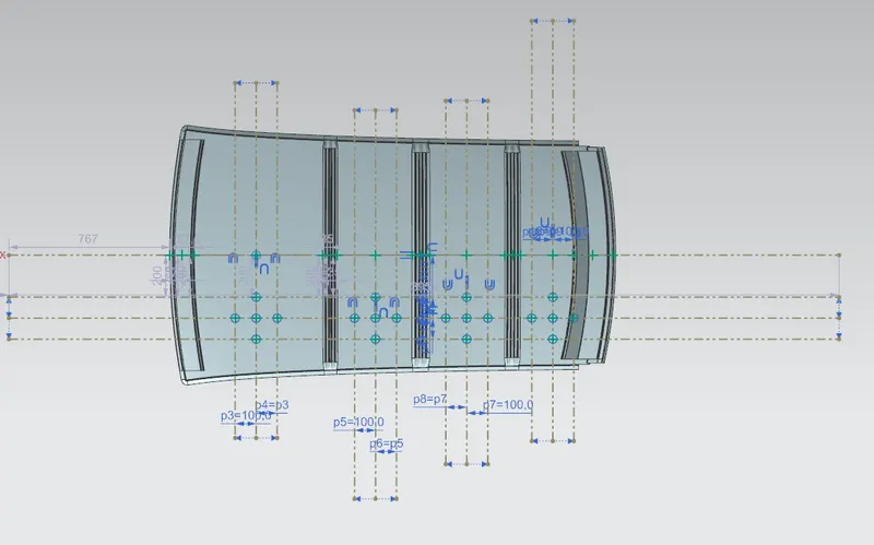
- Now I have projected this point in my surface and measured the Rx and Ry value with the help of three point arc.
Judgment Condition
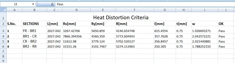
OK< 2.7
From the above table , the positioning of the bow roofs meets the condition for Heat Distortion Criteria.
Snow Load Prediction
- This type of study is done in countries where there is lot of snowfall.
- If the snow is collected over our roof, so the snow will act as a load and will try to bend the roof, we want our structure such that the roof should not change its shape after the removing that snow.
- It should come to its original position after removing that snow.
- We do this study between the 2 parts because they will deform easily as they do not have any support.
Snow Load Prediction Formula
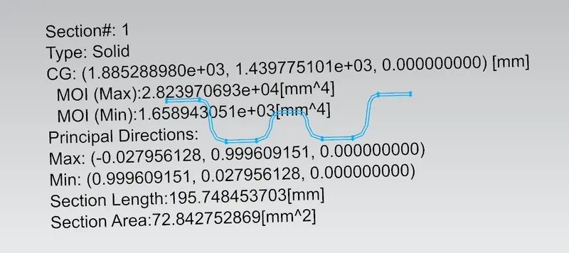
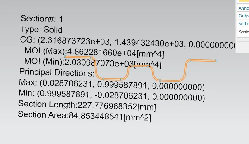
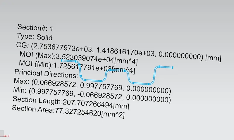
Qr = [Iy x t2] / [α x s x [(Rx + Ry)/2]2 x 10-8]
Where,
α = My x Lx2 x 10-12 , My = Y(Ly-Y)
t = Roof plate thickness [mm]
Ly = Distance between the front and rear roof Rails on the Vehicle along with 0Y[mm]
Length of Roof panel with the center point between Roof rail Front /Rear as the front and rear reference point.
Lx = Distance between the Left and Right end of the roof on the Roof BOW [mm]
The width of the roof panel is exposed on the surface.
Y = Distance front Front Roof Rail to Roof BOW[mm]
s = Distance for which Roof BOW bears divided load [mm]
s = L1/2 + L2/2
Iy = Geometrical moment of inertia of Roof BOW (Y cross-section )[mm4]
Rx = Lateral direction curvature radius of roof panel Y cross-section on Roof BOW [mm]
Roof panel curvature Radius of the Length Lx in Front view
Ry = Longitudinal Direction curvature radius of the Roof panel X cross-section on Roof BOW [mm]
Roof panel X curvature radius of length s in Side view
Procedure
For Rx and Ry
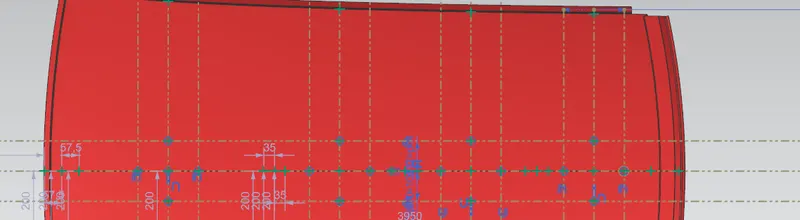
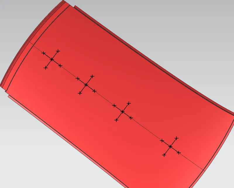
To find the Rx and Ry value the steps are almost same but in this we will not take 300mm offset.
we will take horizontal line and offset 100 mm both side of this line.
And other step are same, so after projection we will get our RX and Ry value.
Moment of Inertia for Bow Roof 1
Moment of Inertia for Center Roof Rail
Moment of Inertia for Bow Roof 2
Judgment condition
Qr ≥ 3.1

Since all are passinsg, so the positioning of the bow roofs satisfying the condition for snow load Criteria.
Draft analysis
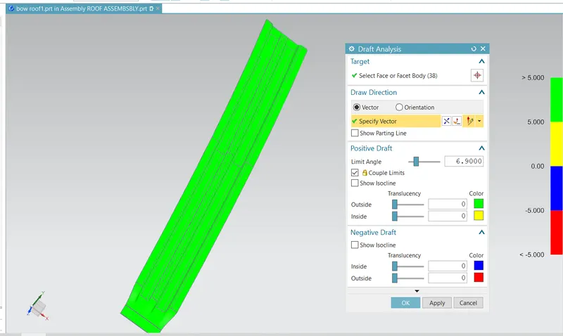
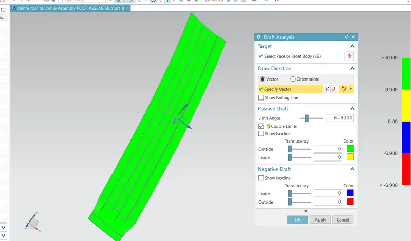
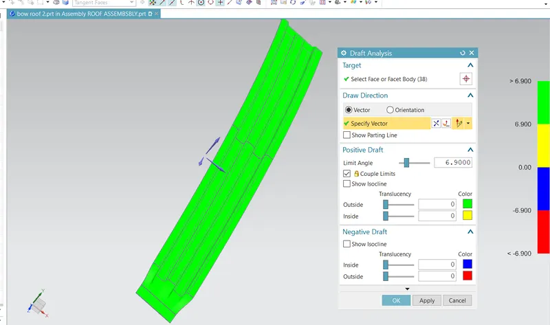
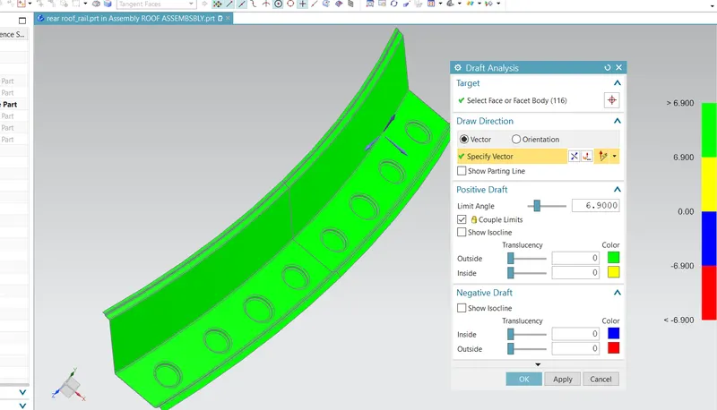
- For easy manufacturing of our component we provide at least 7 degree draft.
- Below are the images of all the part showing the result of drop analysis.
Draft Analysis for Front Roof Rail
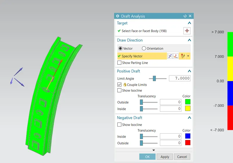
Draft Analysis for Bow Roof 1
Draft Analysis for Centre Roof Rail
Draft Analysis for Bow Roof 2
Draft Analysis for Rear Roof Rail
Draft Analysis for Outer Roof Panel
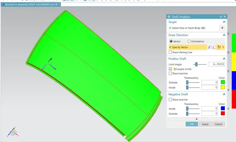
(Sum of my area will not clear for outer roof panel because we have taken - I've angle from master section)
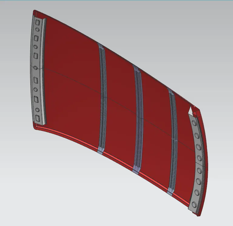
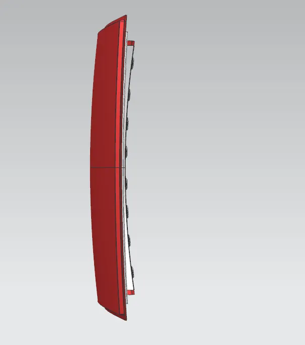
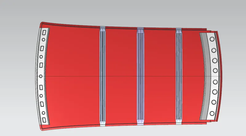
VIEWS
CONCLUSION
So I have design roof with all necessary reinforcements according to master section and and checked the curvature study and performed draft analysis.