Roof Design
ROOF DESIGN
INTRODUCTION:
What is “ROOF”?
An automobile roof or car top is the portion of an automobile that places above the passenger compartment, protecting the vehicle occupants from sun, wind, rain, and other external elements.
ROOF VARIANTS:
- Convertible roofs - A passenger car that can run with or without roof.
- Hard top – A rigid form of metal roof that can be either fixed, detachable storing with in the vehicle.
- Sun roofs – A sun roof that can be a movable roof portion on itself and it can be operate by manually or driven by motor. And it allows light and fresh air enters into the passenger compartment.
- T-tops – A roof with a removable panel on each side of a rigid bar running from the centre of one structural bar between pillars to the centre of the next structural bar.
- Targa tops – A semi-convertible car body style with the removable roof section and a full width roll bar behind the seats.
- Vinyl roofs – It refers as a vinyl covering of an Automobile roof.
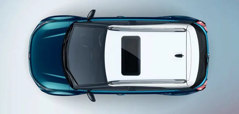
Fig_1: Roof_Top view of a car
MAJOR PARTS OF ROOF:
- Roof outer panel
- Front roof rail
- Rear roof rail
- Centre roof rail
- Bow roof rail
DESIGN CONSIDERATIONS OF ROOF:
In this automotive roof design study, we need to consider the following design requirements are,
- Visibility criteria
- Head room clearance
- Heat Distortions criteria
- Snowed criteria.
1_VISIBILITIY CRITERIA
The visibility of front and rear glass of a car must have at least of 70% percent. And the purpose of the law is to prevent accidents caused by low visibility on the road.
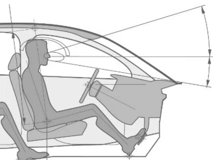
Fig_2: Roof _ Visibility criteria
2_HEAD ROOM CLEARENCE
Head room clearance is the one it can be defined as the distance between from the roof liner to the pedestrian’s head. And it is most important criteria for good seating comfort and relaxed driving of a car.
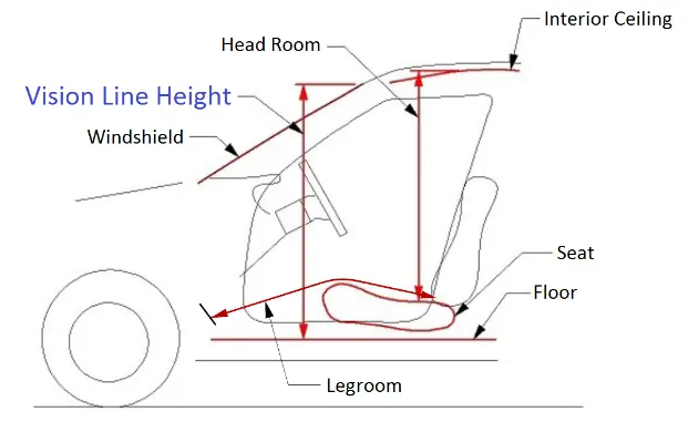
Fig_3: Roof _ Head room criteria
3_HEAT DISTORTION CRITERIA
This study can be used to predict the heat distortion temperature where the material starts to soften when exposed to a fixed load at elevated temperature. It can be calculated by using as below as,
Prediction Formula,
W = [ 1.73 x 10⁻³ x L] + [ 1.85 x 10⁻⁸ x (R2/t)] + [ 1.10x10⁻³ x l] - 2.68
Hence, the judgement condition of Heat Desertion Criteria is,
OK < 2.7 < NG.
L = Roof Length in X-Direction[mm] (Roof dimension in 0-Y)
R = Roof curvature
R = 2(Rx x Ry) / (Rx + Ry)
Rx = X curvature and Ry = Y curvature
t = Roof plate thickness [mm] and
l = Bow Roof Span [mm]
4_SNOWED CRITERIA
Prediction formula,
Qr = [Iy x t2] / [α x s x [(Rx + Ry)/2]2 x 10-8]
Judgement condition = Qr ≥ 3.1
250 ≤ s ≤ 380
Where,
α = My x Lx2 x 10-12, My = Y(Ly-Y)
t = Roof plate thickness [mm]
Ly = Distance between the front and rear roof Rails on the Vehicle along with 0Y[mm]
Length of Roof panel with the centre point between FR /RR as the reference point of front/rear.
Lx = Distance between the Left/Right end of the roof on the Roof BOW [mm]
Width of the roof panel exposed on the surface.
Y = Distance from Front Roof Rail to Roof BOW[mm]
s = Distance for which Roof BOW bears divided load [mm]
s = (L1/2) + (L2/2)
Iy = Geometrical moment of inertia of Roof BOW (Y cross-section) [mm4]
Rx = Lateral direction curvature radius of roof panel Y cross-section on Roof BOW [mm]
Roof panel curvature Radius of the Length Lx in Front view
Ry = Longitudinal Direction curvature radius of the Roof Panel X cross-section on Roof BOW [mm]
DESIGN OF AUTOMOTIVE ROOF:
OBJECTIVE:
To design an automotive roof and its components with respect to the all considerations and by using the given master section of components like FR roof rail, RR roof rail, Centre roof rail and bow roofs.
TOOL USED: NX_12
FRONT ROOL RAIL:
The front roof rail provides provision for the windshield glasses. Visibility criteria and headroom clearance have to be followed while designing the front roof rail. Provision for windshield mounting and inside rear view mirror is provided on the front roof rail. And it can be attached itself with roof outer panel by using mastic sealant and spot welding also etc., And its thickness 0.75 mm.
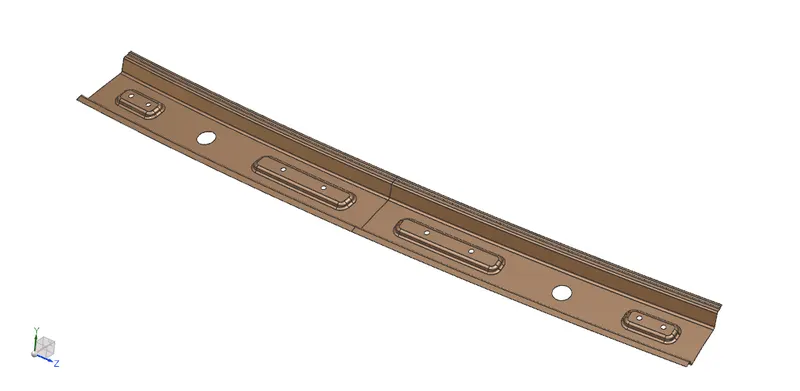
Fig_4: Roof _ Front roof rail
REAR ROOF RAIL:
The Rear roof rail has hinge mounting for the back door. It is attached at the portion where the back door meets with the roof. And it also considers head room clearance also. It can be attached by using mastic sealant and spot welding. Its thickness 0.75 mm.
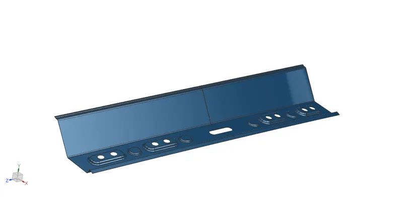
Fig_5: Roof _ Rear roof rail
CENTRE ROOF RAIL:
Reinforcement centre or centre roof rail is used as a cross member between Left hand and right-hand body sides. It has to be placed in the centre portions of the roof panel. And centre roof rail and reinforcement were joined by the help of using spot welding. And its thickness for roof rail 0.75 mm and the reinforcement thickness has to be maintained 0.75 mm to 1.5 mm.
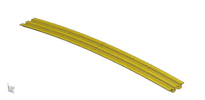
Fig_6: Roof _ Centre roof rail with reinforcement Centre
BOW ROOF RAIL:
Bow roofs are provided in between the front roof rail and centre roof rail as well as the Rear roof rail and centre roof rail. They are provided to enhance the localized strength of the roof and are attached directly to the bottom of the roof with either spot welding or with the help of Mastics. It should be placed in the flatter region of the roof panel and depending on the roof length its count may vary.
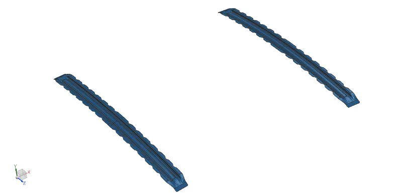
Fig_7: Roof _ Bow roof rail
DRAFT ANALYSIS OF ROOF RAILS:
1_FR ROOF RAIL:
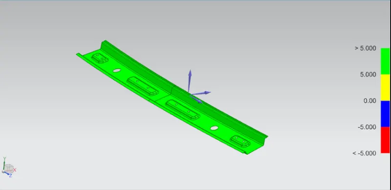
Fig_8: Draft Analysis _ Front roof rail
2_RR ROOF RAIL
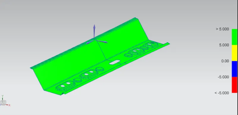
Fig_9: Draft Analysis _ Rear roof rail
3_CENTRE ROOF RAIL
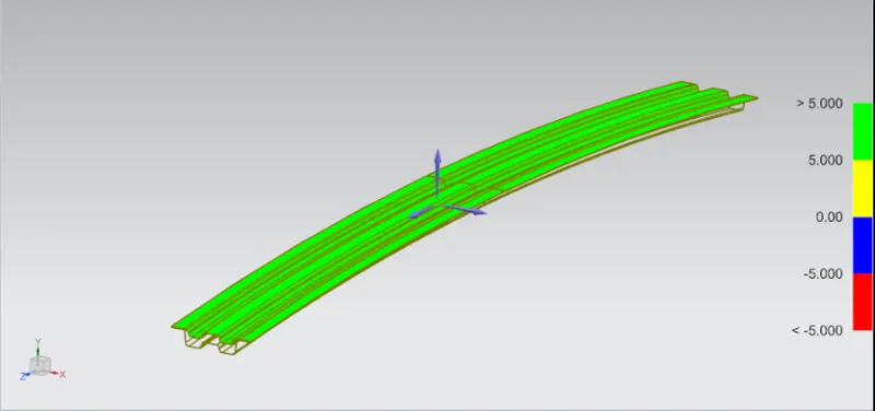
Fig_10: Draft Analysis _ Centre roof rail
4_BOW ROOF RAILS
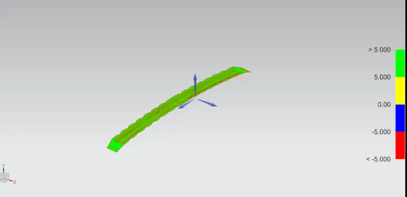
Fig_11: Draft Analysis _ Bow roof rail
SECTION INERTIA ANALYSIS:
By using this to calculate the min/max MOI of the roof rails are following are,
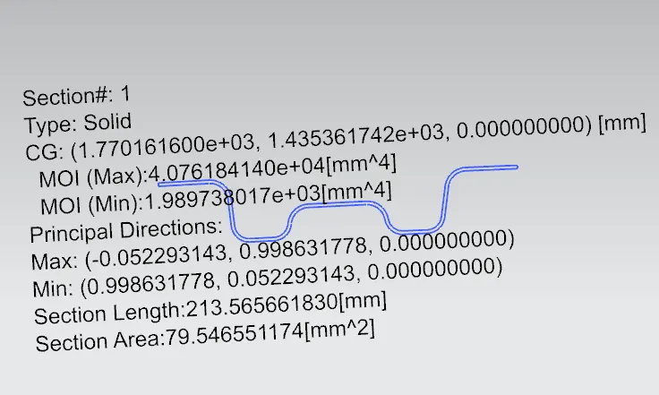
Fig_12: MOI of Bow roof rail 1
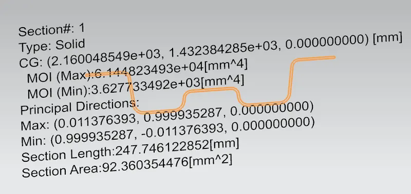
Fig_13: MOI of Centre roof rail
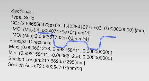
Fig_14: MOI of Bow roof rail 2
CALCULATIONS:
ROOF_HEAT DISTORTION CRITERIA CALCULATION:
W = [ 1.73 x 10⁻³ x L] + [ 1.85 x 10⁻⁸ x (R2/t)] + [ 1.10x10⁻³ x l] - 2.68
Judgement condition,
OK < 2.7 < NG.
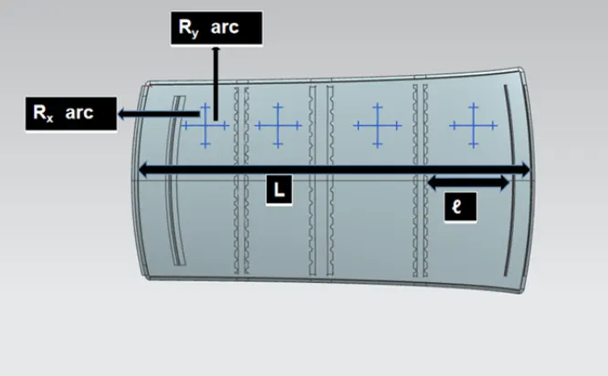
Fig_15: Heat Distortion_Annotations
|
S.No |
Bow’s |
RX |
RY |
R |
l |
L |
t |
R2/2 |
w |
OK/NG |
|
1 |
FR-1stBR |
5705.93 |
2817.51 |
3860.9 |
492.16 |
2033.7 |
0.75 |
19875369.96 |
1.79 |
OK |
|
2 |
1stBR-CR |
4845.75 |
6705.68 |
5626 |
305.04 |
2033.7 |
0.75 |
42202501.33 |
1.99 |
OK |
|
3 |
CR- 2ndBR |
3977.24 |
10582.33 |
5781.55 |
422 |
2033.7 |
0.75 |
44568427.2 |
2.17 |
OK |
|
4 |
2ndBR-RR |
3280.51 |
14586.1 |
5356.34 |
341.52 |
2033.7 |
0.75 |
38253837.6 |
1.96 |
OK |
Table_1: Roof Heat Distortion Criteria
ROOF_SNOWED CRITERIA CALCULATION:
Qr = [Iy x t2] / [α x s x [(Rx + Ry)/2]2 x 10-8]
Judgement condition = Qr ≥ 3.1
250 ≤ s ≤ 380
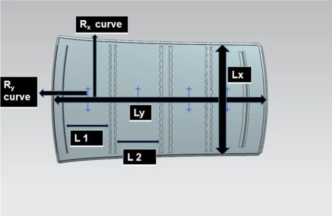
Fig_16: Snowed Criteria Annotations
|
S.No |
Bows |
IY |
α |
LX |
LY |
Y |
s |
RX |
RY |
t |
Qr |
OK/NG |
|
1 |
FR-1stBR |
1989.7 |
0.983 |
1138.5 |
2033.7 |
492.16 |
398.6 |
4314.33 |
2945.69 |
0.75 |
21.68 |
OK |
|
2 |
1stBR-CR |
3627.7 |
0.628 |
1091.2 |
2033.7 |
305.04 |
363.52 |
3797.46 |
6645.44 |
0.75 |
32.78 |
OK |
|
3 |
CR- 2ndBR |
2006.8 |
0.774 |
1066.8 |
2033.7 |
422 |
381.5 |
4275.80 |
11080.24 |
0.75 |
11.73 |
OK |
|
4 |
2ndBR-RR |
*** |
0.64 |
1052.3 |
2033.7 |
341.52 |
*** |
4006.93 |
16391.71 |
0.75 |
*** |
DIV/! |
Table_2: Roof Heat Distortion Criteria
ROOF ASSEMBLY DESIGN PIC'S REF:
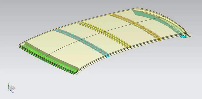
Fig_17: Roof Assembly
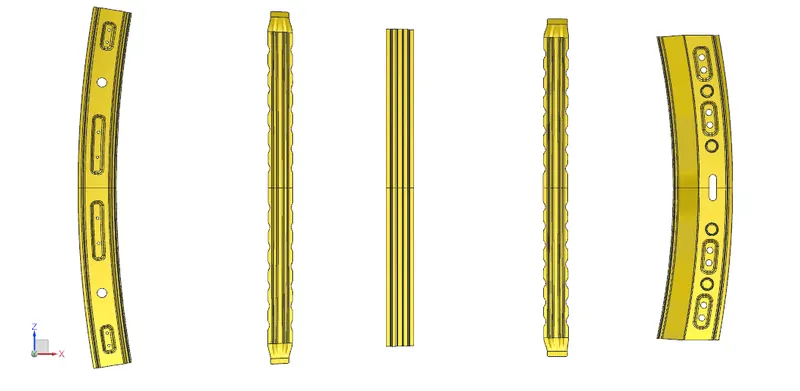
Fig_18: Roof rails
CONCLUSION:
Thus the automotive roof design assembly has been done by following all the design considerations of draft analysis, curvature study of roof panel Heat distortion and Snowed conditions calculations are tabulated and by using the given master sections for FR roof rail, RR roof rail, Centre roof rail and the Bow roof rail design are done by using NX_12.