Roof Design
AIM:
To design the roof of a car with reinforcements and to study on the Heat distortion and snow load criteria.
OBJECTIVES:
The objective of the project is to,
- For the given roof styling need to create an assembly by developing the essential flanges for the outer roof by creating the reinforcements as per master sections.
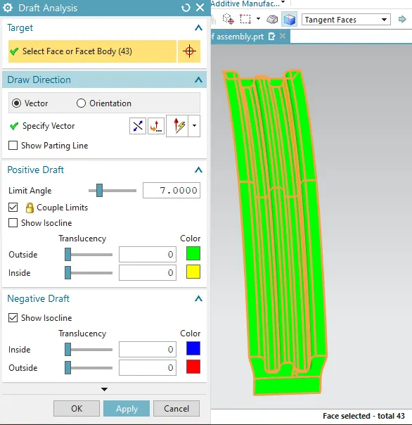
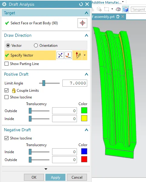
- Need to perform the draft analysis for each part in the assembly.
- Need to do the curvature study on the roof and perform the calculations for heat distortion and snow load criteria.
ROOF IN AUTOMOBILE:
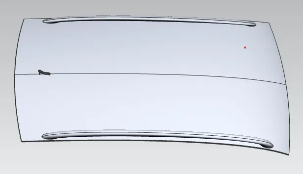
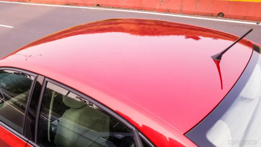
A roof is a car top portion above the passengers head to protect from sun,wind,rain and other external activites. Roofs are conventionally supported by pillars of the car body. Ditch area plays an important role here to fix the reinforcement on the component. The rails and reinforcements are joined to the ditch area with a spot weld where it's not the styling part.
VARIATIONS IN ROOF:
The variations developed in automabile car roof top are as follows
- covertible roofs
- Hard tops
- Sun roof tops
- T-tops
- Targa tops
- vinyl roofs
REINFORCEMENT TO ROOF:
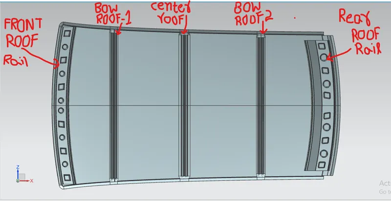
If the roof is plain it cannot withstand the load.To strenthening the roof we use some reinforcements to the roof. These reinforcements are joined to the roof surface using different joining process. The reinforcements generally used are as follows
- Front roof rail
- Bow roof rail
- center roof rail
- Rear roof rail
- Ditch area
FRONT ROOF RAIL:
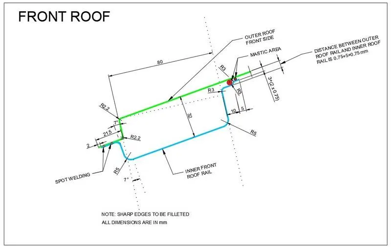
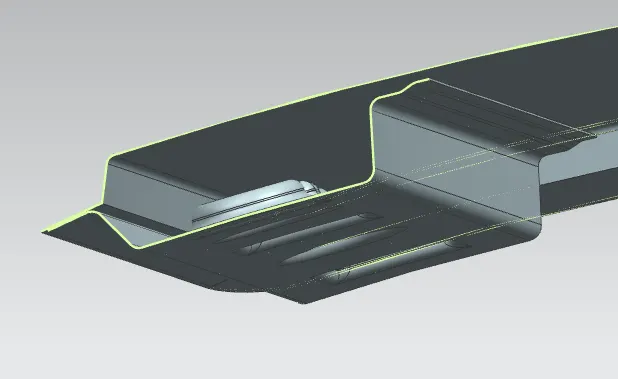
- Front roof rail was joined to the wind shield glass,body outer and inner panel.
- Front roof rail thickness was made 0.75mm as per master section
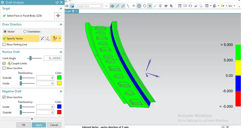
- Draft angle was provided in between 5-7 degrees for easy machinability of the component.
- The bottom flange is designed by maintaing the visibility criteria and head clearance.
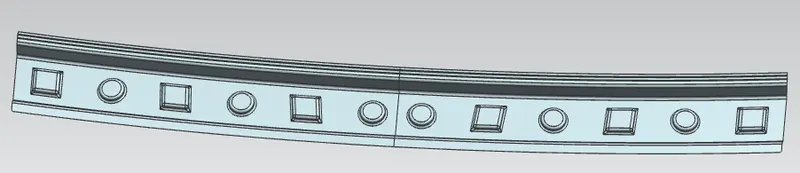
- Embosses was provided
- spot welding will be done at the wind shield side and mastek sealent will be applied at other end of the front roof rail.
- Draft analysis was done and cleared the draft analysis.
REAR ROOF RAIL:
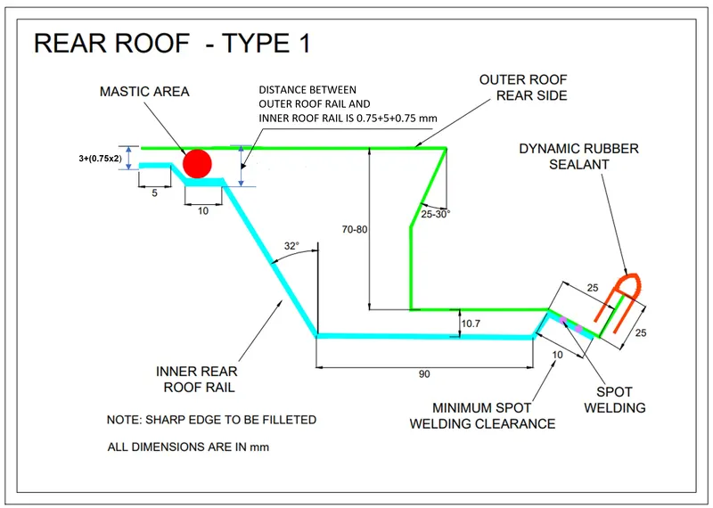
- Rear roof rail was supported and joined to the back door and body outer and inner panel.
- Rear roof rail thickness was made 0.75mm as per master section
- Draft angle was provided in between 5-7 degrees for easy machinability of the component.
- The bottom flange is designed by maintaing head clearance at the back door.
- Embosses was provided
- spot welding will be done at the back door end of the rail and mastek sealent will be applied at other end of the rear roof rail.
- Draft analysis was done and cleared the draft analysis.
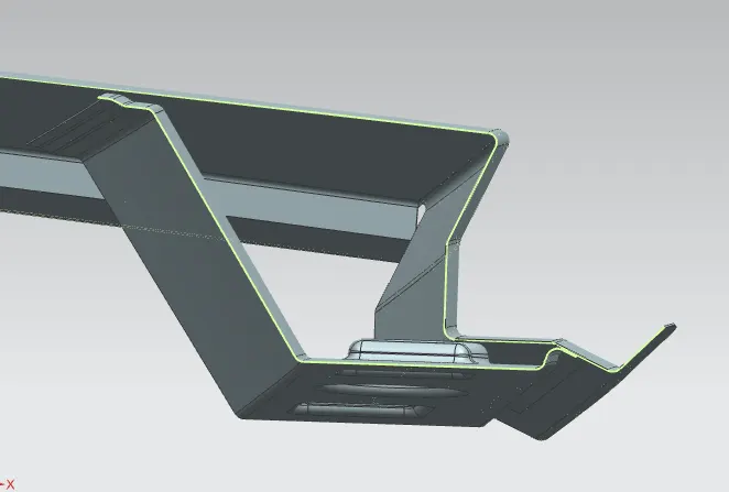
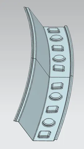
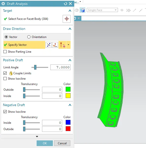
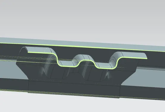
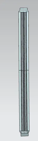
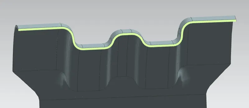
CENTER ROOF RAIL:
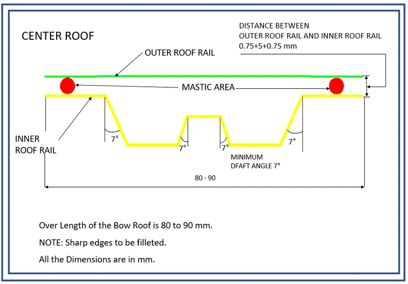
- center roof rail helps in supporting the flat area of the roof for with standing the load
- supported and joined to the pillars, body outer and inner panel.
- center roof rail thickness was made 0.75mm as per master section
- Draft angle was provided in between 5-7 degrees for easy machinability of the component.
- The center roof rail is designed by maintaing head clearance and visibilty criteria
- Embosses was provided
- spot welding will not be done instead mastek sealent will be applied due to asthetic surface.mastek sealent applies strength to the roof
- Draft analysis was done and cleared the draft analysis.
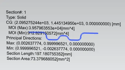
MOMENT OF INERTIA OF CENTER ROOF RAIL:
BOW ROOFS:
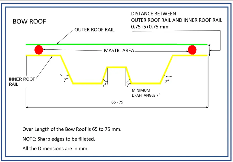
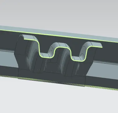
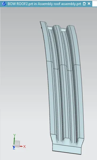
- The bow roofs are give to improve the torsional stiffness and load bearing capacity of the roof structure .
- The number of bow roof present is depends on the overall size of the roof .
- supported and joined to the pillars, body outer and inner panel.
- Bow roofs thickness was made 0.75mm as per master section
- Draft angle was provided in between 5-7 degrees for easy machinability of the component.
- Embosses was provided
- spot welding will be done at the ditcharea and mastek sealent will be applied due to asthetic surface.mastek sealent applies strength to the roof
- Draft analysis was done and cleared the draft analysis.
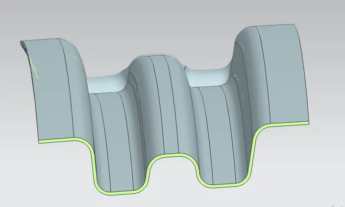
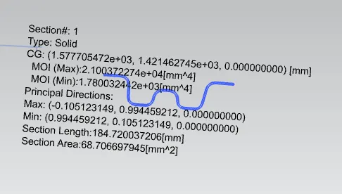
MMEMT OF INERTIA OF BOW ROOF1&2:
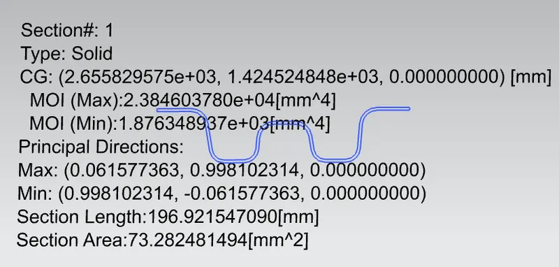
HEAT DISTORTION STUDY ON THE ROOF:
Heat distortion theory is the temperature at which the metal softens and deforms under a specific load. This study is done to check the ability of the roof to withstand high temperature with respect to the positioning of the reinforcements which contribute to increased strength.
Bow–Roof Prediction Formula
W = [1.73 x 10^(-3) x L] + [1.85 x 10^(-8) x (R^2)/t] + [ 1.10x10^(-3) x l] - 2.68
Where,
L = Roof Length in X-Direction[mm](Roof dimension in 0-Y)
R = Roof curvature
R = 2(Rx*Ry)/(Rx+Ry)
Rx = X curvature
Ry = Y curvature
t = Roof plate thickness [mm]
l = Bow Roof Span [mm]
Judgment Condition
OK< 2.7
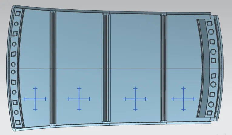
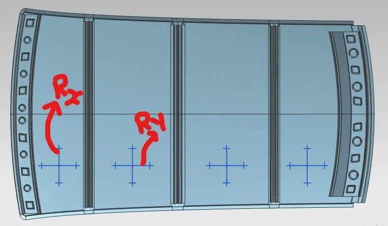
applying all the values obtained from the desig in the above formula
CALCULATION:
| HEAT DISTORTION CRITERIA CALCULATION | ||||||||||
| STAGES | RX | RY | RX+RY | RX*RY | R | L | t | l | w | RESULT |
| FR-BOW1 | 5740.2178 | 2356.619 | 8096.837 | 13527506.33 | 3341.4299 | 2025.6 | 0.75 | 297.7201 | 1.427187 | PASS |
| BOW1-CR | 5116.1659 | 5614.7539 | 10730.92 | 28726012.44 | 5353.877 | 2025.6 | 0.75 | 444.5712 | 2.020362 | PASS |
| CR-BOW2 | 4039.3883 | 10268.181 | 14307.57 | 41477169.39 | 5797.9338 | 2025.6 | 0.75 | 486.1425 | 2.18824 | PASS |
| BOW2-RF | 3320.2996 | 14325.438 | 17645.74 | 47564746.73 | 5391.0749 | 2025.6 | 0.75 | 338.7124 | 1.913776 | PASS |
From the above table it can be concluded that all values of w<2.7 so thus infers that current positioning of bow row are good in state as per design and found ok.
SNOW LOAD CRITERIA:
This test is done to know about how the roof behaves when snow was falls on the roof.Due to weight of the roof the dent will form on the roof and should regain its original position.For this requirement snow load criteria should pass.
Snow Load Prediction Formula
Qr = [Iy x t2] / [α x s x [(Rx + Ry)/2]2 x 10-8]
Note: The Qr value given over here is correct. There was a typo error in the formula given in the video.
Where,
α = My x Lx2 x 10-12 , My = Y(Ly-Y)
t = Roof plate thickness [mm]
Ly = Distance between the front and rear roof Rails on the Vehicle along with 0Y[mm]
Length of Roof panel with the center point between Roof rail Front /Rear as the front and rear reference point.
Lx = Distance between the Left and Right end of the roof on the Roof BOW [mm]
The width of the roof panel is exposed on the surface.
Y = Distance front Front Roof Rail to Roof BOW[mm]
s = Distance for which Roof BOW bears divided load [mm]
s = L1/2 + L2/2
Iy = Geometrical moment of inertia of Roof BOW (Y cross-section )[mm4]
Rx = Lateral direction curvature radius of roof panel Y cross-section on Roof BOW [mm]
Roof panel curvature Radius of the Length Lx in Front view
Ry = Longitudinal Direction curvature radius of the Roof panel X cross-section on Roof BOW [mm]
Roof panel X curvature radius of length s in Side view
Judgment condition
Qr ≥ 3.1
250 ≤ s ≤ 380
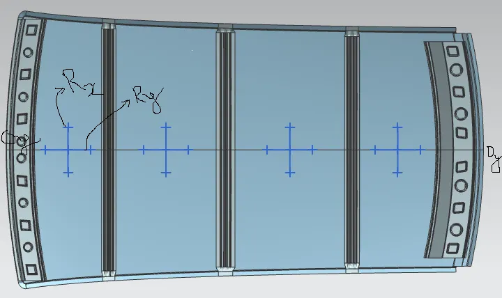
applying all the values obtained from the desig in the above formula
CALCULATION:
| SNOW LOAD CRITERIA | |||||||||||||||
| STAGES | Iy | Lx | Ly | Rx | Ry | (Rx+Ry/2)^2 | L1 | L2 | Y | t | S | My | Alfha | Q | Result |
| FR-BOW1 | 1780.03 | 1115.091 | 1930.32 | 4689.758 | 2386.49 | 12518322.5 | 390.8814 | 517.7399 | 390.881 | 0.75 | 454.3107 | 601737.5 | 0.748218 | 23.53005 | PASS |
| BOW1-CR | 912.8291 | 1071.583 | 1930.32 | 3754.09 | 5513.489 | 21472006.1 | 517.7399 | 560.6381 | 908.621 | 0.75 | 539.189 | 928337.2 | 1.065999 | 4.16046 | PASS |
| CR-BOW2 | 1876 | 1047.564 | 1930.32 | 4245.11 | 10699.04 | 55831870.4 | 560.6381 | 461.0607 | 1469.259 | 0.75 | 510.8494 | 677418 | 0.743391 | 4.976944 | PASS |
From the above table it can be concluded that all values of Qr ≥ 3.1 so thus infers that current positioning of bow row are good in state as per design and found ok.
SECTION MODULUS:
For rear roof rail:
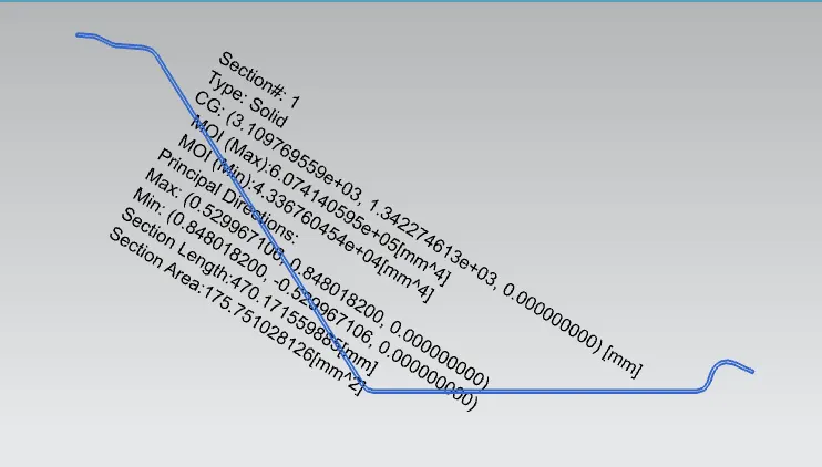
For Front roof rail:
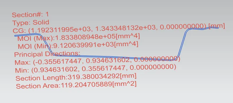
For center roof rail:
For bow roof-1:
For bow roof-2:
Tabular form:
| SECTION MODULUS | |||||
| SLNO | SECTIONS | Y | Ymax | I | S |
| 1 | FRONT ROOF RAIL | 123.378 | 61.689 | 9120 | 147.8384 |
| 2 | REAR ROOF RAIL | 222.512 | 111.256 | 43360 | 389.7318 |
| 3 | CENTER ROOF RAIL | 83.32 | 41.66 | 912.129 | 21.8946 |
| 4 | BOW ROOF 1 | 63.31 | 31.655 | 1780 | 56.23124 |
| 5 | BOW ROOF 2 | 65.786 | 32.893 | 1876 | 57.03341 |
RESULT:
As per the heat distortion criteria, positions of all the bow roof and reinforcement centre are under acceptable conditions.
CONCLUSION:
Finally we conclude roof , front roof rail, bow roof rails , central roof rail and the rear roof rail is designed by using the master sections and the moment of inertia , section modulus and draft analysis are carried out to check feasibility manufacturing.