Roof Design
ROOF DESIGN
Aim
To design and develop the roof from the given class A surface with front roof rail, bow roof rail, centre roof rail, rear roof rail and roof ditch area by considering all design parameters and check for draft angle, curvature analysis by calculating heat distortion, snow load criteria for the roof.
Introduction
An automobile roof is the portion of an automobile that sits above the passenger compartment, protecting the vehicle occupants from sun, wind, rain, and other external elements. Only the aesthetic surface is visible from outside and inside this there are many features like, roof rails, emboss which will strengthen the roof and protect it from external hazards.
Roof rails are joined to the aesthetic surface by means of mastics and spot welding techniques. If the roof having a good curvature and vehicle length is comparatively less than the nominal length then the bow roof rail is not required but it will be still considered if it is going for roof crush test like roll over test, IDHS, etc. Roof rails should be required for maintaining the heat distortion criteria and Snow Load Prediction criteria in the particular location.
Front roof rail
Front roof rail will be joint with the windshield glass, A pillar mount, the body side outer, inner panels and it supports Bracket lamp and room lamp. While designing the roof rails we should consider the roof head room clearance and the visibility criteria line.
Rear roof rail
Joint with back door and body side outer. While designing the roof rails we should consider the roof head room clearance, rear visibility criteria line and back door mounting.
Centre roof rail
Which connects the roof to the driver partition compartment area (front door side) by spot welding in the ditch area.
Bow roof rail
Bow roof rail will provide additional strength to the roof and the no of bow roof rails and it will be positioned by considering the heat distortion criteria, snow load prediction and length of the entire roof assembly. ditch area for spot welding is also required for joining it with the adjacent member.
Manufacturing process
Deep drawing
Deep drawing is one of the most widely used processes in sheet metal forming. Apart from its use in many other sectors, it is applied in the automotive industry for the manufacturing of car body parts.
The deep drawing process is a forming process which occurs under a combination of tensile and compressive conditions. A flat sheet metal blank is formed into a hollow body open on one side or a hollow body is formed into a hollow body with a smaller cross-section.
In the automotive industry, deep drawing is usually carried out using rigid tools. The rigid tools consist of a punch, die and binder. In deep drawing, the plate holder closes after the metal sheet blank has been inserted
Next the sheet is clamped between the die and the binder. This process slows down the flow of the sheet while it is being drawn and thereby prevents wrinkles from forming under the binder. The punch stretches the sheet over the die radius and forms it in the die. The amount of punch force necessary for forming is thereby continually increased up to the lower dead center of the punch.
Whereas in pure deep drawing there is no reduction of sheet metal thickness, forming is achieved in stretch forming purely as a result of a decrease in sheet metal thickness. Stretch forming is extensively used for the forming of only slightly curved parts with low depth of draw (e.g. roofs, doors).
When drawing complex car body parts in practice, there is usually a combination of stretch and deep drawing involved. It is necessary that the sheet metal is stretched as well as possible without reaching the material’s limits.
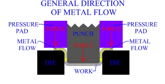
Deep drawing process
Draft analysis
The direction in which the Punch open and closes is the tooling axis. The die cavity matches the punch and is a little wider to allow for its passage, as well as clearance. Draft allows for the component to release from the die.
Input received
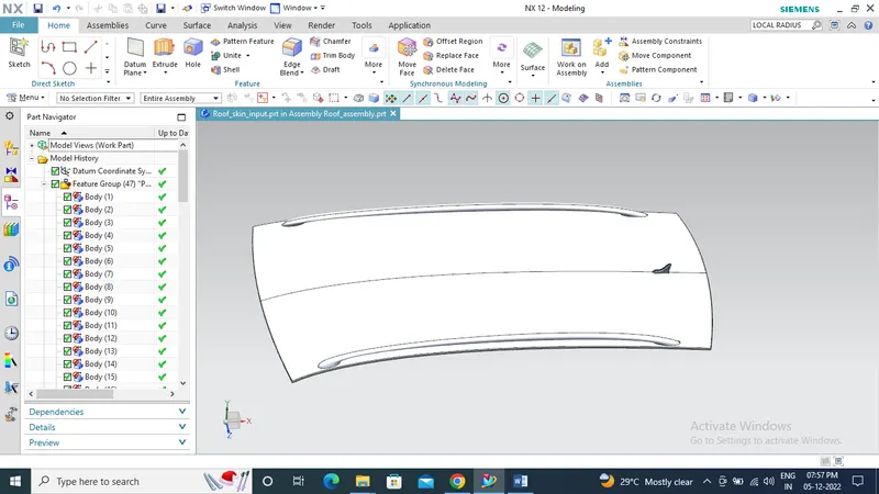
Class A surface
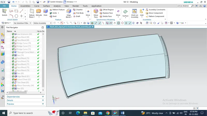
Modified class A surface with flanges
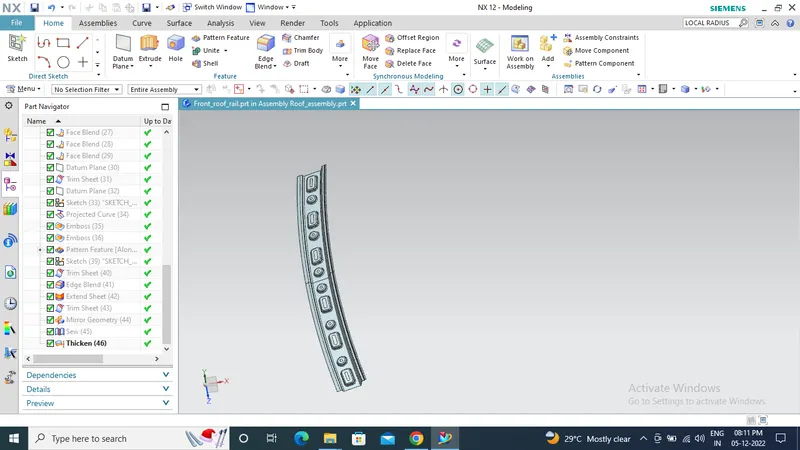
Front roof rail with emboss
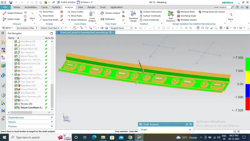
Draft analysis on front roof rail
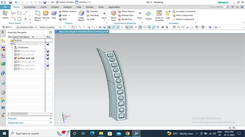
Rear roof rail with emboss
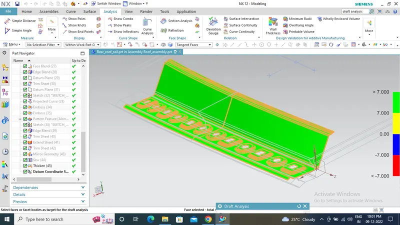
Draft analysis on Rear roof rail
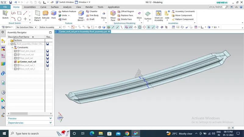
center roof rail
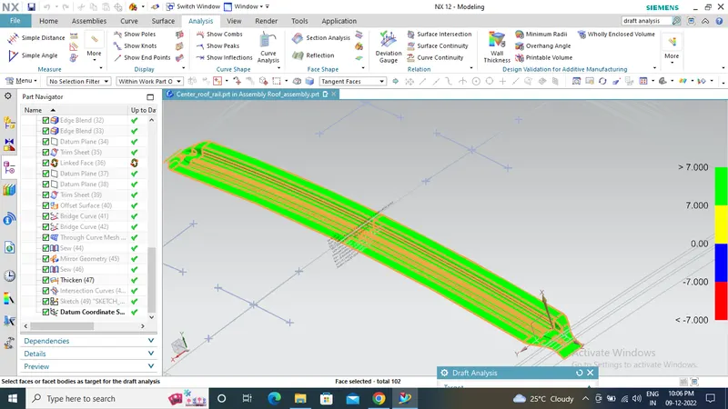
Draft analysis on center roof rail
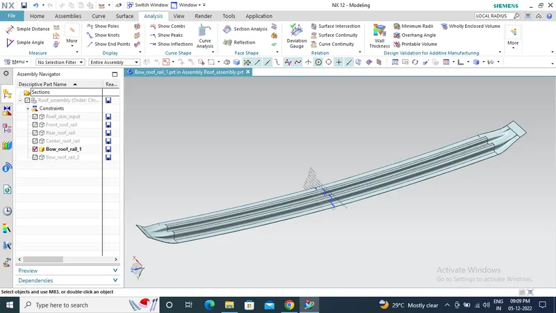
Bow roof rail-1
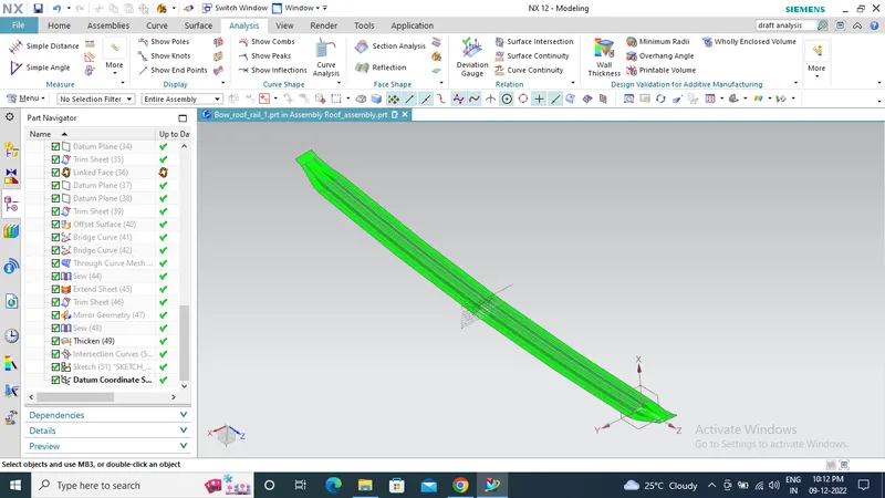
Draft analysis on Bow roof rail-1
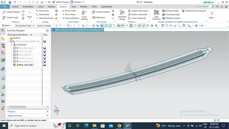
Bow roof rail-2
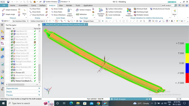
Draft analysis on Bow roof rail-2
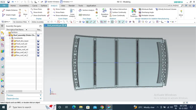
Roof with front, rear, center and bow roof rails
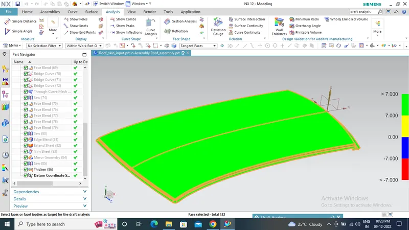
Draft analysis on roof
Heat distortion calculation
The heat distortion temperature (HDT) - also known as the deflection temperature under load (DTUL) or heat deflection temperature - is an important material property. It gives an indication at what temperature materials start to deform when exposed to a fixed load at elevated temperatures.
The formula used to calculate heat distortion of roof
W = [1.73 x 10^(-3) x L] + [1.85 x 10^(-8) x (R^2)/t] + [ 1.10x10^(-3) x l] - 2.68
Where,
L = Roof Length in X-Direction[mm](Roof dimension in 0-Y) (only for given class A surface)
R = Roof curvature,
R = 2(Rx*Ry)/(Rx+Ry)
Rx = X curvature
Ry = Y curvature
t = Roof plate thickness [mm]
l = Bow Roof Span [mm] (edge to edge)
The W value should be < 2.7 then it will pass the heat distortion criteria
Observations from the designed roof model
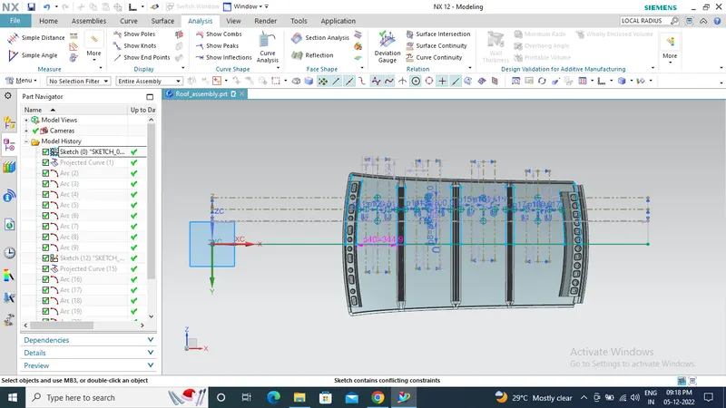
-3Y section from this 100mm on both sides and intersection point is the measuring point
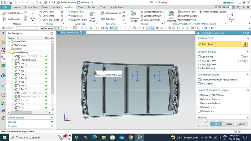
Curvature analysis in vertical direction (Rx value)
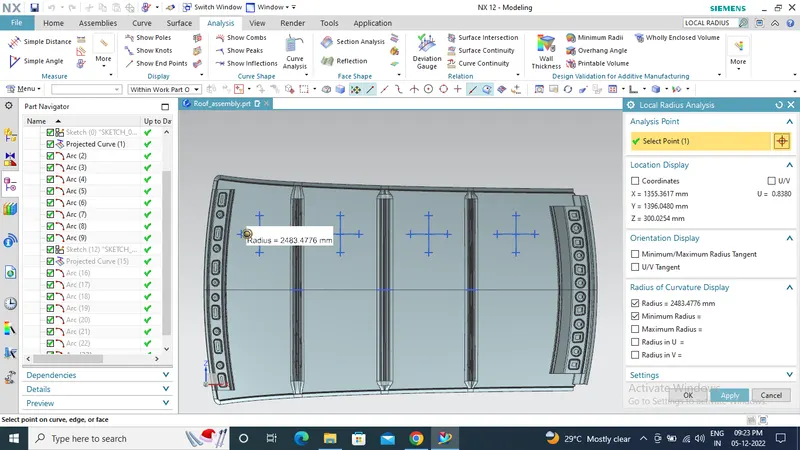
Curvature analysis in Horizontal direction (Ry value)
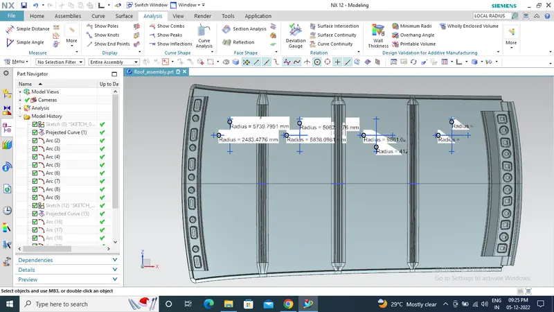
Curvature analysis of each section
Heat distortion calculation for the roof
|
Sl.No |
L |
Rx |
Ry |
R |
t |
l |
W |
Result |
|
1 |
2025.3 |
5739.799 |
2483.477 |
3466.905 |
0.75 |
344.89 |
1.499627 |
Pass |
|
2 |
2025.3 |
5062.706 |
5838.09 |
5422.821 |
0.75 |
391.51 |
1.979802 |
Pass |
|
3 |
2025.3 |
4120.66 |
9861.027 |
5812.452 |
0.75 |
385.579 |
2.081259 |
Pass |
|
4 |
2025.3 |
3380.968 |
13514.71 |
5408.815 |
0.75 |
386.75 |
1.970824 |
Pass |
From the above table we can conclude that the designed roof will pass the heat distortion criteria and having a good curvature.
Snow load prediction calculation
The magnitudes of loads imposed by snow depend upon a number of climatological and meteorological variables and as a result exhibit marked variations geographically, due to local effects within a particular region, and with time. The snow load formation process, which depends both on the macro- and microclimates of such meteorological variables as the depth of the snowfall, the snowfall density, wind speed, air temperature etc., as well as, the size and geometry of particular roofs and the influence of their immediate environment. This study is carried out to understand how the deformation of a material when exposed to a variable snow load conditions.
Snow Load Prediction Formula
Qr = [Iy x t2] / [α x s x [(Rx + Ry)/2]2 x 10-8]
Where,
α = My x Lx2 x 10-12
My = Y(Ly-Y)
t = Roof plate thickness [mm]
Ly = Distance between the front and rear roof Rails on the Vehicle along with 0Y[mm]
Length of Roof panel with the center point between Roof rail Front /Rear as the front and rear reference point.
Lx = Distance between the Left and Right end of the roof on the Roof BOW [mm]
The width of the roof panel is exposed on the surface.
Y = Distance front Roof Rail to Roof Bow [mm] (center to center)
s = Distance for which Roof bow bears divided load [mm]
s = L1/2 + L2/2
L1= Centre to centre distance between the adjacent roof rails along 0Y line. (for first section- front roof rail to the bow roof rail-1)
L2-Centre to centre distance between the adjacent roof rails along 0Y line (Bow roof rail-1 to centre roof rail).
Iy = Geometrical moment of inertia of Roof bow (Y cross-section ) [mm4]
Rx = Lateral direction curvature radius of roof panel Y cross-section on Roof bow [mm]
Roof panel curvature Radius of the Length Lx in Front view
Ry = Longitudinal Direction curvature radius of the Roof panel X cross-section on Roof bow [mm]
Roof panel X curvature radius of length s in Side view
The Qr value should be Qr ≥ 3.1 then it will pass the snow load criteria
Observations from the designed roof model
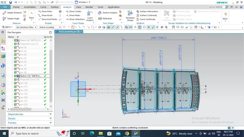
OY condition will be considered 100mm on both sides
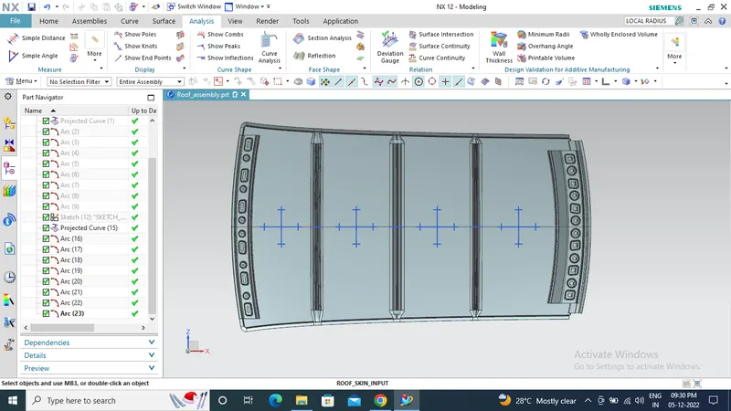
Curvature analysis
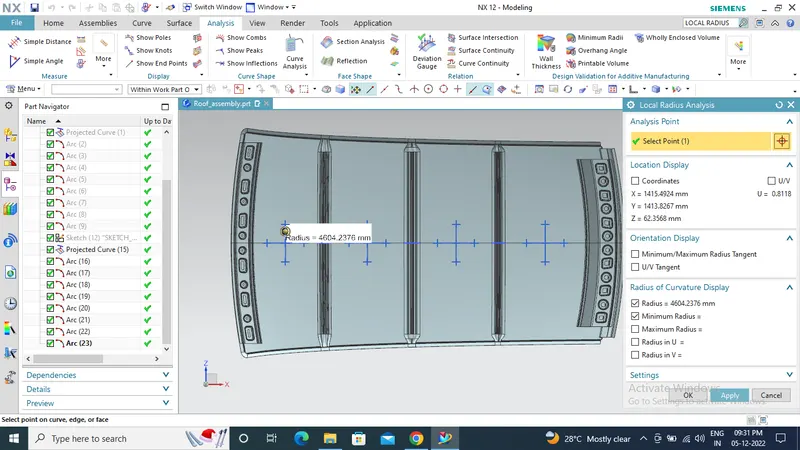
Curvature analysis in vertical direction (Rx value)
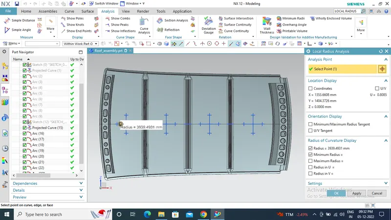
Curvature analysis in Horizontal direction (Ry value)
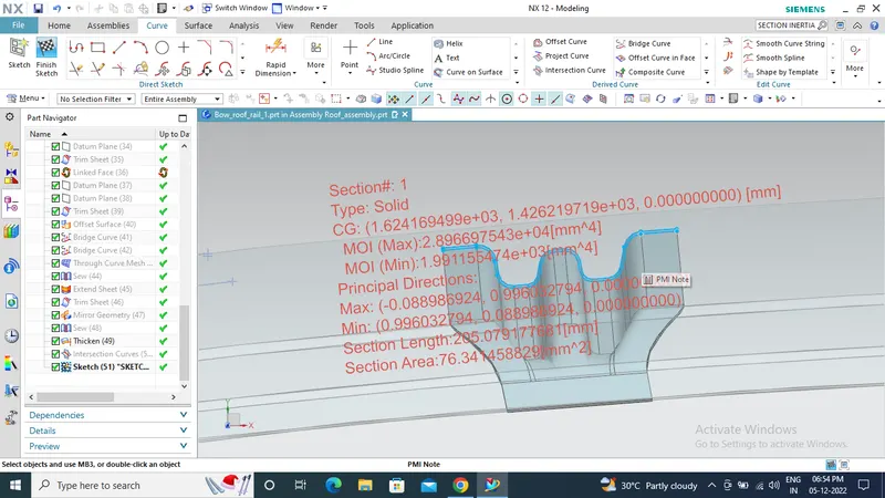
Moment of inertia at Bow roof rail-1
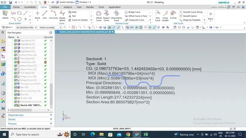
Moment of inertia at centre roof rail
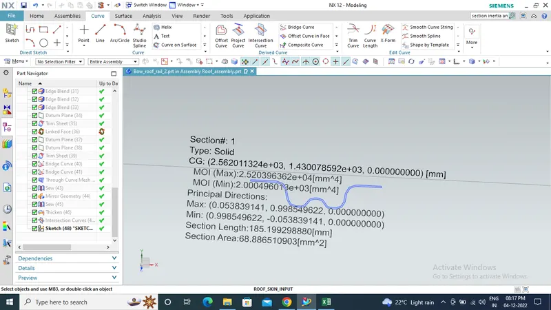
Moment of inertia at Bow roof rail-1
Snow load prediction calculation for the roof
|
Sl.no |
ly |
t |
Ly |
y |
My |
Lx |
α |
L1 |
L2 |
S |
Rx |
Ry |
Qr |
Result |
|
1 |
1,991.16 |
0.75 |
1936.3 |
443.8 |
662371.5 |
1109.2 |
0.814932 |
394.5 |
471 |
432.75 |
4604.23 |
3939.49 |
17.40 |
Pass |
|
2 |
2,508.92 |
0.75 |
1936.3 |
911.1 |
934059.7 |
1071.4 |
1.072205 |
471 |
464 |
467.5 |
3753.66 |
10022.31 |
5.93 |
Pass |
|
3 |
2,000.50 |
0.75 |
1936.3 |
1377.9 |
769419.4 |
1050.4 |
0.848931 |
464 |
545.4 |
504.7 |
3193.68 |
10211.52 |
5.85 |
pass |
From the above table we can conclude that the designed roof having a good curvature and will pass the snow load criteria. But the value of S is greater than 380mm which can be reduced by decreasing the distance between the roof rails by adding an additional bow roof rail or by adding embosses to the outer surface.
Conclusion
Thus we have design and developed a good curvature roof which follows all the design guidelines, maintained clear positive draft for manufacturing and passes the heat distortion criteria and snow load criteria.