Roof Design
Roof:
An automobile roof is the portion of an automobile that sits above the passenger compartment, protecting the vehicle occupants from sun, wind, rain, and other external elements.
Types:
- Convertible roofs
- Hardtops.
- Sunroofs.
- T-tops.
- Targa tops.
- Vinyl roofs.
Parts of the roof assembly:
- Front roof rail
- Rear roof rail
- Bow roof
- Center roof rail.
The above parts of the roof assembly is designed from the provided A surface of the roof and also the master sections.
1. Front roof rail:
As the name indicates, the front roof rail is assembled at the front of the roof. The front roof rail is designed considering it is assembled near the windshield area and the A-Pillar. Hence, visibility criteria and head clearance is an important criteria to be considered.
Front roof rail is designed based on the master section provided as below:
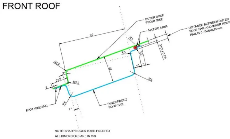
The front edge of the front roof rail is assembled with the roof by means of spot welding. Hence the gap/clearance between the roof and front roof rail at the front is zero. While at the rear edge of the front roof rail the gap/clearance between the roof and front roof rail is 5mm to accomodate the mastics.
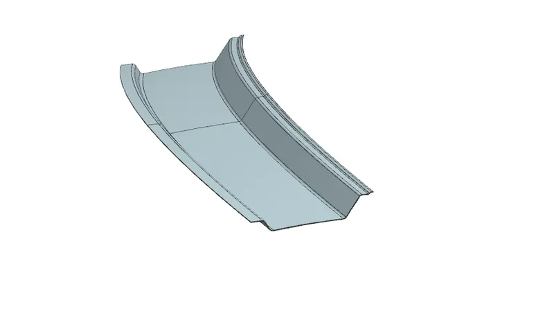
The part should be designed with proper draft angles, minimum of 7 degrees for easy ejection from the tool.
Draft analysis can be made using Siemens NX. Draft analysis for front roof rail is attached below.
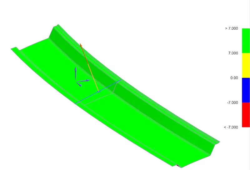
The above image shows that the part has sufficient draft angle.
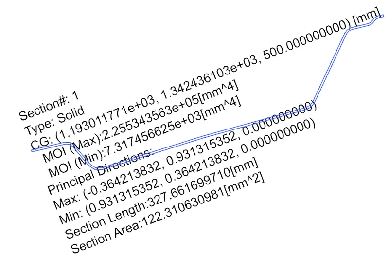
After checking the section inertia if its low, the part can be strengthened by providing emboss in the part.
2. Rear roof rail:
As the name indicates, rear roof rail is assembled at the rear side of the roof. The rear roof is assembled with the back door and body side outer.
The rear roof rail is designed as per the master section provided below:
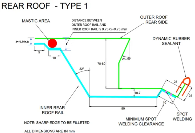
Similar to the front roof rail, one edge is spot welded with the roof and the other side is assembled with the help of mastics. The gap/clearance between the rear roof rail and roof is zero for spot weld region and 5mm for mastic region.
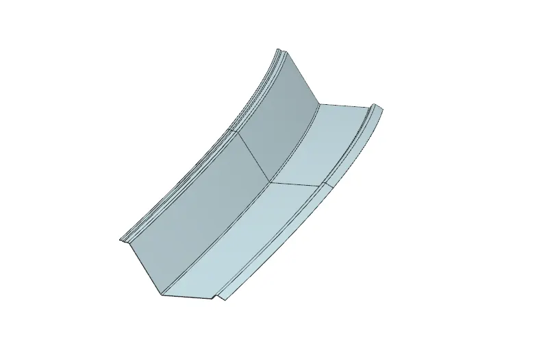
The draft analysis for the part is attached below.
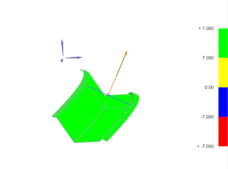
The part is provided with sufficient draft angle of minimum 7 degrees, which is evident from the above image.
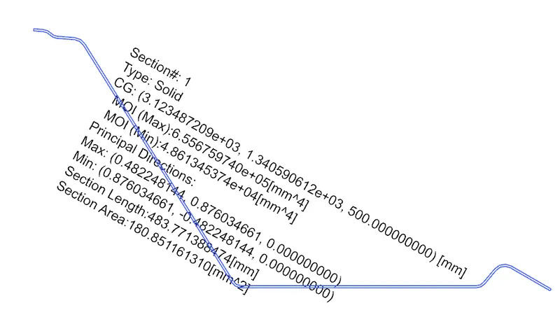
If more strength is required for the part, embosses can be provided to the part.
Bow Roof:
Bow roof is a part of the roof assembly, whose main objective is to strengthen the flat regions of the roof. Bow roofs are provided where there is a flat region in the roof, since flat regions are susceptible to get damaged soon. The can be two or more bow roofs based on the length of the roof.
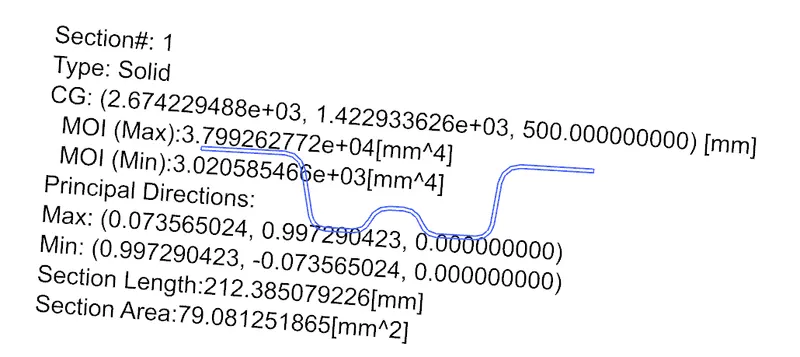
I have provided two bow roofs for the assembly of this roof. The bow roofs are designed based on the master section provided as below,
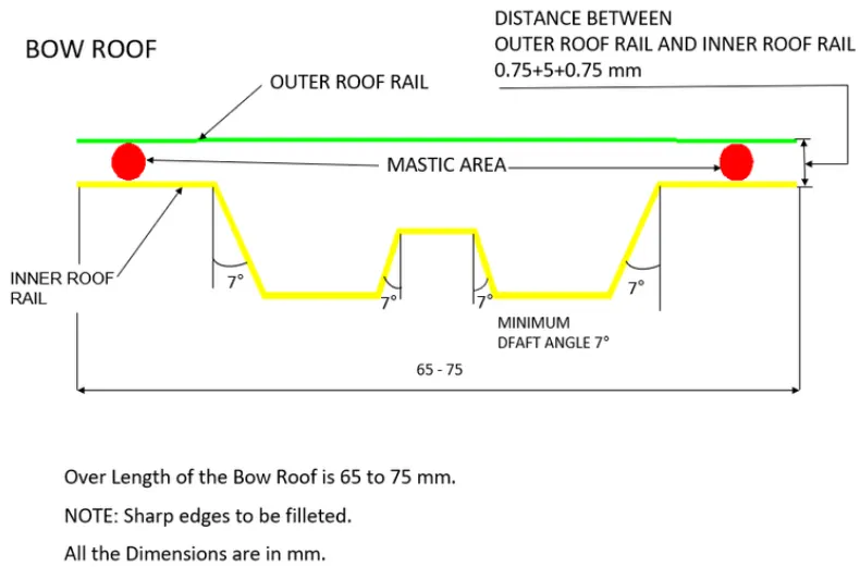
The bow roof is assembled with the roof on the outermost edges by means of spot welding and mastics in the center region.
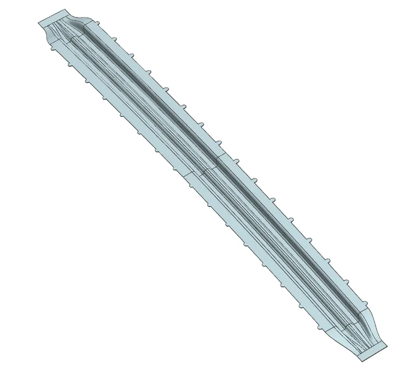
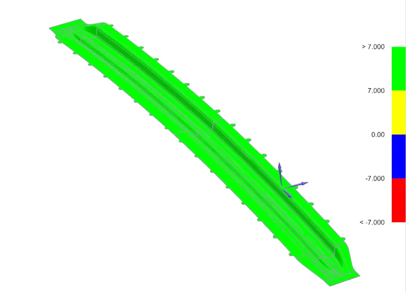
Both the bow roof are provided with sufficient draft angles.
Bow Roof 1
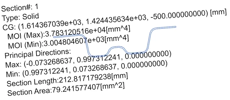
Bow Roof 2
Center roof rail:
Center roof rail is assembled in the center of the roof assembly. The center roof rail can be provided with a reinforcement if the sun roof is present. Center roof is designed based on the master section provided below
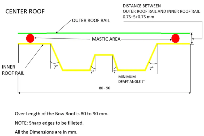
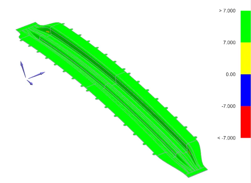
Draft analysis for the part is attached below, and the part is provided with proper minimum draft angles.
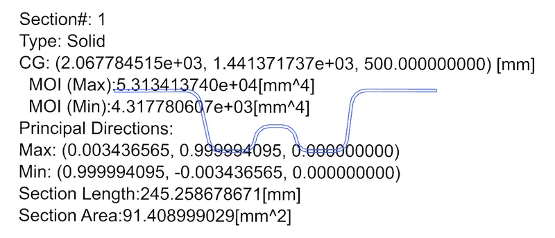
The section inertia analysis of center roof rail,
Assembly:
The assembly of the roof is as below
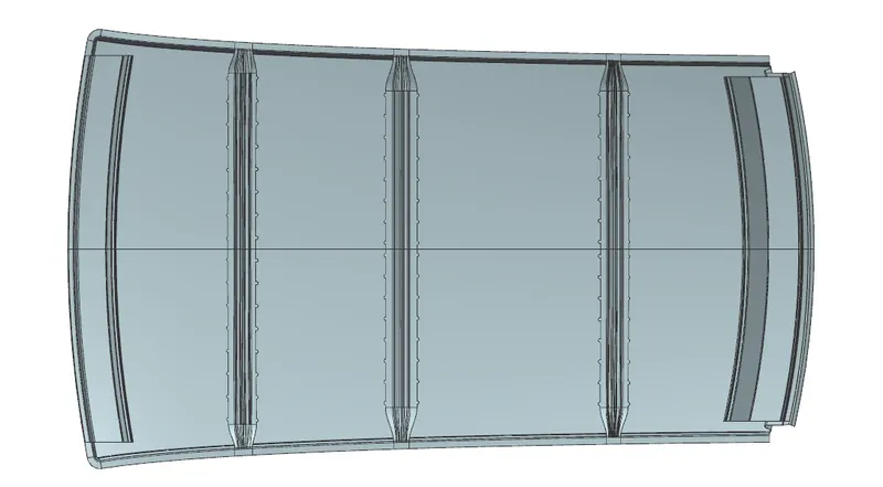
Curvature study of the assembly:
Heat Distortion Calculations:
Heat distortion is given by the formula,
W = [1.73 x 10^(-3) x L] + [1.85 x 10^(-8) x (R^2)/t] + [ 1.10x10^(-3) x l] - 2.68
Where,
L = Roof Length in X-Direction[mm](Roof dimension in 0-Y)
R = Roof curvature
R = 2(Rx*Ry)/(Rx+Ry)
Rx = X curvature
Ry = Y curvature
t = Roof plate thickness [mm]
l = Bow Roof Span [mm]
If W > 2.7 , then the result is OK.
Procedure to get the Rx, Ry Values
- Create a sketch, in which draw the 0Y line.
- Offset the line to 300mm, which is the 3Y line.
- Offset the 3Y line to 100mm symmetrically.
- Draw a vertical line in the center of the reinforcements and also offset them 100mm symmetrically.
- Plot the intersection points of these lines.
- Project the points to the roof surface.
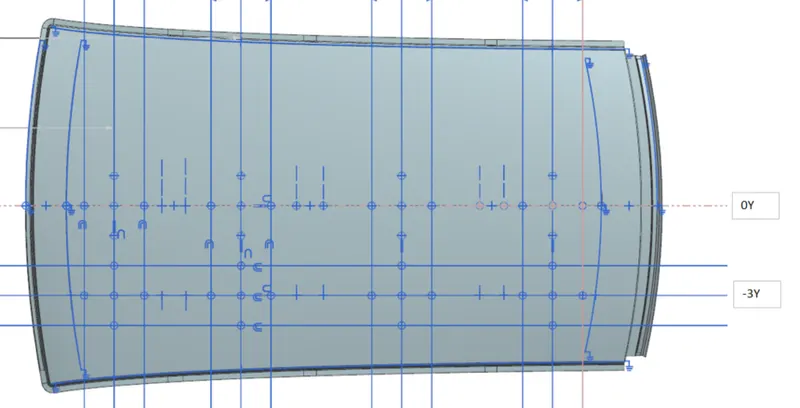
After projection of the points
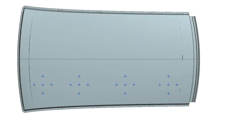
The values Rx & Ry can be taken by connecting the points. Arc with three points can be used.
| S.No | Case | L | Rx | Ry | R | t | l | W | Result |
| 1 | Front roof rail to Bow roof 1 | 2043.85 | 5741.29 | 2427.54 | 3412.291 | 0.75 | 303.99 | 1.477461 | OK |
| 2 | Bow roof 1 to center roof rail | 2043.85 | 5102.88 | 5668.78 | 5370.965 | 0.75 | 368.63 | 1.972919 | OK |
| 3 | Center roof rail to Bow roof 2 | 2043.85 | 4050.77 | 10211.21 | 5800.494 | 0.75 | 521.13 | 2.259031 | OK |
| 4 | Bow roof 2 to Rear roof rail | 2043.85 | 3281.83 | 14577.43 | 5357.517 | 0.75 | 304.85 | 1.899203 | OK |
Here, all the values are <2.7, hence all are OK.
Snow Load Calculations:
Snow load calculations is given by the formula,
Qr = [Iy x t2] / [α x s x [(Rx + Ry)/2]2 x 10-8]
Where,
α = My x Lx2 x 10-12 , My = Y(Ly-Y)
t = Roof plate thickness [mm]
Ly = Distance between the front and rear roof Rails on the Vehicle along with 0Y[mm]
Length of Roof panel with the center point between Roof rail Front /Rear as the front and rear reference point.
Lx = Distance between the Left and Right end of the roof on the Roof BOW [mm]
The width of the roof panel is exposed on the surface.
Y = Distance front Front Roof Rail to Roof BOW[mm]
s = Distance for which Roof BOW bears divided load [mm]
s = L1/2 + L2/2
Iy = Geometrical moment of inertia of Roof BOW (Y cross-section )[mm4]
Rx = Lateral direction curvature radius of roof panel Y cross-section on Roof BOW [mm]
Roof panel curvature Radius of the Length Lx in Front view
Ry = Longitudinal Direction curvature radius of the Roof panel X cross-section on Roof BOW [mm]
Roof panel X curvature radius of length s in Side view
- Create a sketch and draw the 0Y line.
- Offset the 0Y line 100mm on both sides.
- Draw a vertical line in the center of the reinforcements and also offset them 100mm symmetrically.
- Plot the intersection points.
- Project the points on the roof.
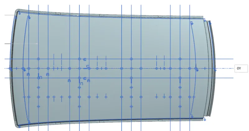
After the projection of the points,
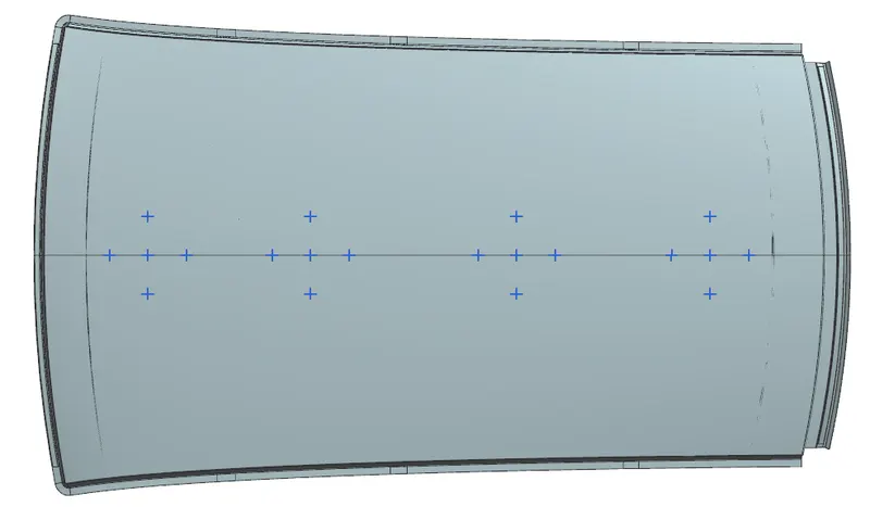
Measure the values of Rx & Ry similar to the previous one.
| S.No | Case | Rx | Ry | Lx | Ly | L1 | L2 | Y | My | s | α | t | Iy | Qr | Result |
| 1 | Front roof rail to Bow roof 1 | 4606.21 | 2495.68 | 1143.89 | 1943.12 | 424.91 | 454.03 | 424.91 | 645102.6 | 439.47 | 0.844107 | 0.75 | 3004.8 | 36.13463 | OK |
| 2 | Bow roof 1 to center roof rail | 3753.73 | 5567.78 | 1095.31 | 1943.12 | 454.03 | 606.7 | 878.94 | 935350.4 | 530.365 | 1.122144 | 0.75 | 4317.78 | 18.78656 | OK |
| 3 | Center roof rail to Bow roof 2 | 4239.07 | 10629.86 | 1063.43 | 1943.12 | 606.7 | 457.47 | 1485.64 | 679650.6 | 532.085 | 0.768606 | 0.75 | 3020.58 | 7.516729 | OK |
| 4 | Bow roof 2 to Rear roof rail | 4008.98 | 16379.78 | 1047.3 | 1943.12 | 1943.12 | 0 | 0 | 0 | 0.75 | #DIV/0! |
Here, the values of Qr is >3.1, Hence it is OK.
For the 4th region, L2 cannot be determined hence Qr cannot be calculated.
Conclusion:
The roof assembly is designed with A surface and the master section provided. The assembly is created with required front and rear roof rails and also the center and bow roof rails. Draft angle of minimum 7 degrees is provided in all the parts. And, the curvature study is also done for Heat distortion and Snow load. The results obtained are satisfactory.