Roof Design
OBJECTIVE:
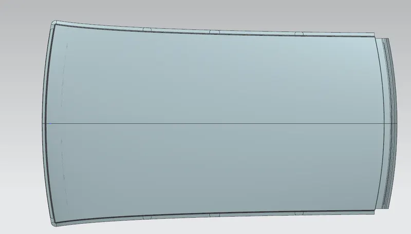
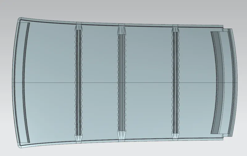
- The objective of this project is to design roof with flanges and reinforcements like ditch area, front roof rail, bow roofs, centre roof rail and rear roof rail using the given surface.
- To Perform the calculations for heat distortion and snow load criteria.
- Perform the draft analysis for each reinforcements
INTRODUCTION:
An automobile roof top is the portion of an automobile that sits above the passenger compartment, protecting the vehicle occupants from sun, wind, rain, and other external elements.

ROOF CRUSH TEST:
In OEM's paasenger safety plays a majore role. To achieve this the strength of a car is crased and tested when a new model is launched.
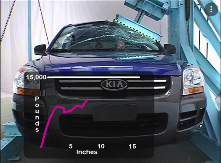
The strength of the roof structure while crashing in the real world condition the maximum moving distance of the roof structure should be less than 127mm and the load acting is 1.5 times the vehicle weight.
The below link shows the crash video and how it is performed.
https://www.youtube.com/watch?v=APgPScmeSaA
During the test, It is conducted on the either side of the roof structure, the front left or front right or both in a single test. The rigid plate should not move faster than 0.5inches per second and the force acting should not be less than 1.5 times the unloaded vehicle weight.
Rollover accidents of a car are the most occurring accidents that we see in our daily lives. The passengers experience major injuries like neck, head and spine injuries. So, to reduce the injuries of a passenger from major fatalities it is important to provide safety in the car. Though safety is provided by seat belts and airbags during accidents, the passenger must have sufficient space for survival in the car during accidents. The roof of the car must have high strength to resist the crush force to avail the passenger some space for survival.
DESIGN CONSIDERATION FOR A ROOF:
- Visibility criteria
- Head clearance
- Curvature study
- Heat distortion and snow load criteria
- Draft analysis.
CALCULATIONS:
HEAT DISTORTION :
W = [1.73 x 10^(-3) x L] + [1.85 x 10^(-8) x (R^2)/t] + [ 1.10x10^(-3) x l] - 2.68
Where,
L = Roof Length in X-Direction[mm](Roof dimension in 0-Y)
R = Roof curvature
R = 2(Rx*Ry)/(Rx+Ry)
Rx = X curvature
Ry = Y curvature
t = Roof plate thickness [mm]
l = Bow Roof Span [mm]
CONDITION:
OK< 2.7
PROCEDURE FOR HEAT DISTORTION CALCULATION:
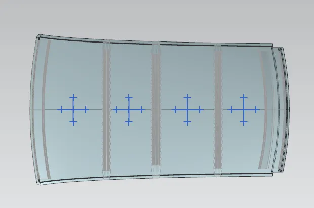
In roof the centre 0-y line or parting line if offseted to a distance of 300 mm and the 300mm offseted line is symmetrically offsetted for 100mm
In x axis the centre line are calculated based on the arc percentage of the reinforcent linke bow roof1,bow roof2 and centre roof . so the line lies between them and these lines are offseted symmetrically 100mm.
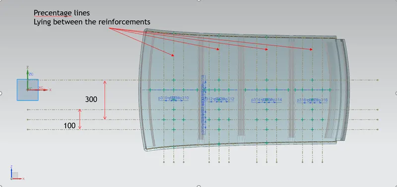
By using these line the inte section points are created and they are projected on the surface of the roof.
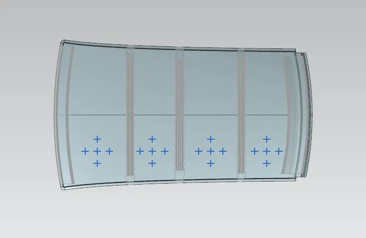
By using these points and 3point arc method the arcs are created and Rx and Ry value are calculated.
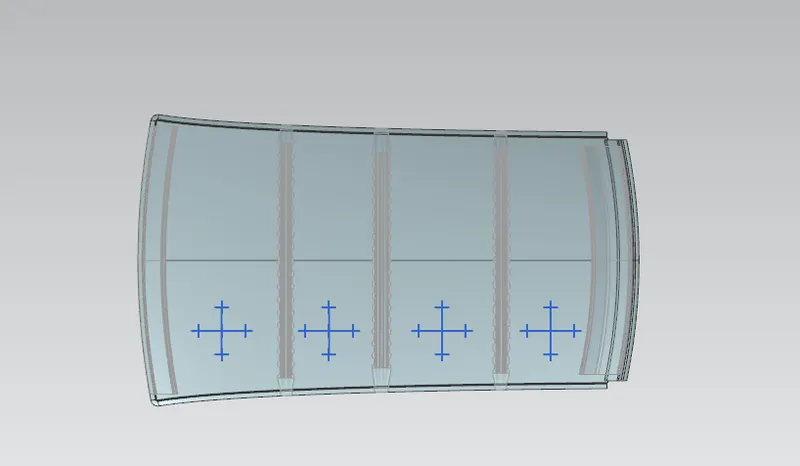
By calulating all the values and using the above give formula. the values must be accepted for the given condition OK< 2.7.

SNOW LOAD CONDITION:
Qr = [Iy x t2] / [α x s x [(Rx + Ry)/2]2 x 10-8]
Note: The Qr value given over here is correct. There was a typo error in the formula given in the video.
Where,
α = My x Lx2 x 10-12 , My = Y(Ly-Y)
t = Roof plate thickness [mm]
Ly = Distance between the front and rear roof Rails on the Vehicle along with 0Y[mm]
Length of Roof panel with the center point between Roof rail Front /Rear as the front and rear reference point.
Lx = Distance between the Left and Right end of the roof on the Roof BOW [mm]
The width of the roof panel is exposed on the surface.
Y = Distance front Front Roof Rail to Roof BOW[mm]
s = Distance for which Roof BOW bears divided load [mm]
s = L1/2 + L2/2
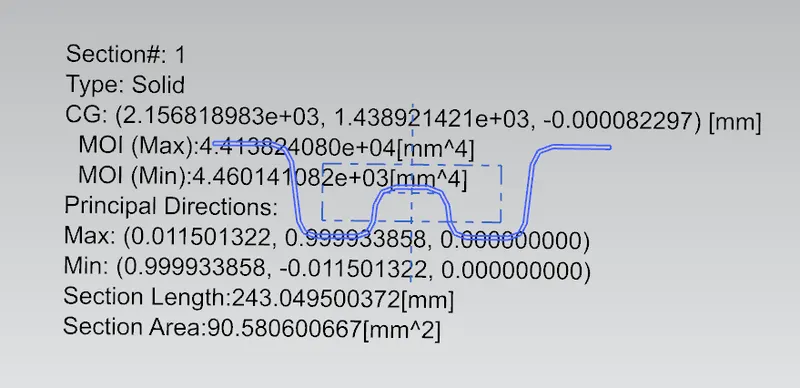
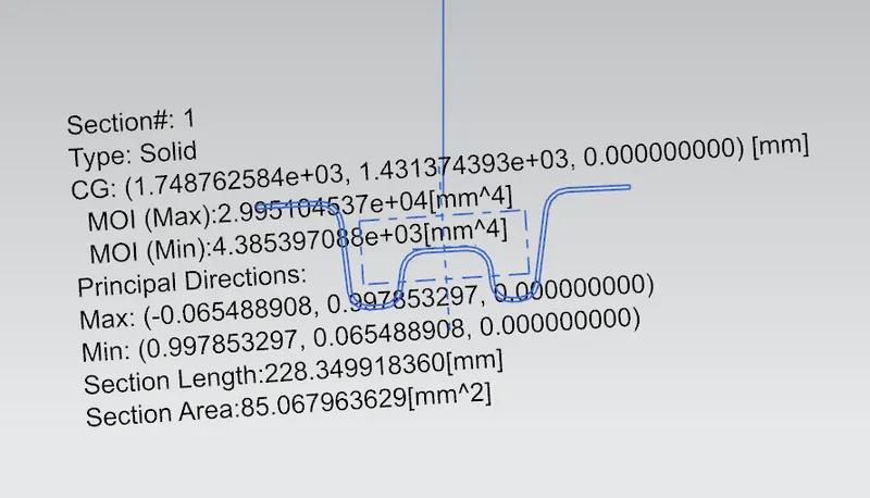
Iy = Geometrical moment of inertia of Roof BOW (Y cross-section )[mm4]
Rx = Lateral direction curvature radius of roof panel Y cross-section on Roof BOW [mm]
Roof panel curvature Radius of the Length Lx in Front view
Ry = Longitudinal Direction curvature radius of the Roof panel X cross-section on Roof BOW [mm]
Roof panel X curvature radius of length s in Side view
CONDITION:
Qr ≥ 3.1
PROCEDURE:
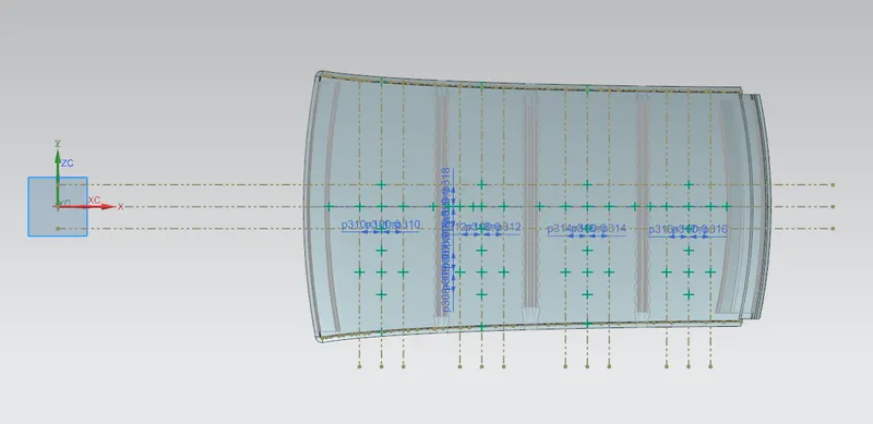
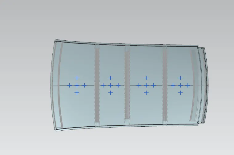
By using the above procedure for the creating sketches and points.
the line position is different like. the centre line lise in the centre parting line and offset for 100mm are made symmetrically.
the x line are created as per the precious procedure and the points are created and arcs is drawn.
iNERTIA CALCULATION:
CENTRE ROOF RAIL:
BOW ROOF 1:
BOW ROOF 2:
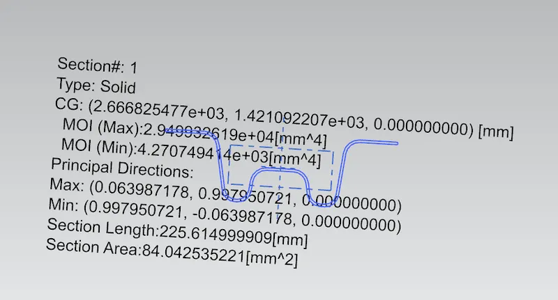
By calcualting all the values and using the formula and the values must pass the condition
Qr ≥ 3.1

DRAFT ANALYSIS:
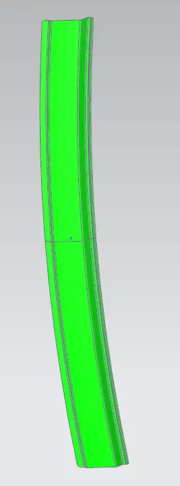
In Draft analysis the tooling direction is drawn by using the line connecting the end points of the reinforcement and the mid point of the line is selected and perpendicular line is drawn and this perpendicular line is the tooling direction.
The reinforcement are checked with the tool opening of 7 degrees.
FRONT ROOF RAIL:
BOW ROOF 1:

CENTRE ROOF RAIL:

BOW ROOF 2:

REAR ROOF RAIL:
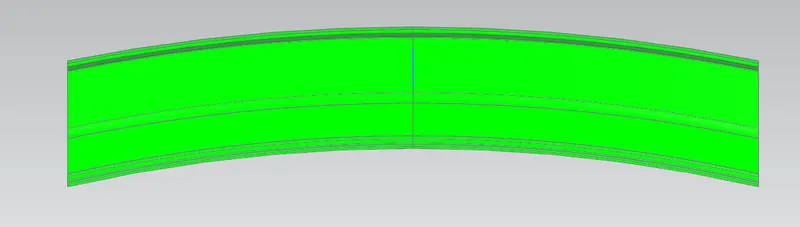
The full green represent all the surfaces are good for draft analysis.
If there is any change of colour in surface like yellow, red and blue. The draft angle can be increased and green can be achieved.
MANUFACTURING TECHNIQUES:
FORMING:
Forming is the operation of deforming a part in curved profile. Forming tools apply more complex forms to work pieces. The line of bend is curved instead of straight and the metal is subjected to plastic flow or deformation.
Piercing Operations
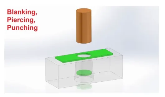
As indicated in the figure, piercing is the process of creating desired shape holes in a piece of sheet metal without taking any material from the sheet or removing a very little quantity of material. In this operation, both punch and die are used. Bullet-shaped punches are commonly employed in piercing operations.
Drawing Operations
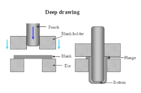
It is the process of fabricating thin-walled hollows or vessel-shaped pieces out of sheet metal. It can be classified into two groups:
Deep drawing – the object to be drawn has a depth that is greater than its breadth.
Shallow drawing – the item to be drawn has a length that is less than its width. Pans, tubes, and cams are instances of drawing.
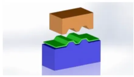
Embossing Operations
It’s a metalworking technique for creating raised surfaces or letters in sheet metal. During this operation, the thickness of the metal does not change.
Bending Operations
When forces are applied to certain regions, this happens. With the inner surface under compression and the outer surface in tension, the metal flow is uniform along the bend axis. The following are the various types of sheet metal bending operations:
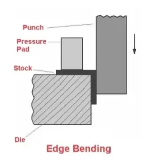
Edge bending
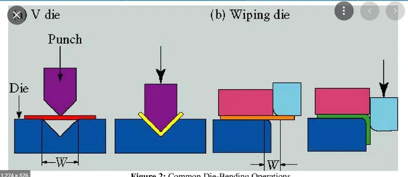
As indicated in the diagram, it is a type of bending operation in which a piece of sheet metal is fixed or held between two dies from one end. The other end is thus compelled to strike the free or unfixed punch. To complete the shaping process, the sheet metal piece’s free or unfixed edge is bent.
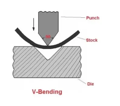
V-bending
When a piece of sheet metal is squeezed between the die and the punch in this type of bending operation, it is shaped into a V-shape in the die.
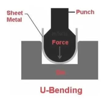
U-bending
The sheet metal component is shaped into a U-shape in this type of bending operation, in which the punch is forced into the die by a force.
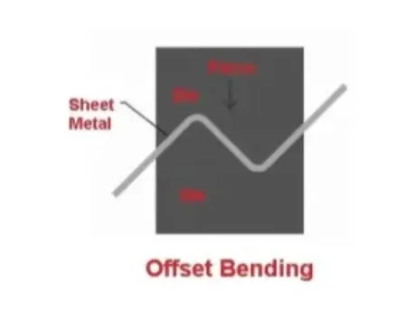
Offset bending
It is a type of bending operation in which a piece of sheet metal is punched and die-formed into an offset shape.
Final Images: