Roof Design
Roof Design
OBJECTIVES:
Create a roof of the car by the given styling surfac based on the master section provided.
To validate the designed roof is satisfy the heat distortion criteria and snow load condition.
ROOF INTRODUCTION:
An automobile roof or car top is the portion of an automobile that sits above the passenger compartment, protecting the vehicle occupants from sun, wind, rain, and other external elements. The roof must be design in such a way that it would able to withstand any load or impact due to accidents or objects falling on it and other envirmental factor.
The design based on the standards and design intent which make the roof to withstand the above-said conditions.The roof is an assembly of many parts like front roof rail, bow roof , bow roof center and reinforcement center. The number of bow roof is based on the length of the roof and some time bow roof center is avoided in case like small car. the roof is attached to the body of the car using mastic sealants provided between bow roof and the front or rear roof rail.
Roof is connected to A-pillar,B-pillar and C-pillar to cover the front and rear door. roof is spported by reinforacment bow-roof with front and back roof rail.
Types of roof reinforacment are as follow:-
Front roof rail
Center roof rail
Front bow roof rail
Rear bow roof rail
Rear roof rail
DITCH AREA:
It is long narrow hole that has been seen like dug into the roof. It is the extended portion of the main roof concealed by other BIW panels and not a styling surface. Headroom clearance .visibility criteria, clearance for windshield and back door are some of the factors to be considered while designing the ditch area.
Spot welding:-
Spot welding (RSW) is an electrical resistance welding process that joins overlapping metals between two electrodes. Pressure is applied by squeezing the workpieces between the electrodes and heat is generated by the passage of welding current through the resistive metals. Roof outer suraface and the bow roof rails are join by spot welding process.
FRONT ROOF RAIL:
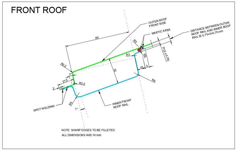
It is the support that is joined with the windshield glass,bodyside outer and the inner panels. It is usually made from body side outer scrap and therefor the thickness of the rail is 0.75mm. The visibility criteria and the headroom clearance of the passenger are taken into consideration for the bottommost flange. Windshield end and the roof end are spot welded and the other end of the front roof rail is joined with the roof using mastic sealants for increase strength.
RAER ROOF RAIL:
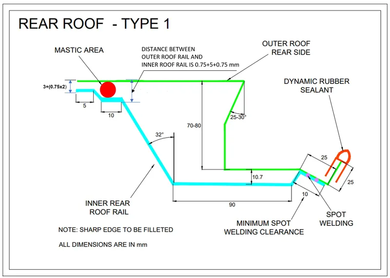
It is the support that is joined to the backdoor, the bodyside outer and the inner panels. Inputs from the backdoor design is also taken to accommodate the required clearance along with headroom clearance and the rear visibility criteria while designing the rear roof rail.
CENTRE ROOF RAIL AND BOW ROOFS:
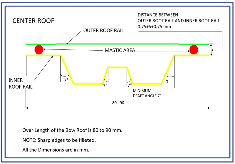
Similar to other roof rail designs,we have to take into consideration the headroom clearance while designing the centre roof rail and bow roofs. Unlike the front and rear roof rails,spot welds are not applied for joining these rails to the roof. Mastic sealants are introduced at both the ends instead of spot welds since centre roof rail and row roof are fully positioned under the styling surface of the roof.
CENTRE ROOF RAIL
BOW ROOF 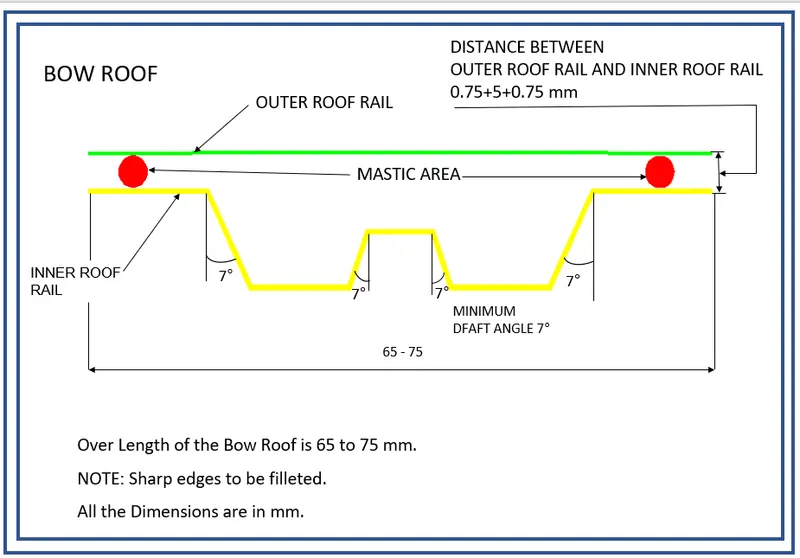
Bow–Roof Prediction
Heat Distortion criteria:
Uneven temperatures (or thermal gradients) create stresses within the metal itself, and these stresses will create distortion. Repeated cycling through thermal gradients can also result in thermal fatigue cracking. The poor thermal conductivity of stainless steels contributes to larger thermal gradients.
Heat distortion in roof is the temperature at which the metal softens and forms under a specific load. This study is done to check the ability of the roof to withstand high temperature with respect to the positioning of the reinforcements which contribute to increased strength.The heat distortion study plays a major role in sheet metal urges. Heat distortion in roof is a temperature limit above which the material cannot be used for structural applications. This study is used to predict the heat distortion temperature at where the material starts to soften when exposed to a fixed load at an elevated temperature. To avoid bending or damage to the roof, based on the heat distortion temperature, this study will predict the bow roof position which helps to strengthen the roof.
W = [1.73 x 10^(-3) x L] + [1.85 x 10^(-8) x (R^2)/t] + [ 1.10x10^(-3) x l] - 2.68
Where,
L = Roof Length in X-Direction[mm](Roof dimension in 0-Y)
R = Roof curvature
R = 2(Rx*Ry)/(Rx+Ry)
Rx = X curvature
Ry = Y curvature
t = Roof plate thickness [mm]
l = Bow Roof Span [mm]
Judgment Condition
OK< 2.7
FINAL IMAGE OF THE ROOF:
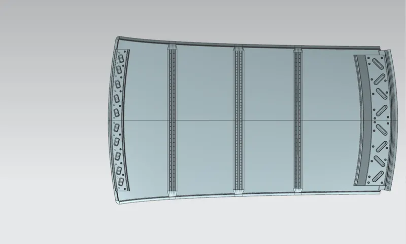
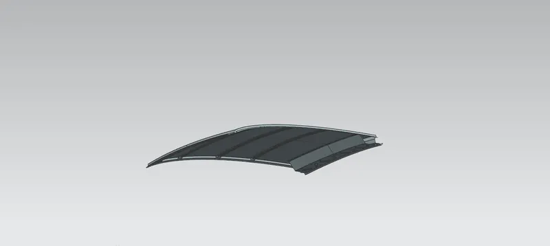
Here we have to find out the RX and Ry values. To find that:
Create a sketh on top roof and drawn a horizontal line at the centre.
Then offset this line below 300mm and called it as -3Y line.
From the _3Y line offset 100 mm above and below and convert all these line into refernece lines.
Draw the verical lines at the middle of the each reinforcemnts and offset it to 100 mm both sides.
Intersection point is created where the lines are met.
Project these points to the outer roof panel.
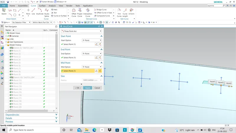
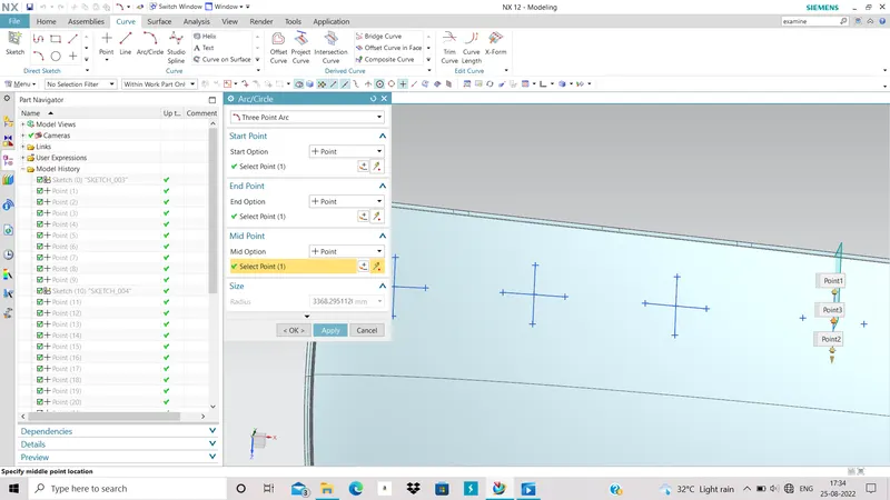
For Bow Roof Span [mm]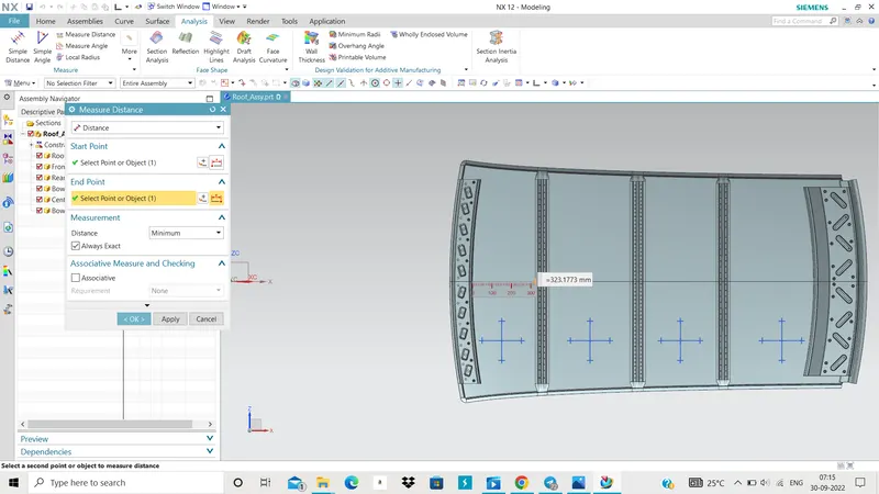
same for the other calculation we have to do that.
Roof plate thickness 0.75 [mm]
| Sr. No. | Bow Roof | L= Roof Length[mm] | Rx= X Curvature [mm] |
Ry= Y Curvature [mm] |
I= Bow Roof Span[mm] | R= 2(Rx*Ry)/(Rx+Ry) |
W= [1.73 x 10^(-3) x L] + [1.85 x 10^(-8) x (R^2)/t] + [ 1.10x10^(-3) x l] - 2.68 |
Judgment Condition OK< 2.7 |
| 1 | Front roof rail - Front bow roof rail |
2033.70 | 2332.78 | 5729.36 | 323.17 | 3315.58 | 1.46 | Ok |
| 2 | Front bow roof rail-Center roof rail | 2033.70 | 5650.51 | 5103.77 | 411.78 | 5363.24 | 2.01 | Ok |
| 3 | Center roof rail- Rear bow roof rail | 2033.70 | 9539.22 | 4186.002 | 359.99 | 5818.65 | 2.07 | Ok |
| 4 | Rear bow roof rail-Rear roof rail | 2033.70 | 14001.64 | 3368.29 | 424.45 | 5430.25 | 2.03 | Ok |
2. Snow Load Criteria:
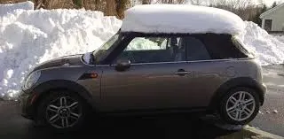
Snow load criteria study is done to check the ability of the roof to withstand snowfall and bounce back to its original shape without any permanent deformation on the load is removed.
Snow Load Prediction Formula
Qr = [Iy x t2] / [α x s x [(Rx + Ry)/2]2 x 10-8]
Where,
α = My x Lx2 x 10-12 , My = Y(Ly-Y)
t = Roof plate thickness [mm]
Ly = Distance between the front and rear roof Rails on the Vehicle along with 0Y[mm]
Length of Roof panel with the center point between Roof rail Front /Rear as the front and rear reference point.
Lx = Distance between the Left and Right end of the roof on the Roof BOW [mm]
The width of the roof panel is exposed on the surface.
Y = Distance front Front Roof Rail to Roof BOW[mm]
s = Distance for which Roof BOW bears divided load [mm]
s = L1/2 + L2/2
Iy = Geometrical moment of inertia of Roof BOW (Y cross-section )[mm4]
Rx = Lateral direction curvature radius of roof panel Y cross-section on Roof BOW [mm]
Roof panel curvature Radius of the Length Lx in Front view
Ry = Longitudinal Direction curvature radius of the Roof panel X cross-section on Roof BOW [mm]
Roof panel X curvature radius of length s in Side view
For Rx and Ry
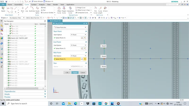
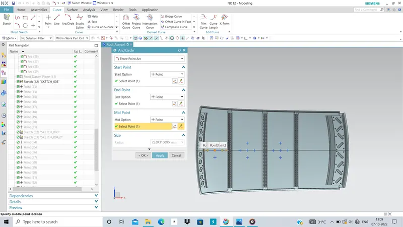
Distance for which Roof BOW bears divided load [mm]
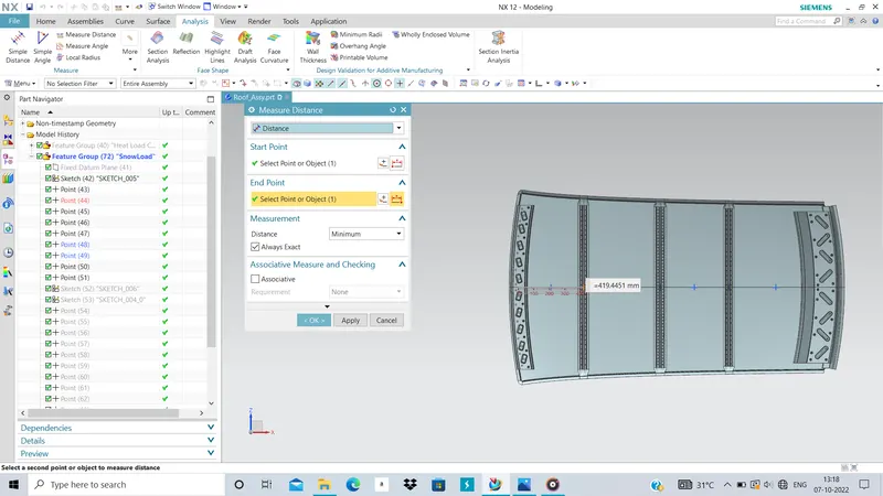
Distance front Front Roof Rail to Roof BOW[mm]

| Sr. No. | Bow Roof Rail | L1[mm] | L2[mm] |
| 1 | Front Bow Roof Rail | 419.445 | 486.73 |
| 2 | Center Roof Rail | 486.73 | 434.98 |
| 3 | Rear Bow Roof Rail | 434.98 | 599.58 |
For Lx and Ly
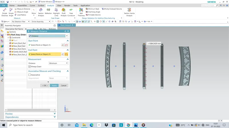
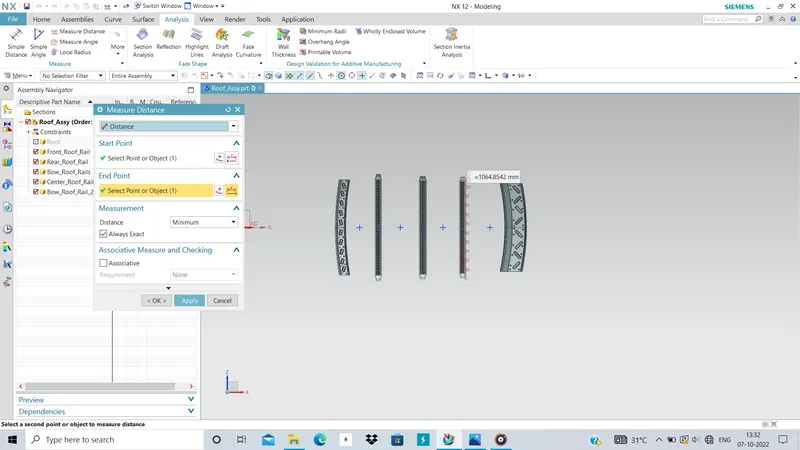
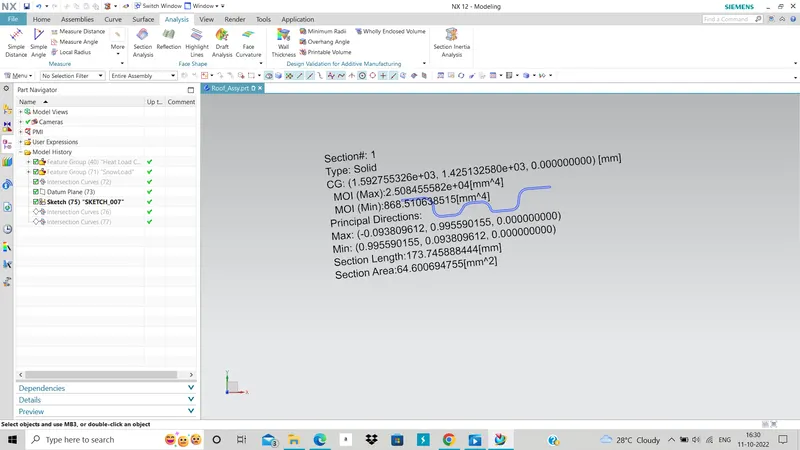
Geometrical moment of inertia of Roof BOW :
BOW ROOF 1:
CENTRE ROOF RAIL:
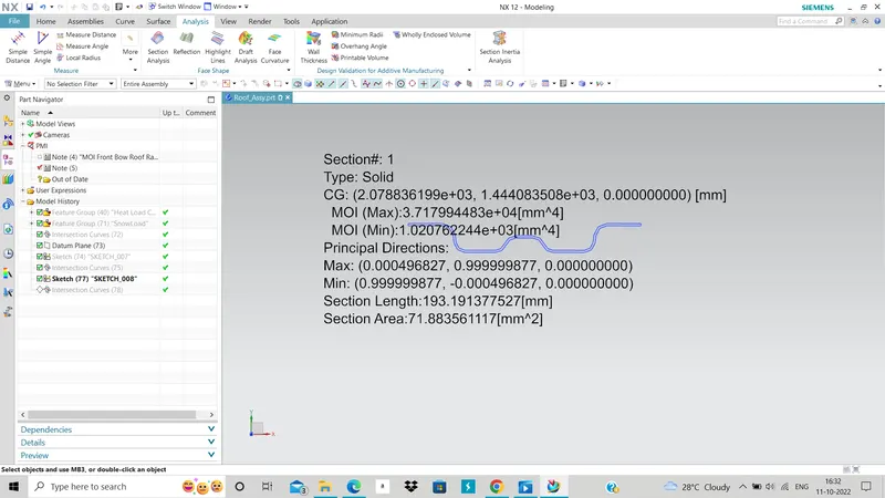
BOW ROOF 2:
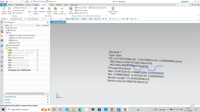
| Sr. No. | Bow Roof Rail | Rx= X Curvature [mm] |
Ry= Y Curvature [mm] |
α = My x Lx2 x 10-12 , My = Y(Ly-Y) |
Lx [mm] | Ly[mm] | Y [mm] |
s = L1/2 + L2/2 |
Iy [mm4] | Qr = [Iy x t2] / [α x s x [(Rx + Ry)/2]2 x 10-8] |
Judgment condition Qr ≥ 3.1 |
| 1 | Front Bow Roof Rail | 4724.9 | 2320.3 | 0.799 | 1124.15 | 1928.30 | 419.445 | 448.08 | 868.510683515 | 10.99 | Ok |
| 2 | Center Roof Rail | 3753.2 | 4577.85 | 1.089 | 1084.54 | 1928.30 | 903.575 | 460.85 | 1.020762244E+03 | 6.59 | Ok |
| 3 | Rear Bow Roof Rail | 6241.2 | 4158.66 | 0.897 | 1064.85 | 1928.30 | 1335.85 | 517.28 | 869.813434475 | 3.89 | Ok |
Draft Analysis :-
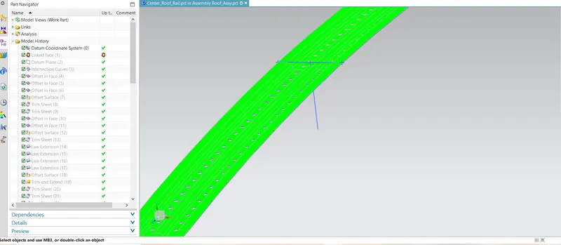
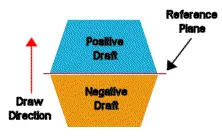
The Draft Analysis enables you to detect if the part you drafted will be easily removed. This type of analysis is performed based on color ranges identifying zones on the analyzed element where the deviation from the draft direction at any point, corresponds to specified values.
No parts can be ejected from the tool if it is having a straight 90-degree profile from its base surface. A small draft angle is provided to each and every area of the component in order to get easy removal of the component from the tool.
Draft angle :-
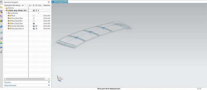
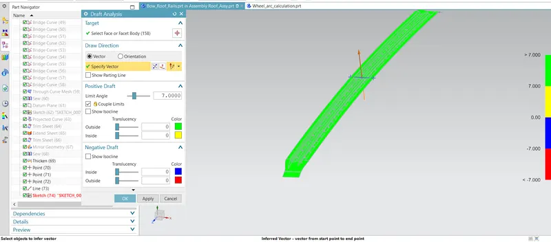
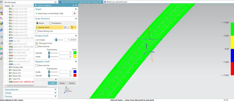
Front bow roof rail
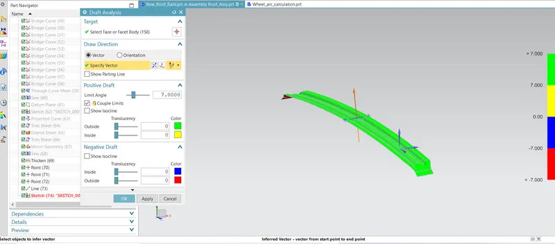
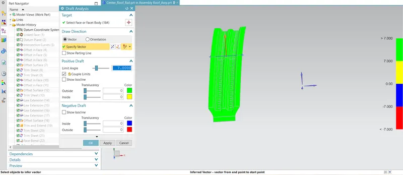
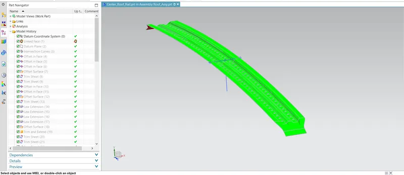
Center roof rail
Rear bow roof rail
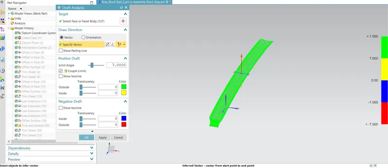
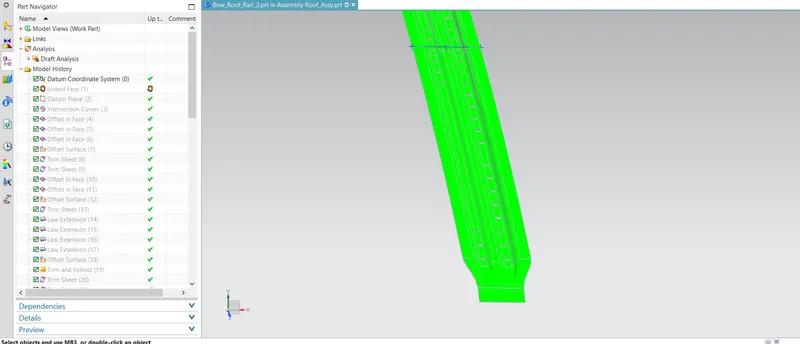
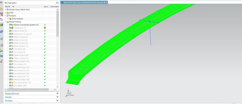
To analysis the draft for the bow roof it should be more than 7 degree in this draft analysis result shown in different colours so that we can easily understand.Draft is divided into two parts as positive and negative draft.
Positive Draft.
>7.0 It shown in Green.
7.0>0 It shown in Yellow.
Negative Draft.
0>-7.0 It shown in Blue.
<-7.0 It shown in Red.
If we get the result in different colour other than green then we have to check the draft angle of that side or surface so that we can get the result in the all part in the green. It means this bow roof rail are manufactured by the tools easily with standard method.