Roof Design
-Design Considerations:
Visibility criteria
Head Clearance
Heat Distortion criteria
Snow Load criteria
Drafts
-Componenets Of Roof:
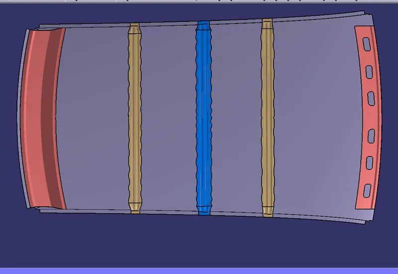
(From Extreme left)
1: Front Roof Rail:
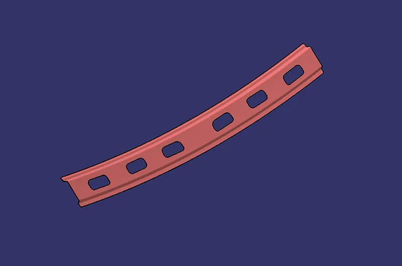
The front roof rail is located on the front of the roof where the wind shield joins with the roof. The visibility criteria and the head room clearance of the passenger are taken into consideration for the bottom flange.
2. Bow Roof 1:
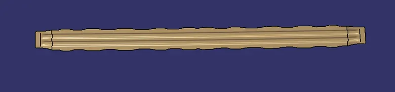
Bow roof is an additional siffening member for the roof to increase the strength.
3. Center Roof Rail:
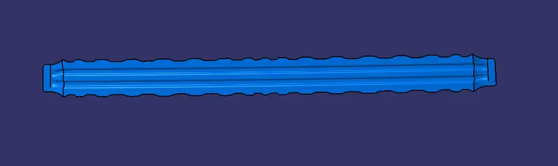
Centre Roof rail or the reinforcement centre is located at the centre of the roof .
4. Bow Roof 2:
It is given when the lengh of the roof is more.
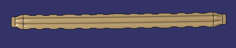
5. Rear Roof Rail:
Centre Roof rail or the reinforcement centre is located at the centre of the roof .
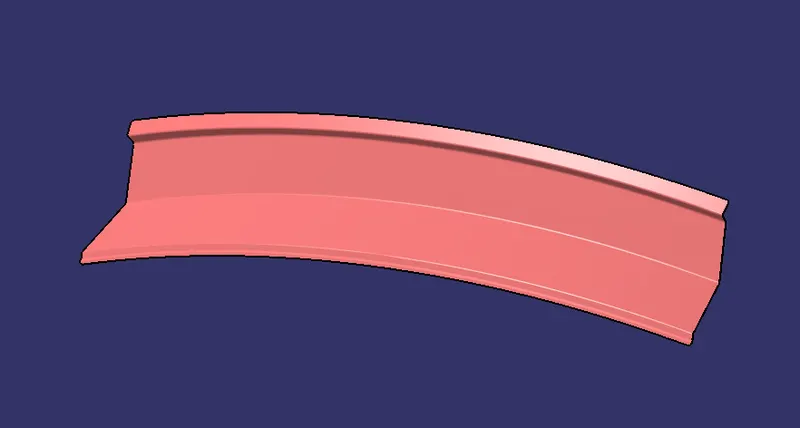
6. Top Of the Roof:
This is the main part of the roof. It cover the vehicle from the top and provides housing to the passengers. It withstand all the heat and load coming from outer side of the vehicle.
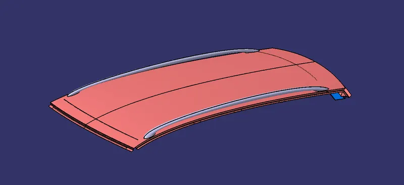
- Draft analysis-
Before we give the part for manufacturing we have to check some analysis ourself to check all the constraints and to check if we have any negative draft on a part .
As we know that we need to give our parts proper drafts so that they can be easily manufactured.
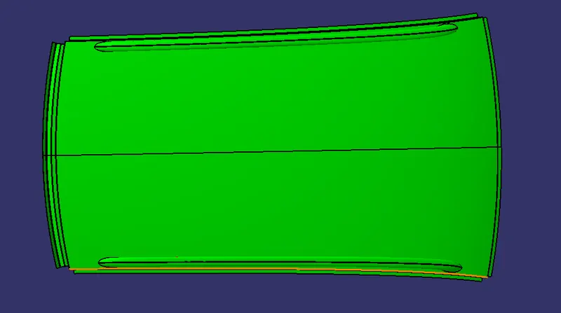
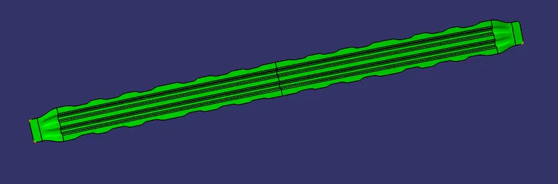
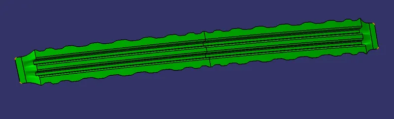
The green colour shows positive draft area.
Blue colour shows negative draft area.
ROOF:
Front Roof RAIL:
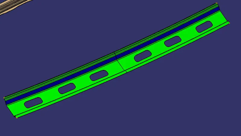
We can clearly see that there are some negative draft on this part. We well have to inform this to out manufacturing team. Or we can modify out initial design to avoide further errors.
Bow roof 1&2:
Center Roof RAIL:
Rear Roof Rail:
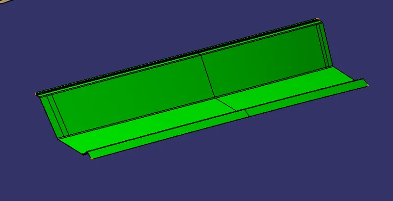
SO, as shown in the images. Every part should be having proper drafts.
Here we have tried to give at least 3 degree draft in out parts.
CALCULATIONS
-Bow–Roof Prediction Formula
W = [1.73 x 10^(-3) x L] + [1.85 x 10^(-8) x (R^2)/t] + [ 1.10x10^(-3) x l] - 2.68
Where,
L = Roof Length in X-Direction[mm](Roof dimension in 0-Y)
R = Roof curvature
R = 2(Rx*Ry)/(Rx+Ry)
Rx = X curvature
Ry = Y curvature
t = Roof plate thickness [mm]
l = Bow Roof Span [mm]
Heat Distosions: It is measured to calculate the heat impacting on the roof of a vehicle. As it is mostlty going to be facing the sunlight, it should be designed in such a way that the heat of the sun does not imapct the inner body the roof and designs. Thus we calculate this. .
Formula-
W = [1.73 x 10^(-3) x L] + [1.85 x 10^(-8) x (R^2)/t] + [ 1.10x10^(-3) x l] - 2.68
| Position | Rx | Ry | R | l | L | t | R^2/t | W | OK/NOK |
| FR & Bow 1 | 3393 | 13852 | 5450 | 418 | 2035 | 1.5 | 39603333.3 | 2.0318 | OK |
| Bow 1 & CR | 4085 | 10031 | 5805 | 285 | 2035 | 1.5 | 44930700 | 1.98 | OK |
| CR & Bow 2 | 4843 | 6711 | 5625 | 314 | 2035 | 1.5 | 42187500 | 1.934 | OK |
| Bow 2 & RR | 5698 | 1883 | 2830 | 418 | 2035 | 1.5 | 10678533.33 | 1.3973 | OK |
Judgment Condition
OK< 2.7
So, given by the judgement conditions. We can say that our roof design is okay.
Snow Load criteria:
In many regions, where snowfall occurs. In such regions we need to take care of the load of the snow which falls on the roof of the vehicle.
Our roof should be designed in such a way that when the snow falls on the roof then the roof should be withstanding the load impacted on it. Also, when the snow is removed from the roof, the roof should take its prvious shape as well.
Snow Load Prediction Formula
Qr = [Iy x t2] / [α x s x [(Rx + Ry)/2]2 x 10-8]
Note: The Qr value given over here is correct. There was a typo error in the formula given in the video.
Where,
α = My x Lx2 x 10-12 , My = Y(Ly-Y)
t = Roof plate thickness [mm]
Ly = Distance between the front and rear roof Rails on the Vehicle along with 0Y[mm]
Length of Roof panel with the center point between Roof rail Front /Rear as the front and rear reference point.
Lx = Distance between the Left and Right end of the roof on the Roof BOW [mm]
The width of the roof panel is exposed on the surface.
Y = Distance front Front Roof Rail to Roof BOW[mm]
s = Distance for which Roof BOW bears divided load [mm]
s = L1/2 + L2/2
Iy = Geometrical moment of inertia of Roof BOW (Y cross-section )[mm4]
Rx = Lateral direction curvature radius of roof panel Y cross-section on Roof BOW [mm]
Roof panel curvature Radius of the Length Lx in Front view
Ry = Longitudinal Direction curvature radius of the Roof panel X cross-section on Roof BOW [mm]
| Bow Position | Iy | a | Lx | Ly | Y | s | Rx | Ry | Qr OK/NOK |
| FR & BOW 1 | 0.027 | 3.65 | 1198.8 | 1922.204 | 600.453 | 784.22 | 4324.668mm | 2925.221mm | 5.63 OK |
| BOW 1 & CR | 0.027 | 2.21 | 1100 | 1922.204 | 967.992 | 1166.203 | 3799.464mm | 6677.902mm | 10.6 OK |
| CR & BOW 2 | 0.027 | 1.236 | 1074 | 1922.204 | 1964.414 | 1643.309 | 4214.85mm | 10374.038mm | 16.2 OK |
| BOW 2 & RR | 0.027 | 0 | 1056 | 1922.204 | 1922.204 | 1922.204 | 4106.926mm | 15766.396mm | NA NA |
Judgement condition : Qr ≥ 3.1
SO, based on the calculations we can say that our design was okay and manufactureable.