Roof Design
Roof Design
Objective
To create an ASSEMBLY by developing the essential flanges for the outer roof and creating the reinforcements by following master section for the gven Roof styling. And also check for Draft analysis and do a curvature study on the roof and perform calculations to determine the position of the Bow-roofs.
INTRODUCTION
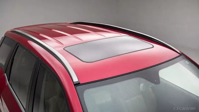
An automobile roof is the part of an automobile that placed above the passenger compartment and it protecting the vehicle occupants from sun, wind, rain, and other external elements. Some of the cars has sun roof and some have open roof system. Roof with sunroof is shown in the above fig. We used some of the reinforcement to increase the strength of the roof. The reinforcemnets are front roof rail, Rear roof rail, Reinforcement Centre roof rail and Bow roofs.
Master section used:
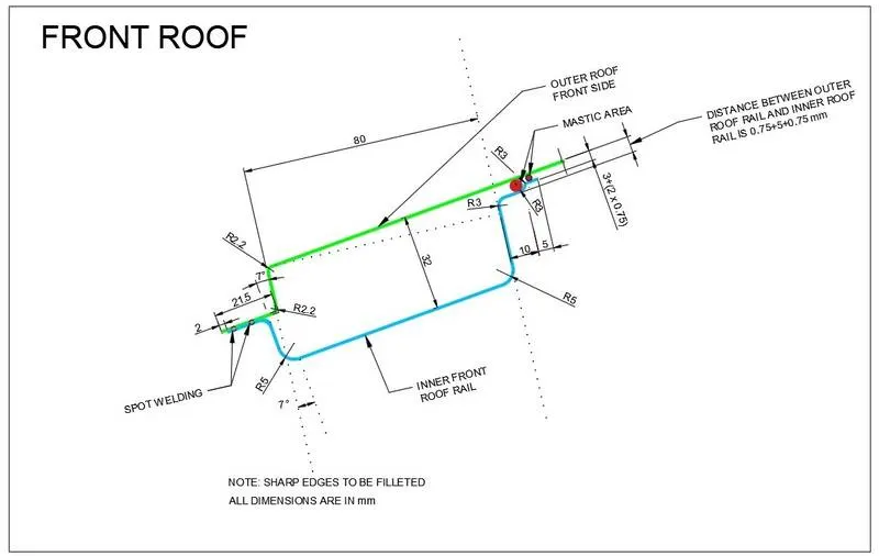
Front Roof Rail Master section
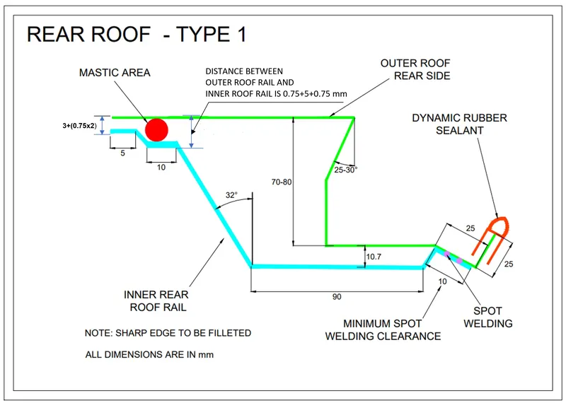
Master section of the Rear Roof Rail
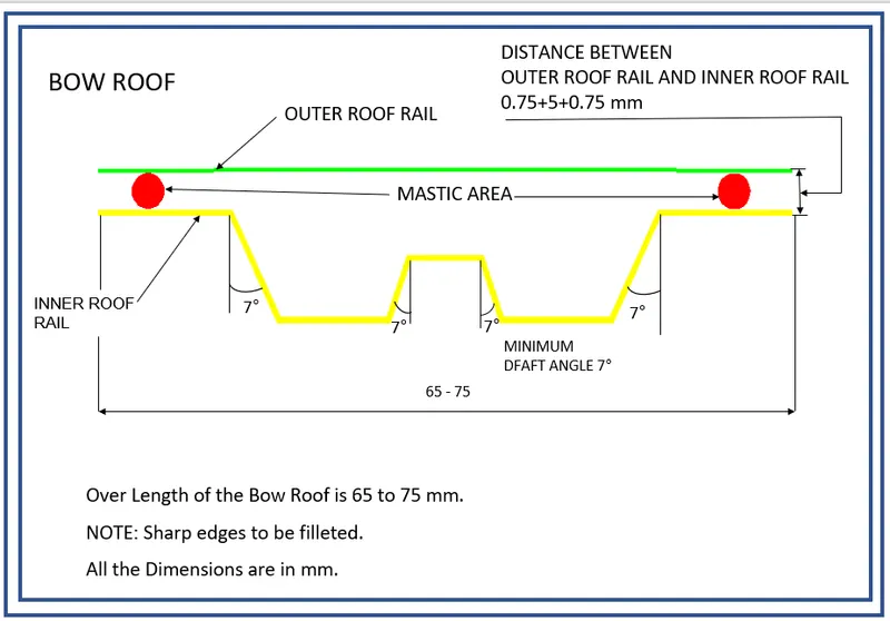
Master section of Bow Roof
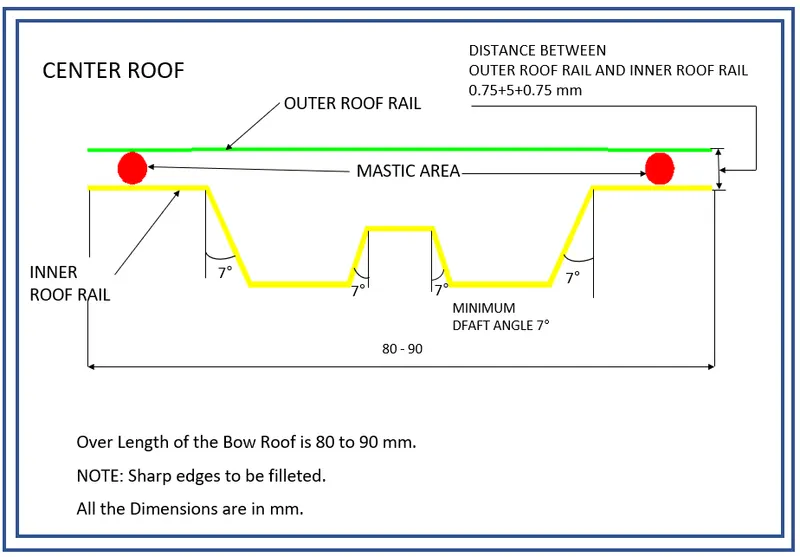
Master section of Center Reinforcement Rail
Roof design
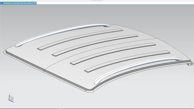
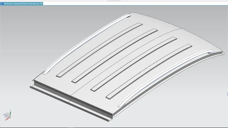
In this Roof design we created ditch area which is the extended portion of the outer roof it concealed by other BIW panels. This ditch area is designed by following the given master section and considered Headroom clearance, visibility criteria, clearance for windshield and backdoor during designing.
Front roof rail
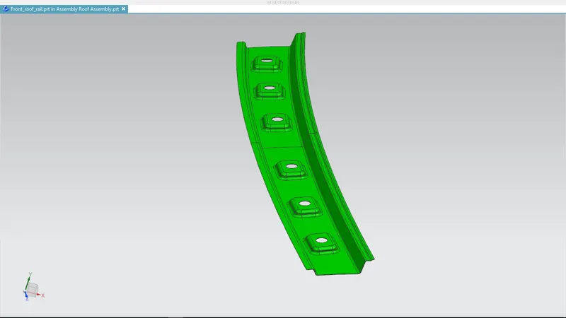
This is the first reinforcement of the roof which is placed in fornt end of the roof. We designed this Front roof reinforcement according to given master section and additionally we added emboss to increase the strength of the reinforcement. After designing we thicken it for 0.75mm.
Rear roof rail
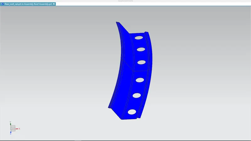
Here we designed Rear roof rail which is placed in the rear end of the roof outer panel. It is the rear reinforcement for the roof. In this rear roof rail we gave a clearence for the spot weld at the end of the reinforcement. We can spot weld at the end of the roof because it will be covered by back door. And also we gave a clearence for the mastic area in front side of the rear roof rail.
Centre reinforcement rail
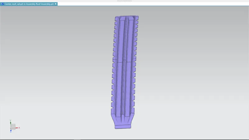 Here we designed centre roof rail which is placed in the centre of the Roof which helps to give the strength in the centre area of the roof. Here we only give a mastic sealent, we can't able to spot weld here because it will damage the aesthetic design of the roof outer panel. So, here we only use mastic sealent to attach centre roof rail and roof outer panel.
Bow roof 1 and Bow roof 2
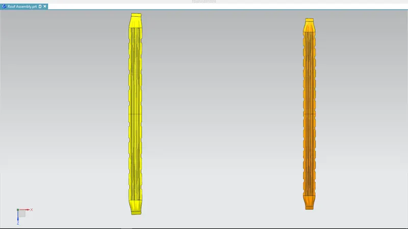
These Bow roofs are designed according to the given master section. Bow roof-1 is placed in between Front roof rail and the centre roof rail. Bow roof-2 is placed between centre roof rail and the rear roof rail.
Roof Assembly
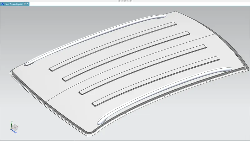
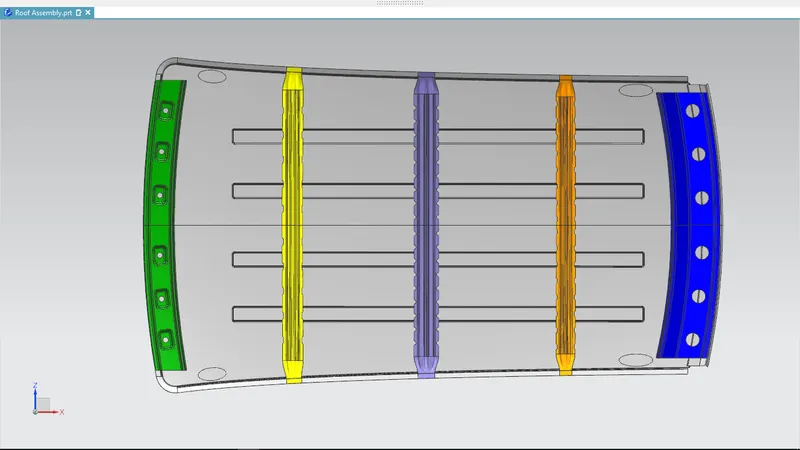
Roof assembly is designed as per the given master section. After designing we should check the design is manufacturability and curvature study on the roof which shows the design is ok or not.
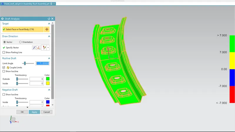
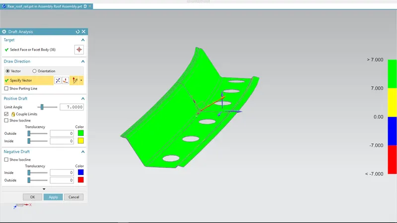
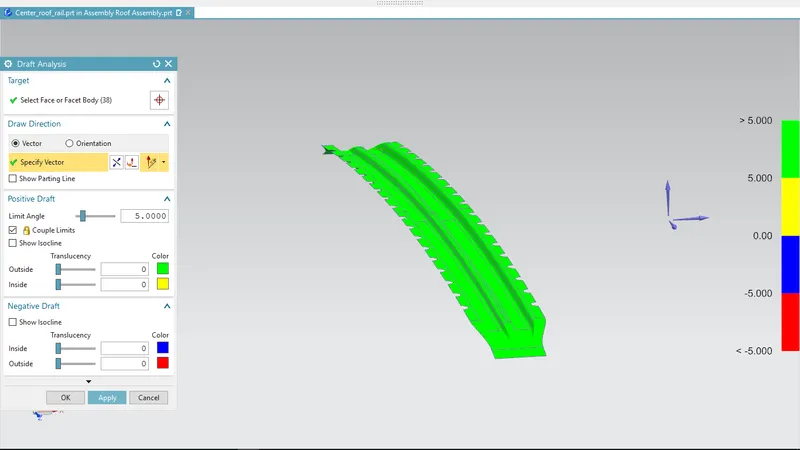
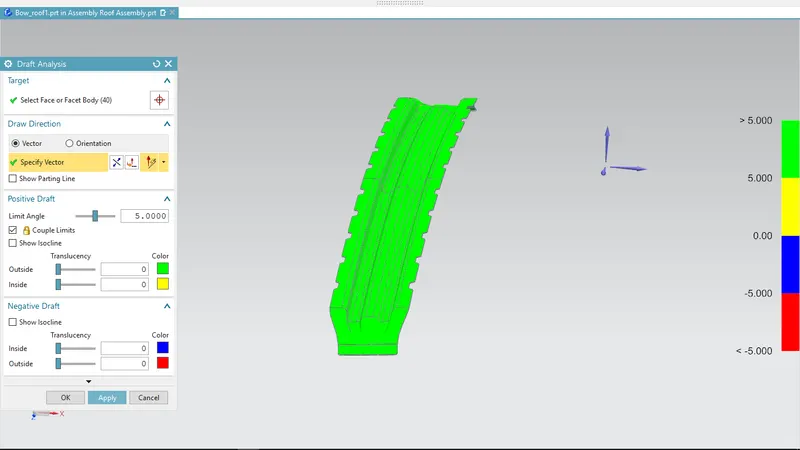
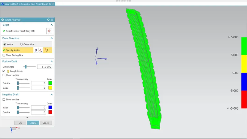
Draft analysis
Front roof rail
Rear roof rail
Centre reinforcement rail
Bow roof 1
Bow roof 2
Bow–Roof Prediction
Heat distortion criteria
Heat distortion temperature is where the metal softens and deforms under a specific load. This study is done to check the ability of the roof to withstand high temperature with respect to the positioning of the reinforcements which contribute to increased strength of the roof.
Formula used
W = [1.73 x 10^(-3) x L] + [1.85 x 10^(-8) x (R^2)/t] + [ 1.10x10^(-3) x l] - 2.68
Where,
L = Roof Length in X-Direction[mm](Roof dimension in 0-Y)
R = Roof curvature
R = 2(Rx*Ry)/(Rx+Ry)
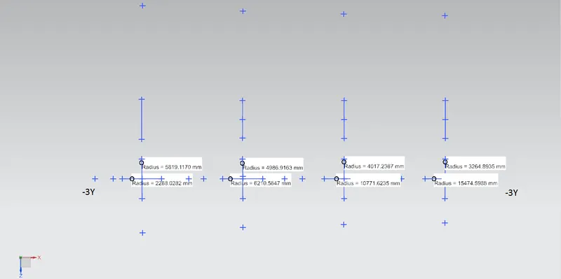
Rx = X curvature
Ry = Y curvature
t = Roof plate thickness [mm]
l = Bow Roof Span [mm]
Judgment Condition
OK< 2.7
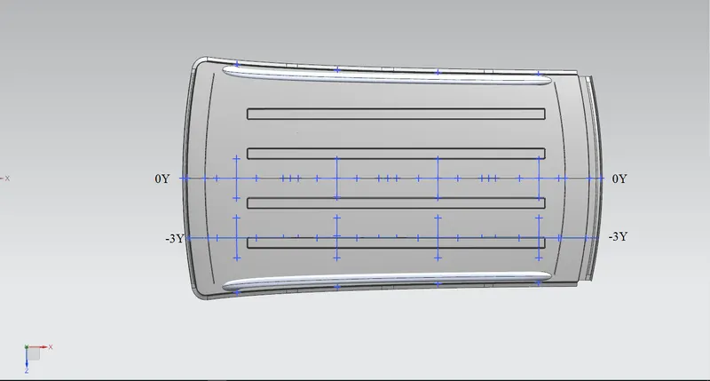
Created sktechs for Heat distrotion calculation:
Tabulation

Snow Load Prediction
Formula used
Qr = [Iy x t2] / [α x s x [(Rx + Ry)/2]2 x 10-8]
Note: The Qr value given over here is correct. There was a typo error in the formula given in the video.
Where,
α = My x Lx2 x 10-12 , My = Y(Ly-Y)
t = Roof plate thickness [mm]
Ly = Distance between the front and rear roof Rails on the Vehicle along with 0Y[mm]
Length of Roof panel with the center point between Roof rail Front /Rear as the front and rear reference point.
Lx = Distance between the Left and Right end of the roof on the Roof BOW [mm]
The width of the roof panel is exposed on the surface.
Y = Distance front Front Roof Rail to Roof BOW[mm]
s = Distance for which Roof BOW bears divided load [mm]
s = L1/2 + L2/2
Iy = Geometrical moment of inertia of Roof BOW (Y cross-section )[mm4]
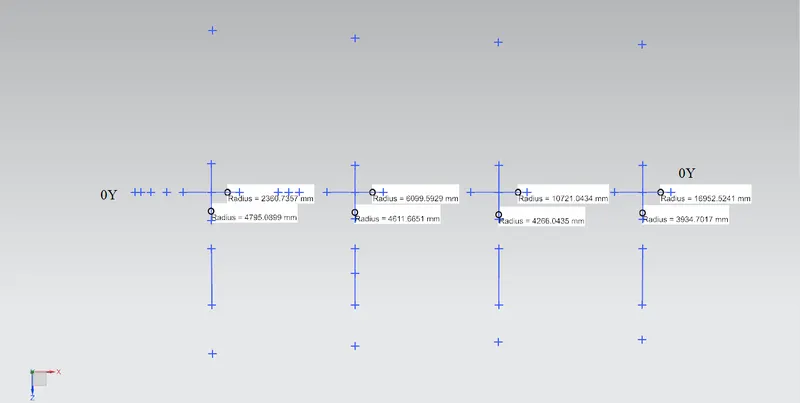
Rx = Lateral direction curvature radius of roof panel Y cross-section on Roof BOW [mm]
Roof panel curvature Radius of the Length Lx in Front view
Ry = Longitudinal Direction curvature radius of the Roof panel X cross-section on Roof BOW [mm]
Roof panel X curvature radius of length s in Side view
Judgment condition
Qr ≥ 3.1
250 ≤ s ≤ 380
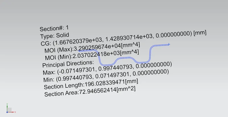
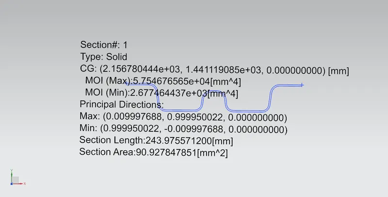
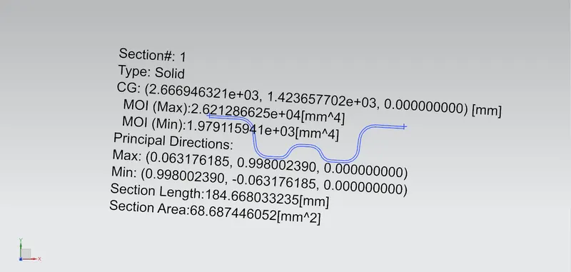
Geometrical moment of inertia of Roof BOW
Bow roof 1
Centre roof rail
Bow roof 2
Created sketches for snow load criteria
Tabulation

Conclusion
The Design of Roof, Front roof rail, Rear Roof Rail, Bow Roofs, and reinforcement roof center are completed by following the Master section and the design parameter. The heat distortion criteria and snow load criteria also calculated and the judgemental condition is OK.