Roof Design
Aim:
To a given roof styling, create essential flanges and reinforcement.
Objective:
- To design the automotive roof based on the given styling surface and to analyze the prepared model to check the manufacturability and the feasibility of the design.
- To perform the section modulus study for the master sections and create for front roof rail, Bow roofs and center roof rail.
- To create the Ditch area and to perform the draft analysis
Introduction:
The car roof, an integral component of automotive design, serves as both a protective covering and an aesthetic element for vehicles. Positioned atop the vehicle's cabin, the roof provides shelter from external elements such as rain, snow, and sunlight, while also contributing to the overall structural integrity and aerodynamics of the vehicle.
Car roofs come in various forms and materials, ranging from traditional steel or aluminum panels to more modern options like panoramic glass roofs or convertible soft tops. Each type offers distinct advantages and characteristics, catering to different consumer preferences and vehicle designs.
Beyond its functional role, the car roof often plays a significant part in the vehicle's design language, influencing its silhouette and contributing to its visual appeal. Sleek, aerodynamic profiles are often sought after to enhance fuel efficiency and performance, while panoramic roofs offer a sense of spaciousness and connection with the surroundings.
Moreover, advancements in technology have led to innovative features such as retractable roofs, allowing drivers to transform their vehicles from enclosed cabins to open-air experiences with the push of a button.
In essence, the car roof represents not only a practical element of automotive engineering but also a canvas for creativity and innovation in design, continually evolving to meet the changing needs and desires of drivers around the world.
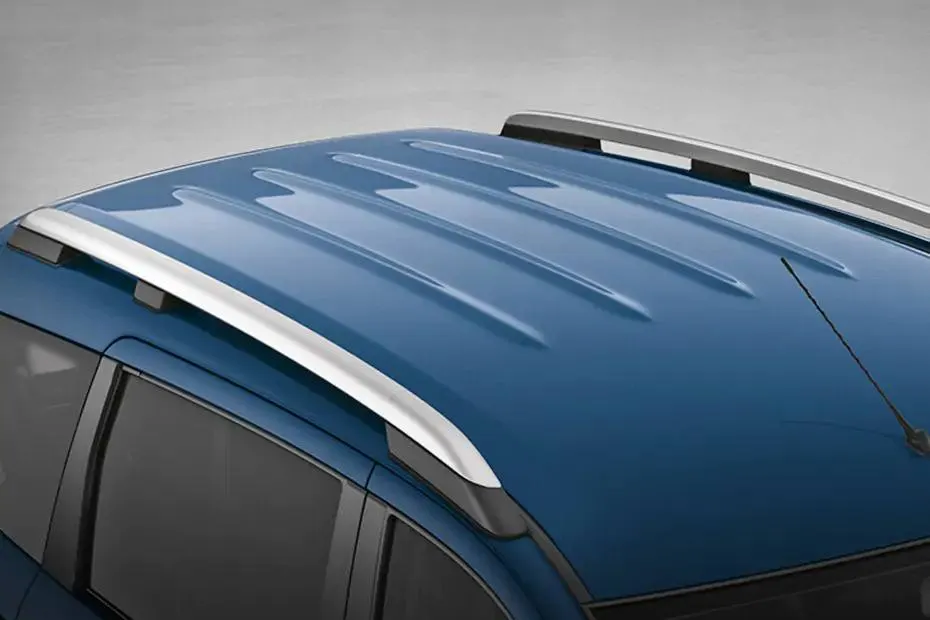
Types of Car Roofs:
1. Convertible roofs.
2. Hard Tops
3. Sun roofs.
4. T- Tops.
5. Target tops.
6. Vinyl roofs.
Design Consideration of roof:
- Visibility Criteria
- Head Clearance
- Curvature Study
- Heat Distortion and snow load criteria
- Draft Analysis
- Safety Parameters
Safety point of view vehicle roof plays a very crucial role especially roll over kind of accidents, In which vehicle tips over onto its side of the roof Vehicle rollover crashes are the cause of many fatalities and head, neck and spine trauma around the world.
Strength of the roof structure to occupant protection in real world roll over crashes, requiring the maximum moving distance of the roof structures should be less than 127 mm, (5 in), where the induced load is 1.5 times the vehicle weight.
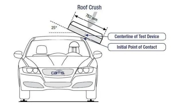
For the test, the passenger ca shall be rigidly placed or positioned on a horizontal surface with the doors locked and the window closed. Furthermore, a flat, rigid block with a lower surface a rectangle measuring 30 inches wide by 72 inches long (762mm x 1829 mm) shall not move more than 5 inches (127mm), measured as the distances between the original location of the lower surface of the test device and its location as the specified force level is reached, when it is used to apply a forces of 1.5 times the unload vehicle weight (UVW) or 5000 lbs. (22224N), whichever is less. To either side or forward edge of the vehicle.
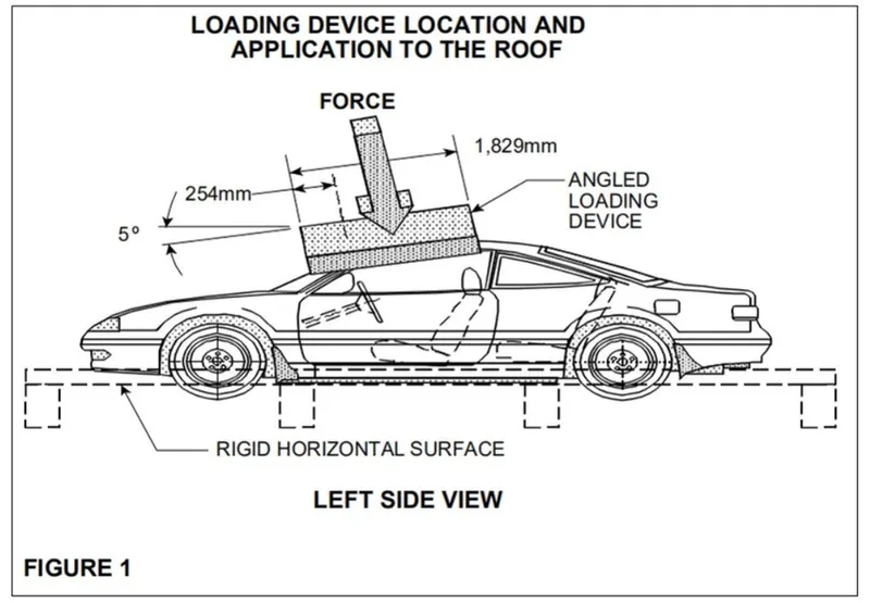
This test can be conducted on either side of the roof structure, the front left or the front right side but not on the both sides in one single test and still meet the requirement of the test. The rigid plate shall not move faster than 0.5 inches/second and the force applied on the plate shall not exceed the lesser of 1.5 times the unloaded vehicle weight (UVW) expressed in kilograms multiplied by 9.8 or 5000 lbs (22240N).
Also, the direction of the force shall be downward and perpendicular to the lower surface of the rigid plate and such that it moves in a straight line without rotation. The duration of the test shall not exceed 120 seconds. The longitudinal axis of the plate is pitched forward at a 5’ angle as viewed from the side of the passenger car as shown,
The lateral axis or the roll of the plate is such that it forms a 25’ outboard angle with a horizontal surface as viewed from the front of the passenger car as shown in below, fig
MASTER SECTION:
FRONT ROOF RAIL:
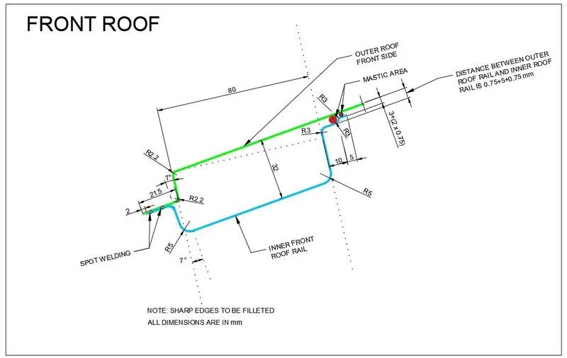
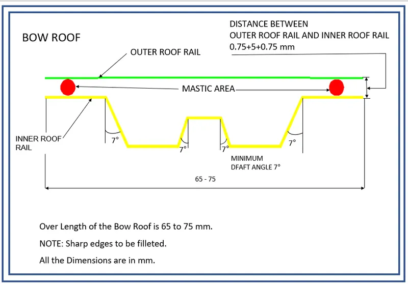
BOW ROOF RAIL:
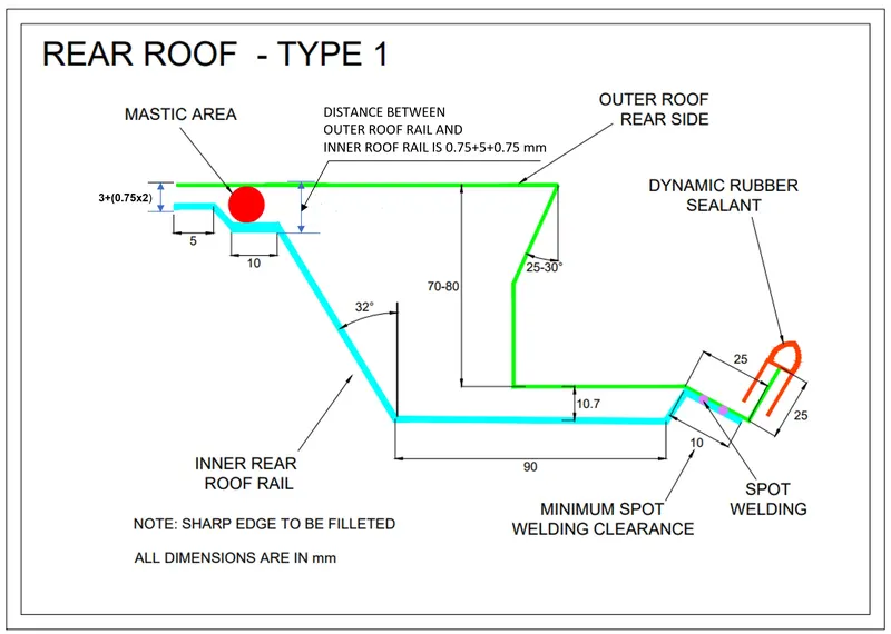
REAR ROOF RAIL:
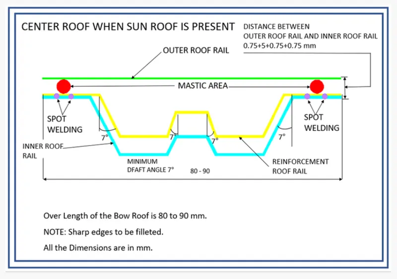
CENTER ROOF WITH SUN ROOF:
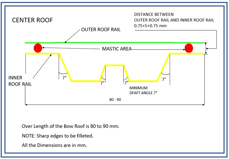
CENTER ROOF WITHOUT SUN ROOF:
Joining Process:
Mastics are introduced between the roof outer panel and the reinforcements for joining. Where ever the mastics are introduced there is remarkable strength. Spot welding is also introduced to join the reinforcement and the outer panel.
Reinforcement and its types:
If the roof is flat, it is weak and cannot able to with stand the external load like snow load, roll over and etc. so in order to increase the strength of the roof, reinforcement like front roof rail, central roof rail, rear roof rail and the bow roof are introduced and joined in the flat surface of the roof with different joining process. In general, there are four types of reinforcement are used in the hard roof top they are,
- Front roof rail
- Central Roof rail
- Rear roof rail
- Bow roof rail
ROOF SKIN DATA (OUTER PANEL):
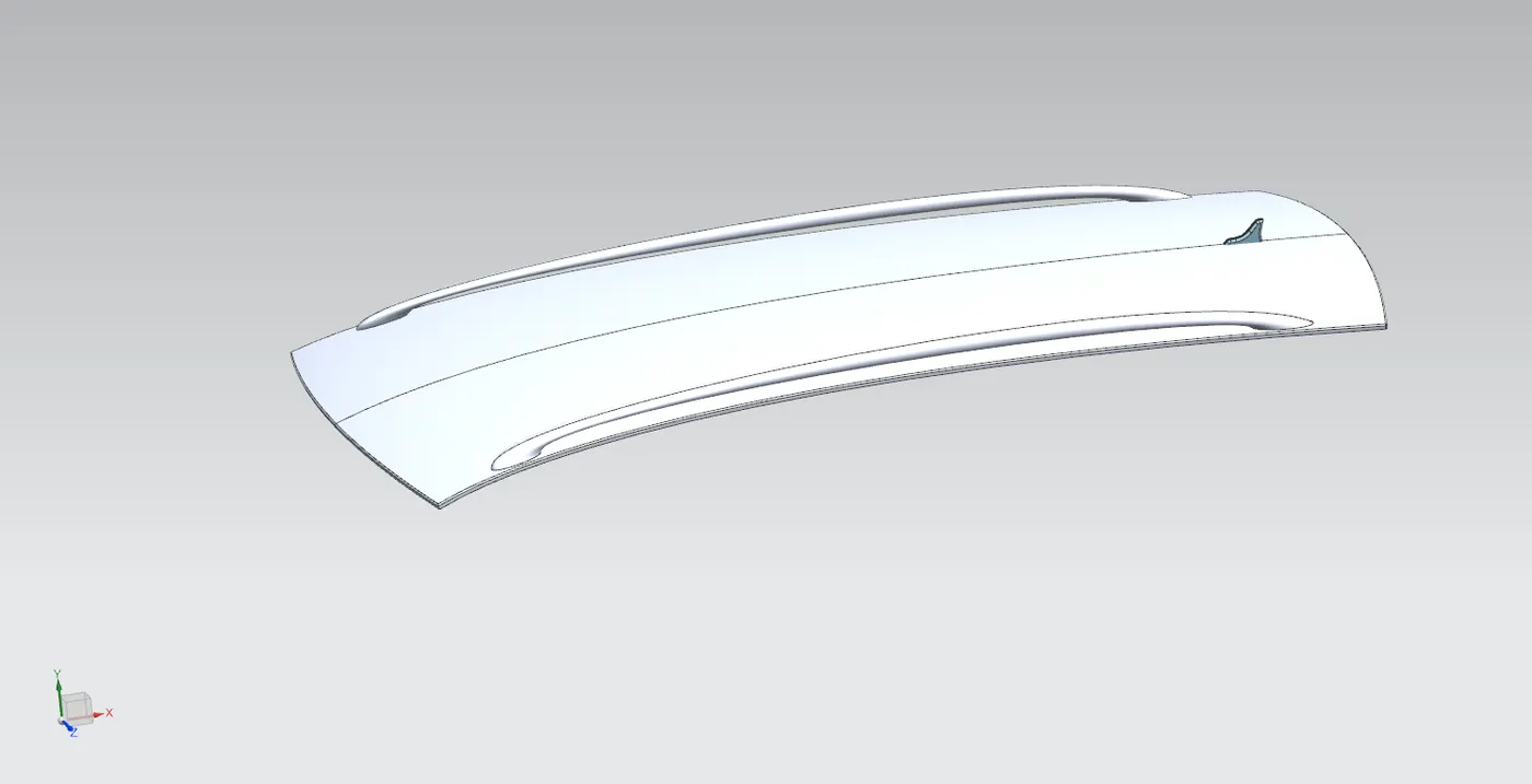
Front roof rail:
Front roof rail is the one which joins the wind shield glass, body side outer and the inner panel also. Here the front roof rail is designed based up on the master section given.
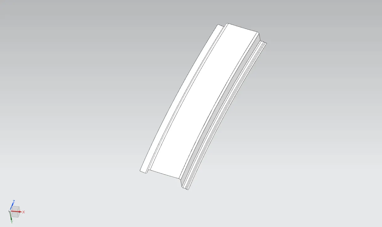
REAR ROOF RAIL:
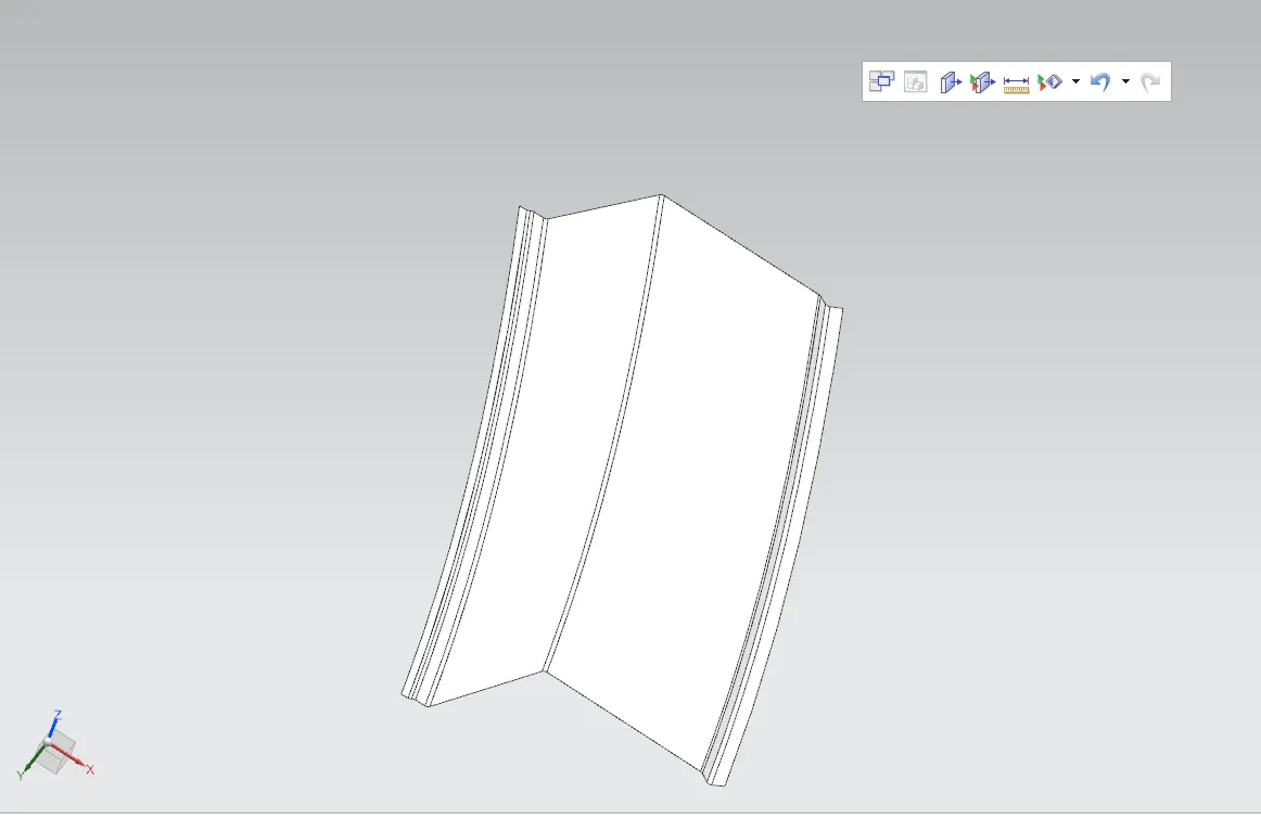
BOW ROOF 1:
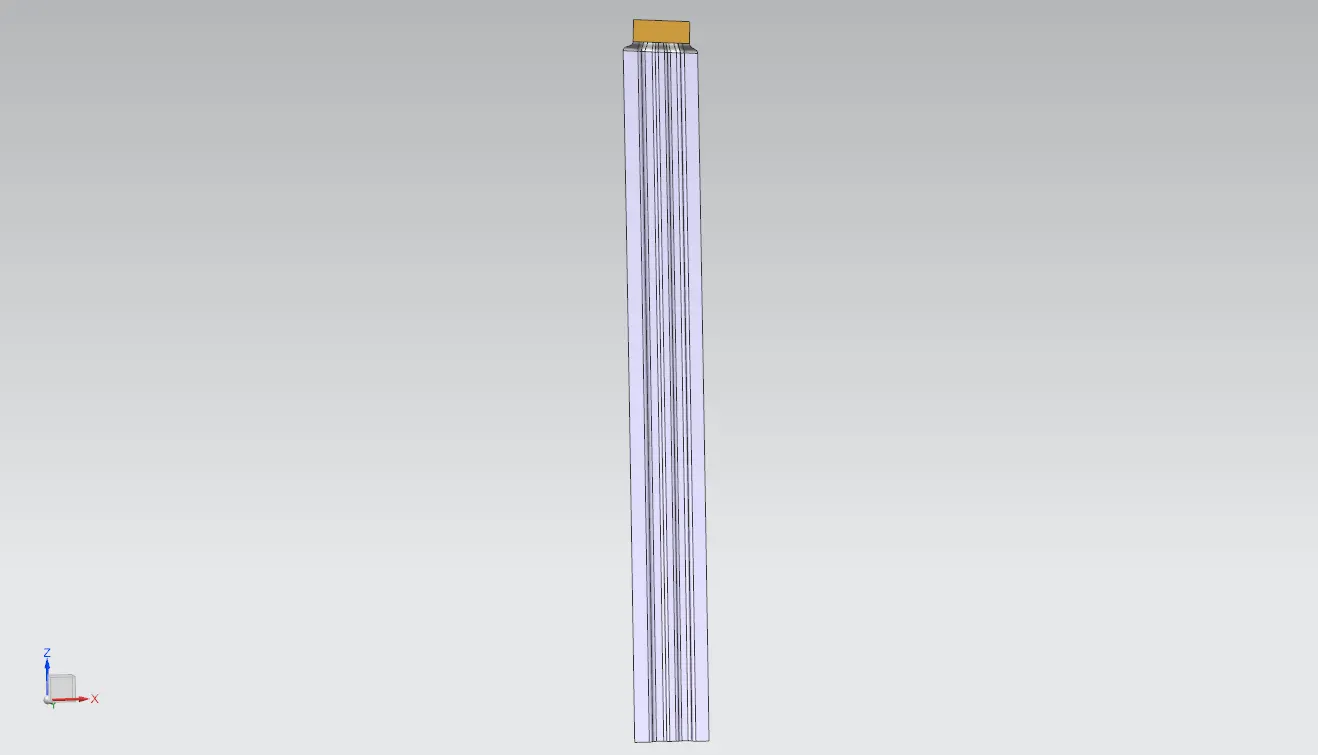
BOW ROOF 2:
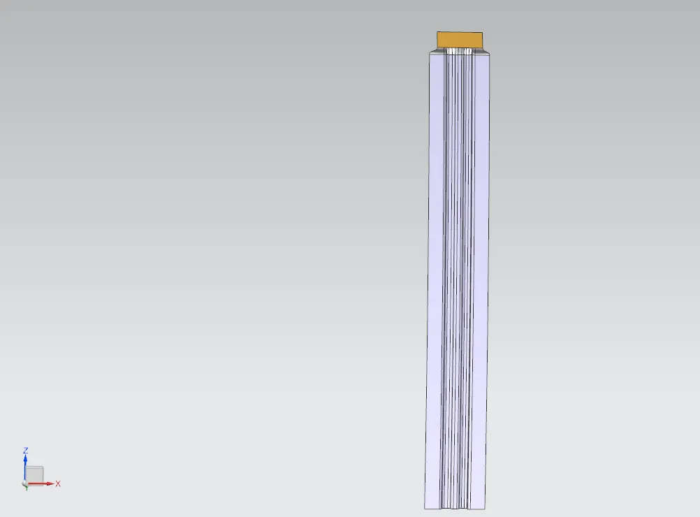
CENTER ROOF DESIGN:
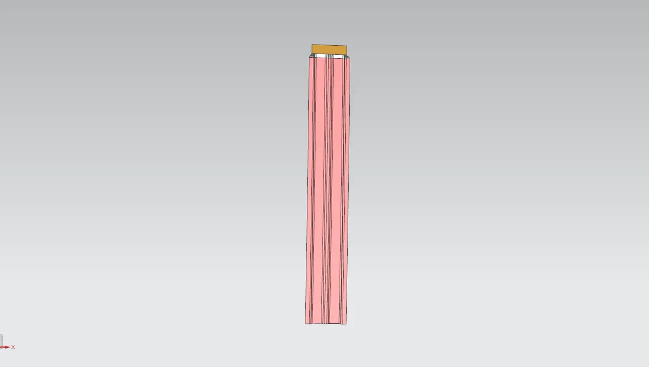
DRAFT ANALYSIS:
In NX to check whether the sheet metal part we have designed can be deep drawn, there is an option called draft analysis. This type of analysis is performed based on color ranges identifying zones on the analyzed element where the deviation from the draft direction at any point, corresponds to specified values.
1. DRAFT ANALYSIS FOR FRONT ROOF:
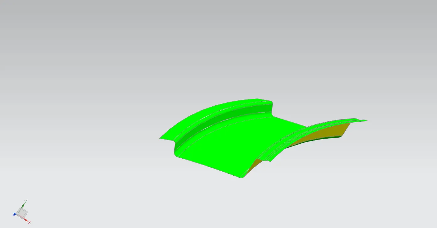
2. DRAFT ANALYSIS FOR BOW ROOF 1:
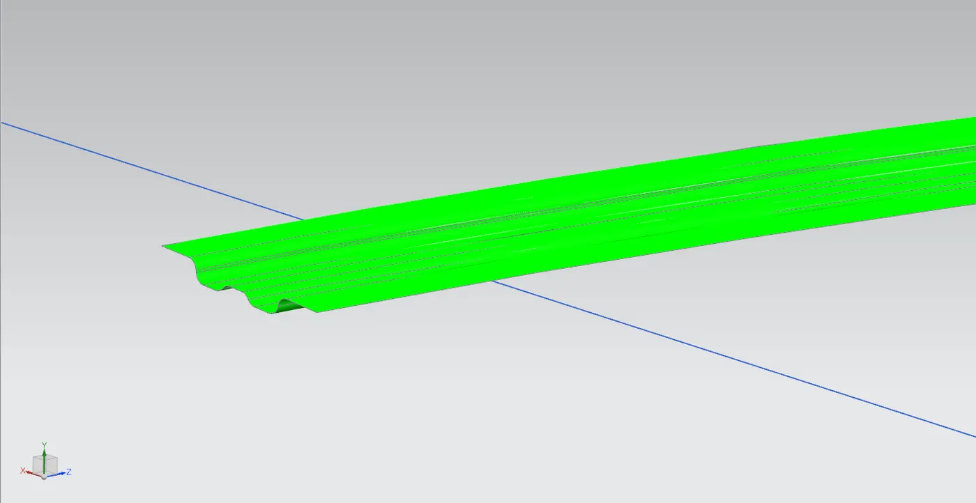
3.DRAFT ANALYSIS FOR BOW ROOF 2:
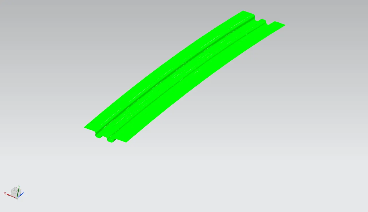
4.DRAFT ANALYSIS CENTER BOW ROOF :
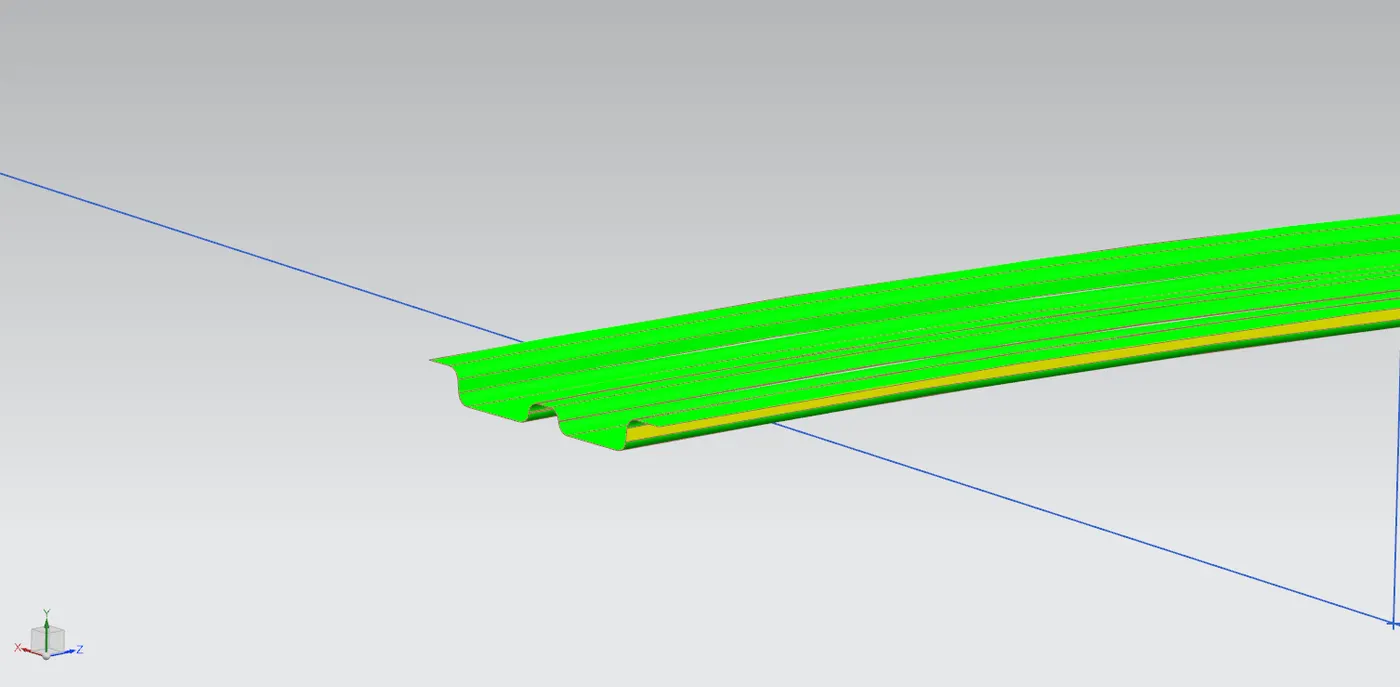
5.DRAFT ANALYSIS REAR BOW ROOF :
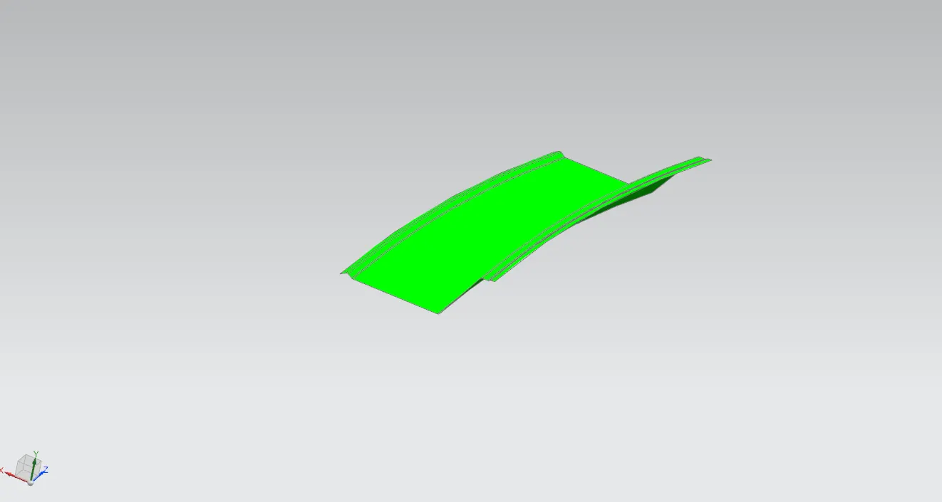
SECTION MODULUS ANALYSIS:
Section modulus analysis is a method used in structural engineering to evaluate the structural strength and stability of various components, such as beams, columns, and shafts. The section modulus (Z) of a structural element is a geometric property that measures its ability to resist bending stresses.
In simple terms, the section modulus is a measure of how far the material in a structural member is distributed from its neutral axis (the axis where there is no bending stress). A larger section modulus indicates that more material is distributed farther from the neutral axis, resulting in greater resistance to bending.
Once the section modulus is calculated, it can be compared to the maximum bending moment the structural member is expected to experience. If the bending moment exceeds the capacity of the member (determined by the section modulus), then failure or deformation may occur.
Section modulus analysis is essential in structural design to ensure that components can withstand the loads they will be subjected to during their intended use. It helps engineers optimize the size and shape of structural elements to achieve the desired strength and stability while minimizing material usage and cost.
1.SECTION MODULUS FOR FRONT ROOF:
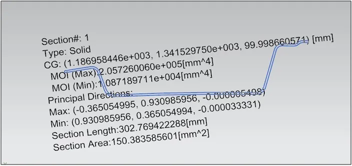
2.SECTION MODULUS FOR BOW ROOF 1:
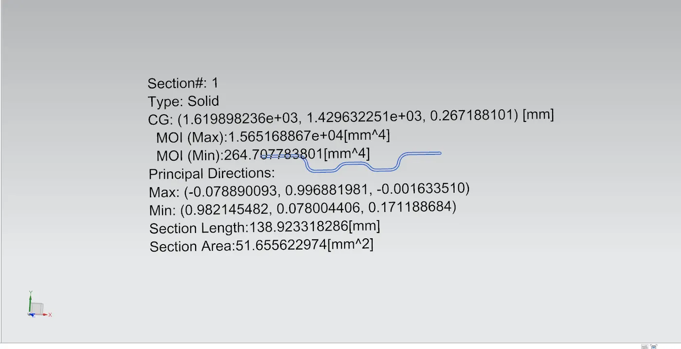
3.SECTION MODULUS FOR BOW ROOF 2:
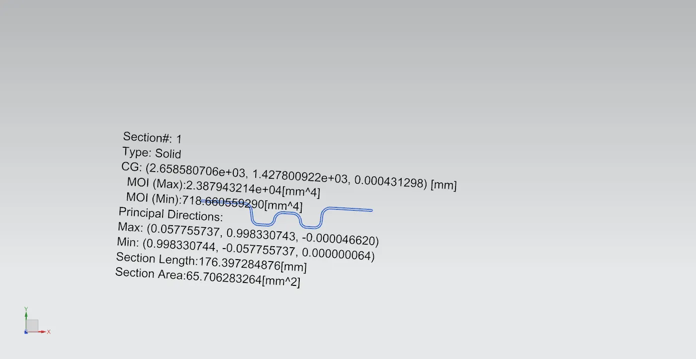
4.SEECTION MODULUS FOR CENTER ROOF:
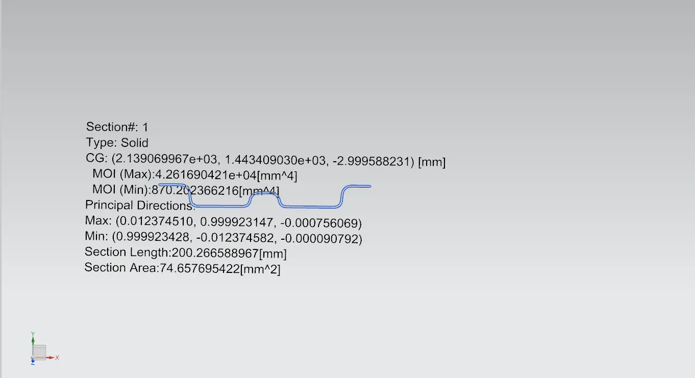
5.SECTION MODULUS FOR REAR ROOF:
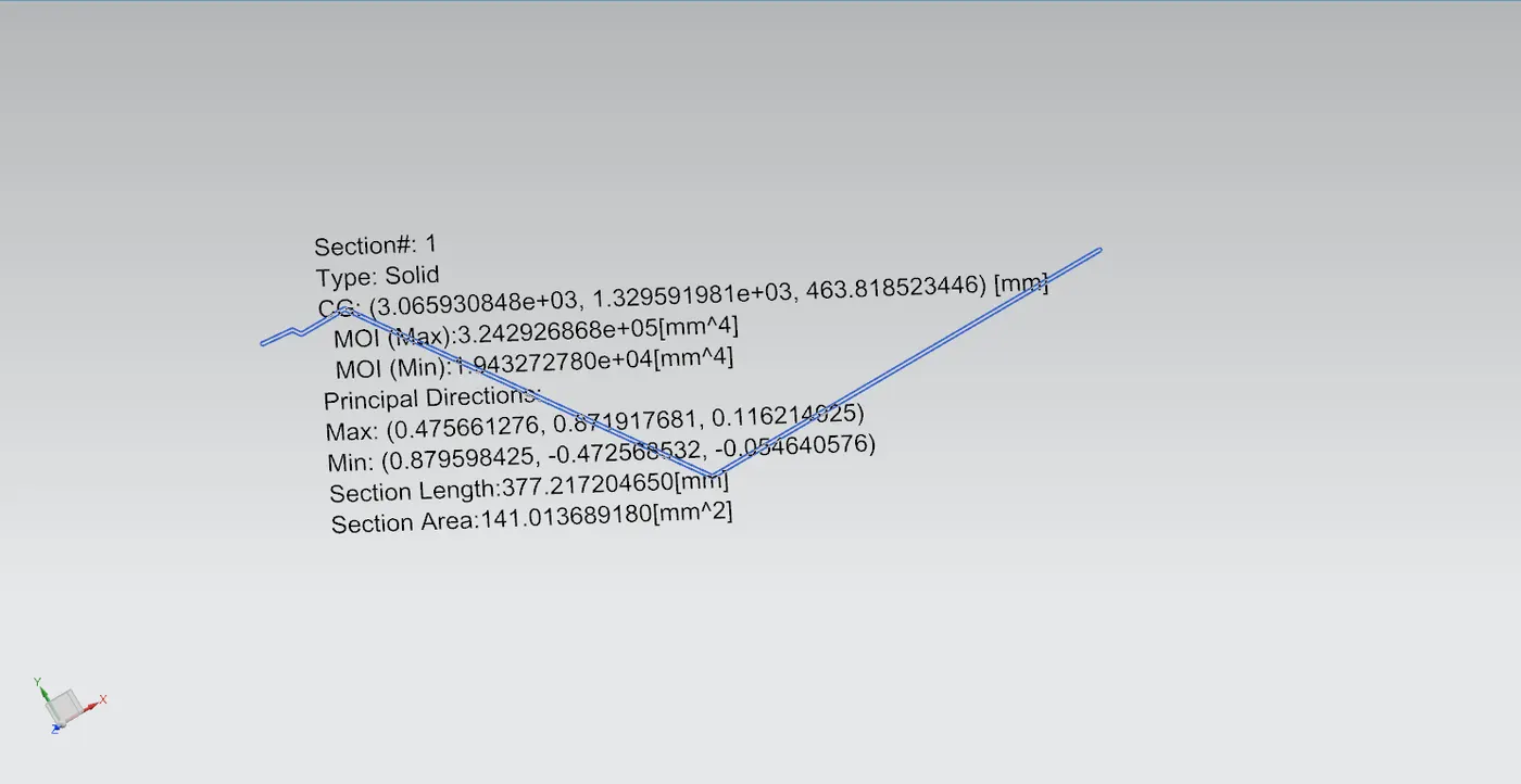
Bow – roof prediction Formula
W = [1.73 x 10^(-3) x L] + [1.85 x 10^(-8) x (R^2)/t] + [ 1.10x10^(-3) x l] - 2.68
Where
L = Roof Length in X-Direction[mm](Roof dimension in 0-Y)
R = Roof curvature
R = 2(Rx*Ry)/(Rx+Ry)
Rx = X curvature
Ry = Y curvature
t = Roof plate thickness [mm]
l = Bow Roof Span [mm]
Judgement Condition : OK< 2.7> 3.1
APPLY THE VALUES IN THE FORMULA :
In order to find the heat distortion apply all the necessary values from the roof to the give formula
CALCULATIONS :

From the above table it can be concluded that all values of w<2.7 and also not w>3.1 so thus infers that current positioning of bow row are good in state as per design and found ok
SNOW LOAD CRITERIA :
This test is done to know how is the roof behaving when there is a snow over . normally due to the snow weight the dent will happen. But the roof should be designed in such a way that when the snow is removal the roof should go it its original position . This is the basic requirements for snow load criteria .
Qr = [Iy x t2] / [α x s x [(Rx + Ry)/2]2 x 10-8]
Where
α = My x Lx2 x 10-12 , My = Y(Ly-Y)
Judgement condition = Qr ≥ 3.1
250 ≤ s ≤ 380
t = Roof plate thickness [mm]
Ly = Distance between the front and rear roof Rails on the Vehicle along with 0Y[mm]
Length of Roof panel with the center point between Roof rail Front /Rear as the reference point of the front and the rear.
Lx = Distance between the Left and Right end of the roof on the Roof BOW [mm]
Width of the roof panel exposed on the surface.
Y = Distance front Front Roof Rail to Roof BOW[mm]
s = Distance for which Roof BOW bears divided load [mm]
s = L1/2 + L2/2
Iy = Geometrical moment of inertia of Roof BOW (Y cross-section )[mm4]
Rx = Lateral direction curvature radius of roof panel Y cross-section on Roof BOW [mm]
Roof panel curvature Radius of the Length Lx in Front view
Ry = Longitudinal Direction curvature radius of the Roof panel X cross-section on Roof BOW [mm]
APPLY THE VALUES IN THE FORMULA :
In order to find the snow load criteria apply all the necessary values from the roof to the give formula
It is observed from the values that obtained values of QR > 3.1
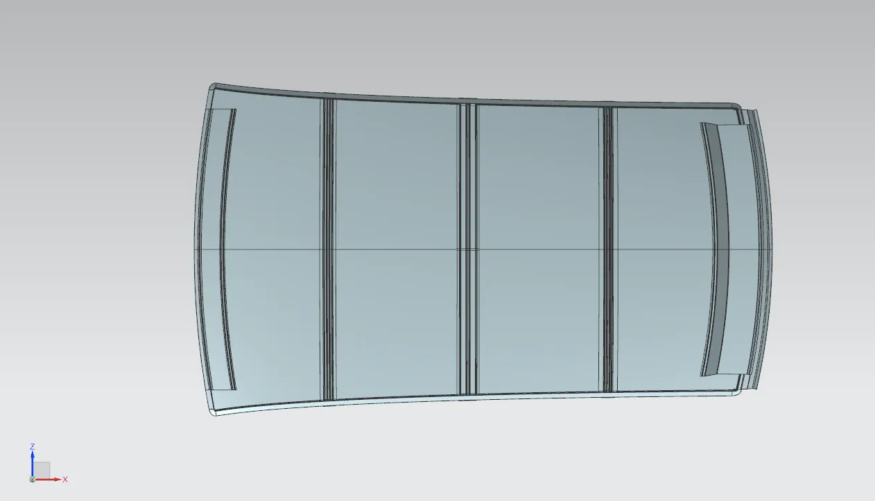
FRONT VIEW:
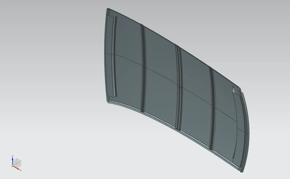
ISOMETRIC VIEW:
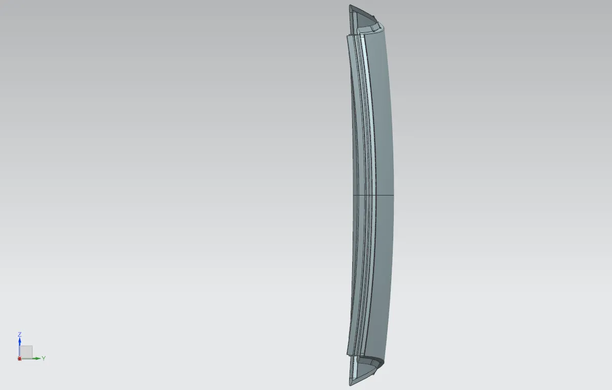
SIDE VIEW:
CONCLUSION:
Hence the roof , front roof rail, bow roof rails , central roof rail and the rear roof rail is designed by following the master sections and the moment of inertia and draft analysis are carried out to check feasibility manufacturing.