Roof Design
Roof design Challange
Objective: The aim of this project is to develop essential flanges and reinforcement for a specified roof styling in the automotive industry.
Project Objectives:
- Design the automotive roof according to the provided styling surface.
- Analyze the prepared model to assess manufacturability and design feasibility.
- Conduct a section modulus study for master sections, including front roof rail, bow roofs, and center roof rail.
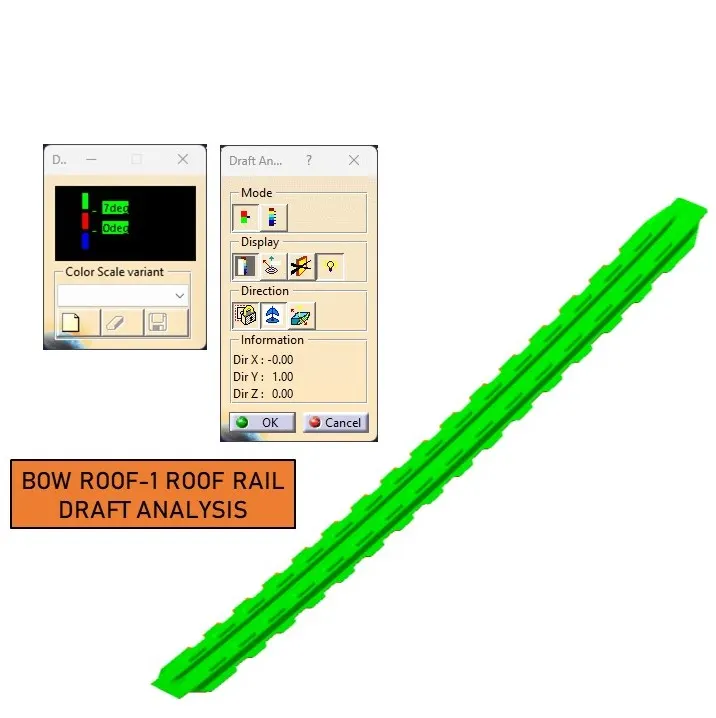
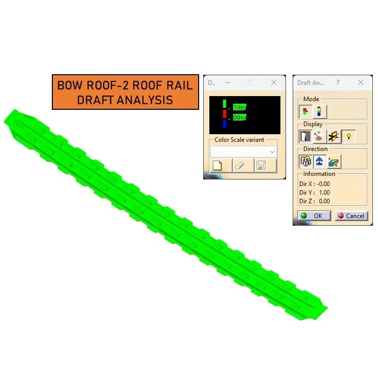
- Create the Ditch area and perform draft analysis.
Introduction to Automotive Roofs:
An automotive roof, also known as a car top, is the upper part of a vehicle that covers the passenger compartment, shielding occupants from external elements like sunlight, wind, and rain.
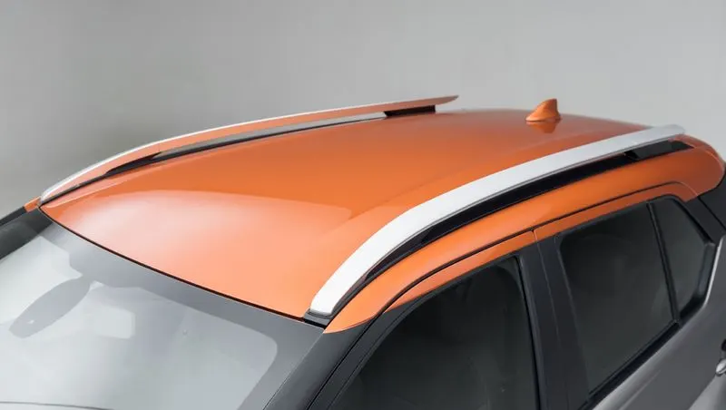
Underneath the exterior styling surfaces, various reinforcement structures enhance the roof's strength and stability. These include the Front Roof Rail, Rear Roof Rail, Center Rail, and Bow Roof Design. These components, mastics, and spot welding on the roof flanges contribute to the roof's strength and improve noise,vibration, and harshness (NVH) values.
Types of Car Roofs:
1.Convertible roofs
2.Hard Tops
3.Sunroofs
4.T-Tops
5.Target tops
6.Vinyl roofs
Design Considerations:
- Visibility criteria
- Head clearance
- Curvature study
- Heat distortion and snow load criteria
- Draft analysis
- Safety parameters
Roof Crush Test for Passenger Cars:
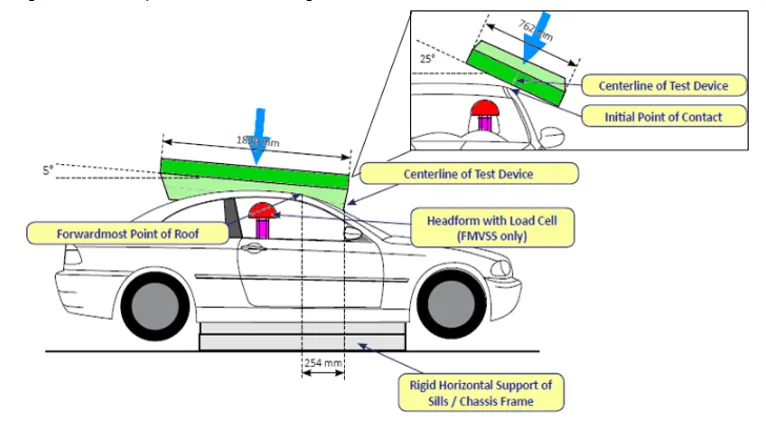
The strength of the vehicle roof is crucial in rollover accidents, with rollover crashes being a leading cause of fatalities worldwide. Standards dictate that in such accidents, the maximum roof displacement should be less than 127 mm under a load 1.5 times the vehicle weight.
1.Preparation for the Test:
- The passenger car must be rigidly positioned on a horizontal surface with its doors locked and windows closed.
- A flat, rigid block with specific dimensions (30 inches wide by 72 inches long) is used in the test.
2.Movement Limitations:
- During the test, the rigid block should not move more than 5 inches (127 mm) from its original position.
- This movement is measured as the distance between the original location of the lower surface of the block and its location when the specified force level is reached.
- The force applied during the test should be either 1.5 times the unloaded vehicle weight (UVW) or 5000 lbs. (22224N), whichever is less.
3. Test Procedure: - The test can be conducted on either the front left or front right side of the roof structure, but not on both sides simultaneously.
- The rigid plate should not move faster than 0.5 inches/second during the test.
- The force applied on the plate should not exceed 1.5 times the unloaded vehicle weight (UVW) multiplied by 9.8 or 5000 lbs (22240N).
- The direction of the force should be downward and perpendicular to the lower surface of the rigid plate.
- The force should move in a straight line without rotation.
- The duration of the test should not exceed 120 seconds.
4. Orientation of the Plate:
- The longitudinal axis of the plate is pitched forward at a 5-degree angle when viewed from the side of the passenger car.
- The lateral axis or the roll of the plate forms a 25-degree outboard angle with a horizontal surface when viewed from the front of the passenger car.
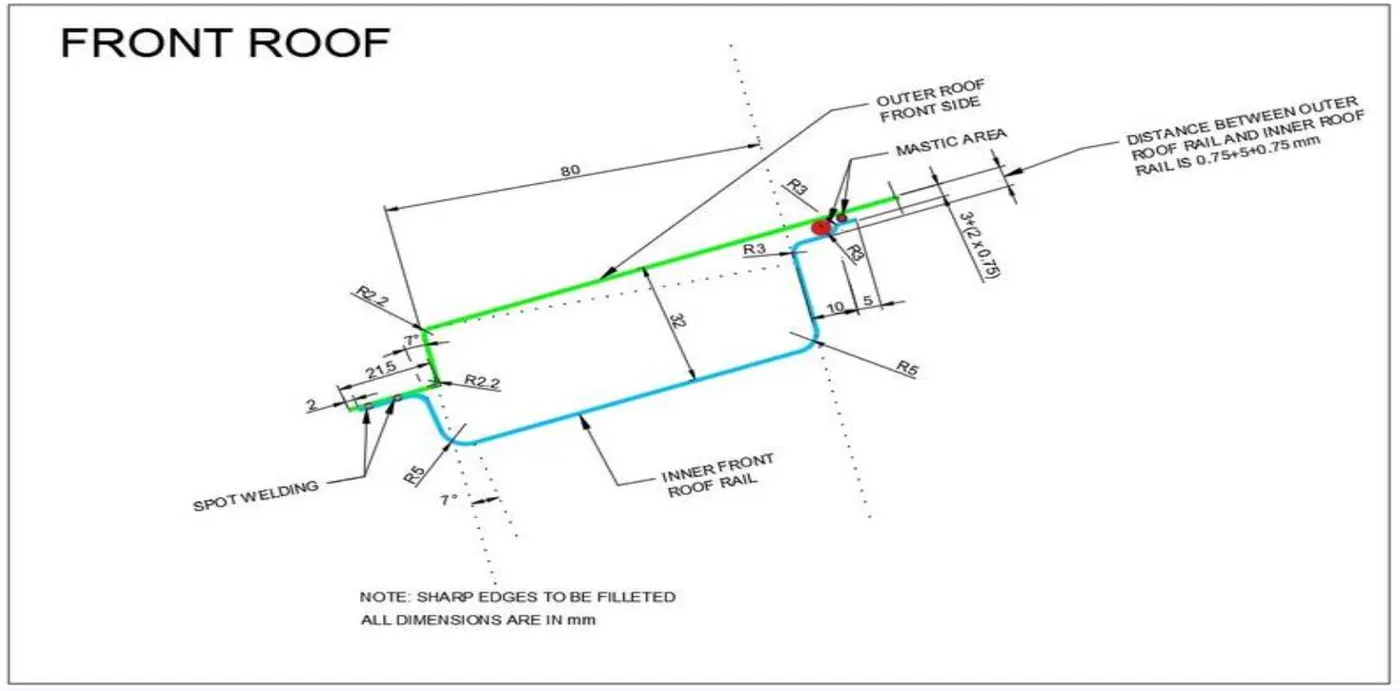
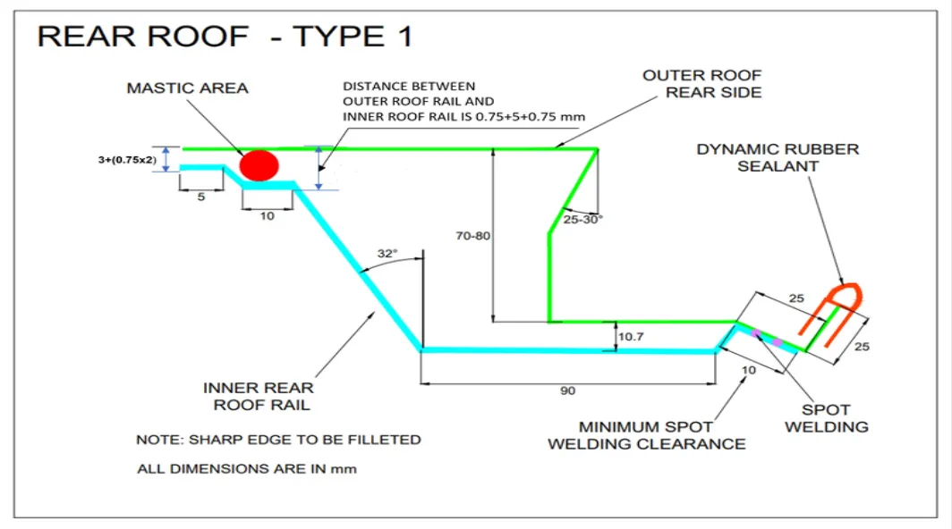
Master Section and Its Parameters:
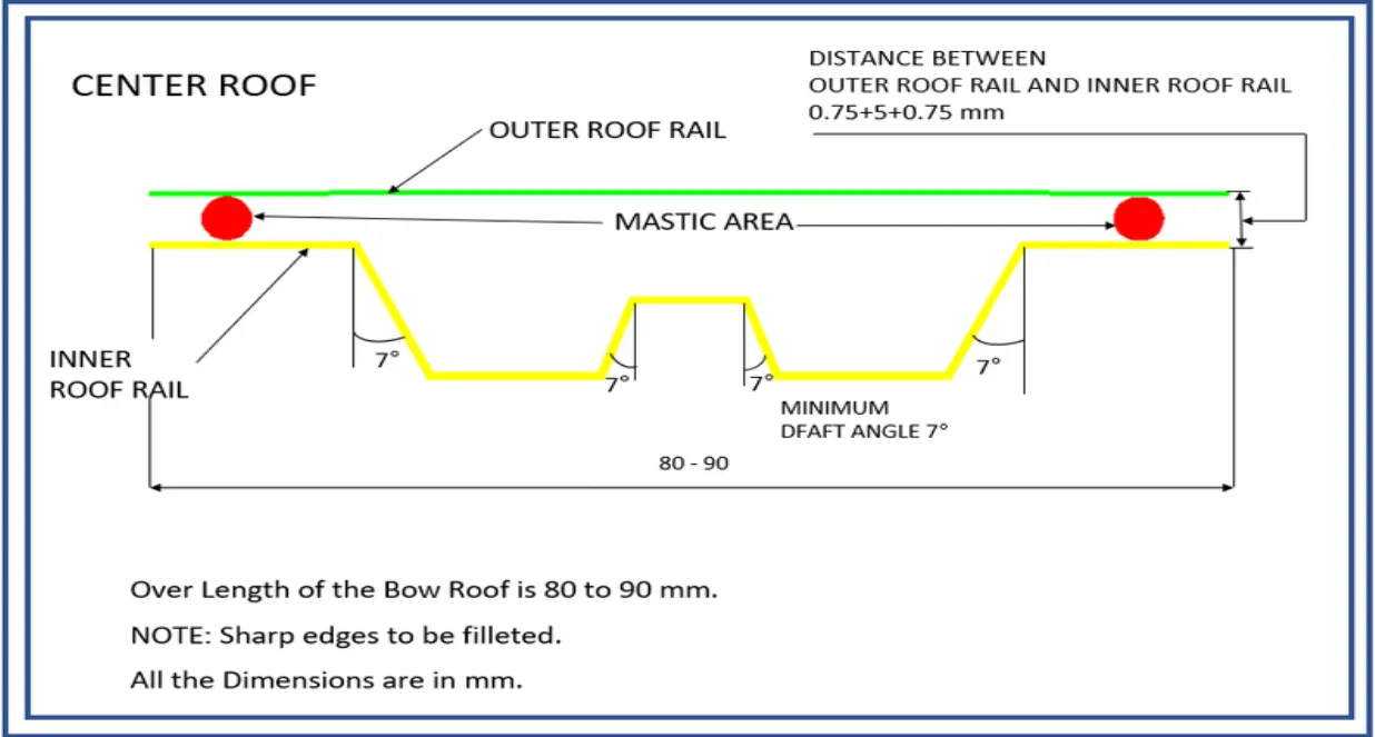
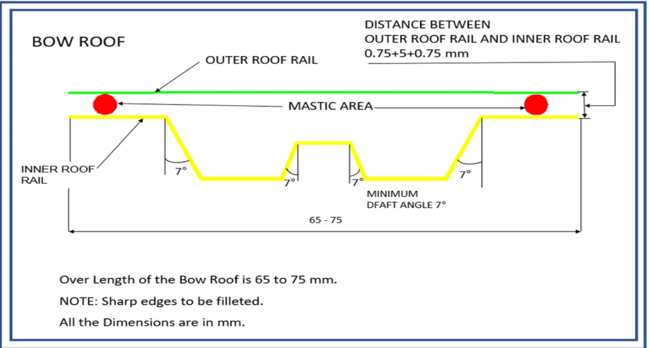
Joining Process:
Mastics and spot welding are used to join the reinforcement and outer panels, enhancing structural strength.
Reinforcement Types:
Various reinforcements like front, central, rear roof rails, and bow roofs are introduced to enhance the roof's load-bearing capacity.
Roof Outer Panel:
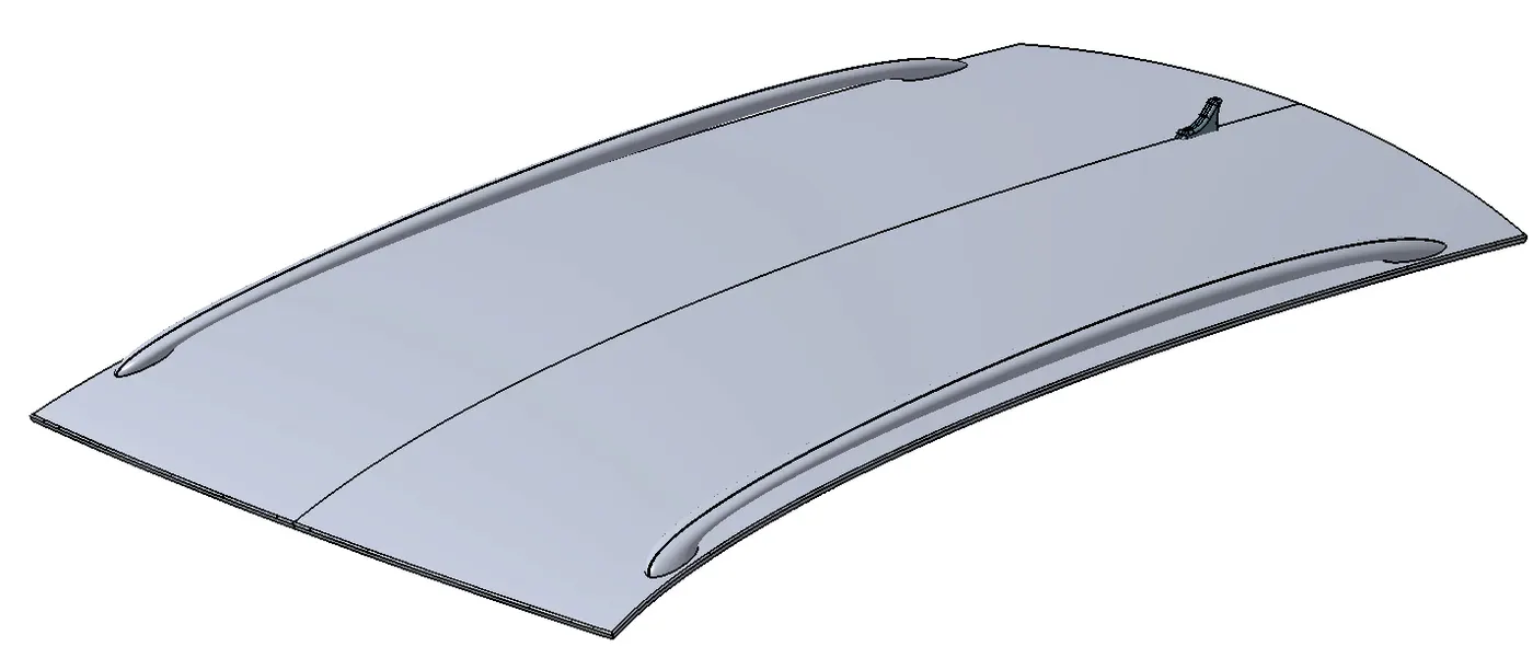
The outer panel of the roof is crucial for structural integrity and aesthetics.
Front Roof Rail:
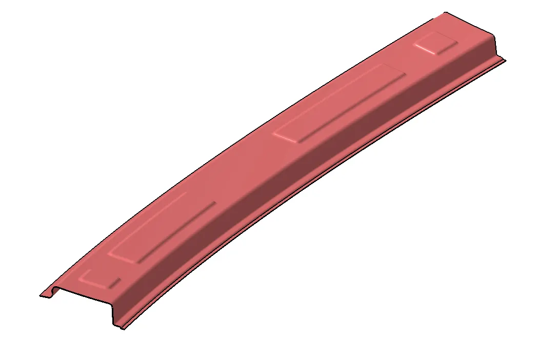
The front roof rail joins the windshield glass, body side outer and inner panels.
Rear Roof Rail:
Similar to the front rail, the rear rail reinforces the rear part of the car roof.
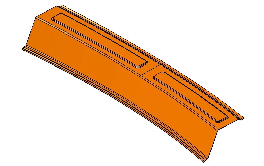
Central Roof Rail:
The central roof rail provides support to the flat area of the roof, improving its strength during rollover tests.
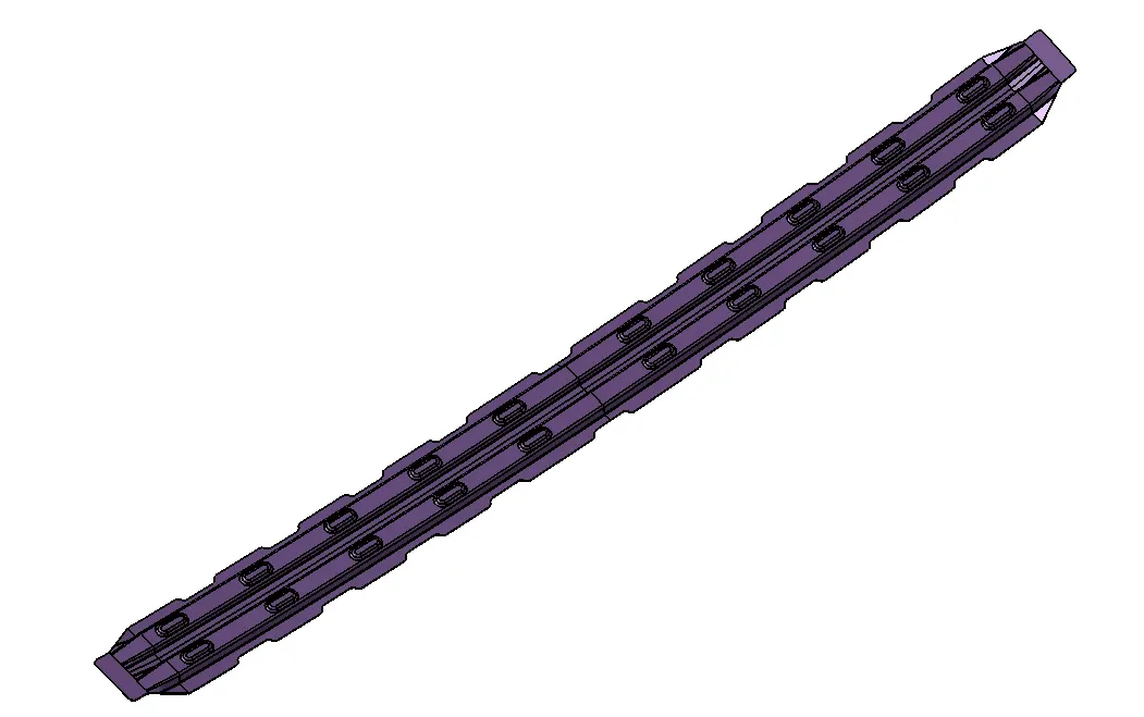
Bow Roof:
Bow roofs improve torsional stiffness and load-bearing capacity, with their number depending on the roof's size.
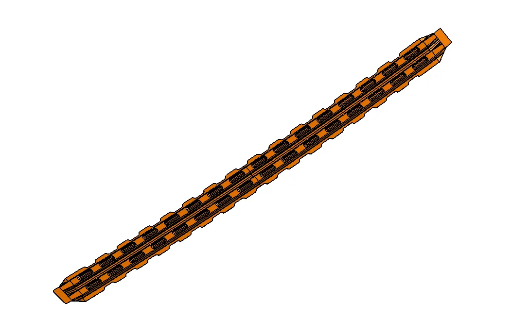
Panel with Roof Assembly:
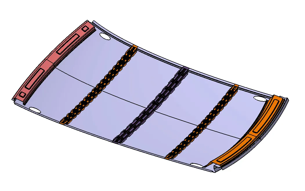
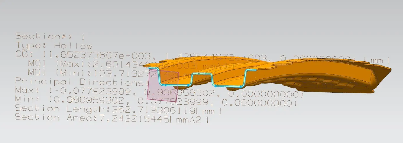
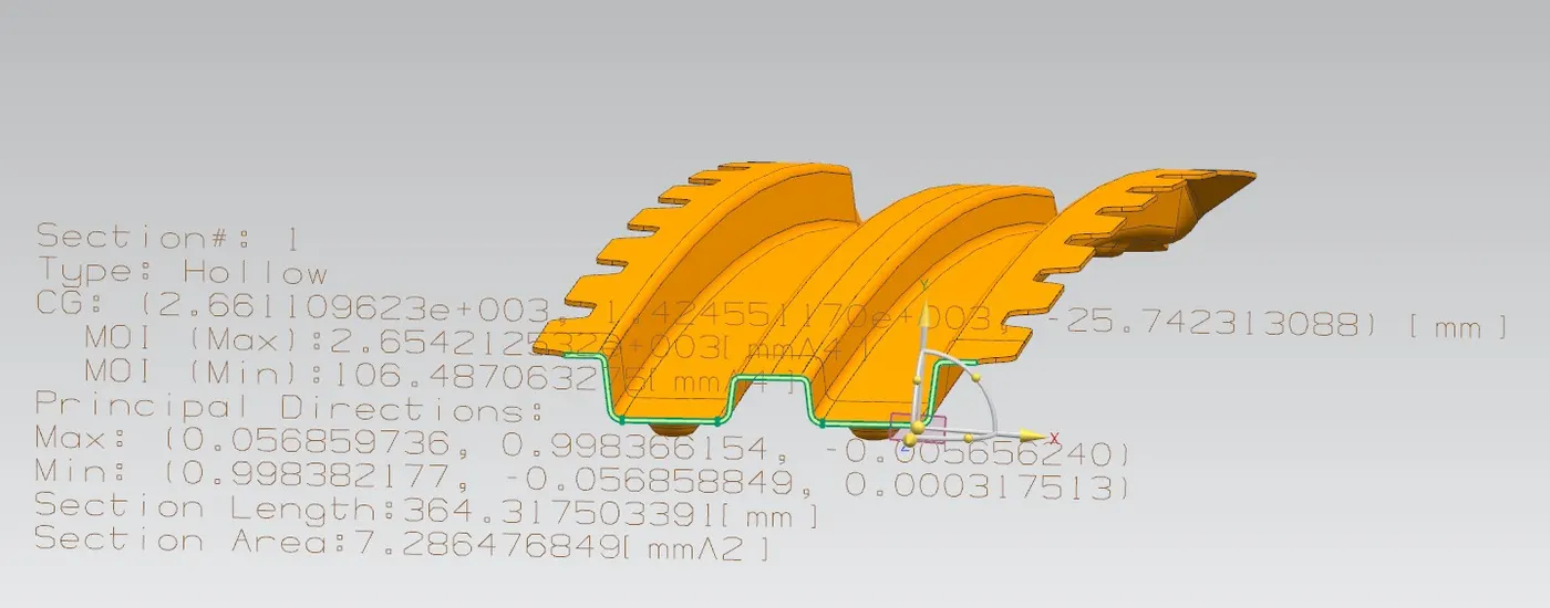
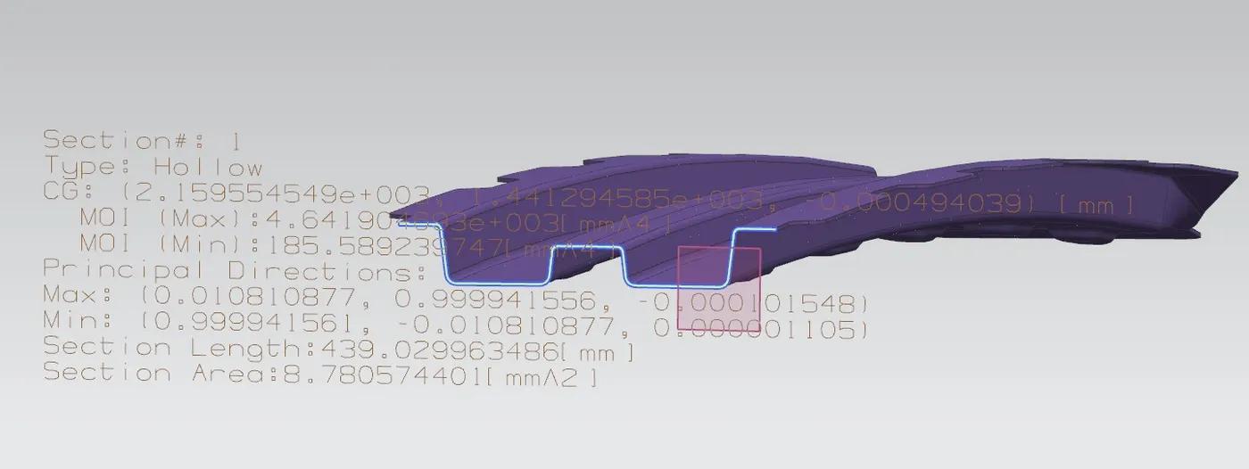
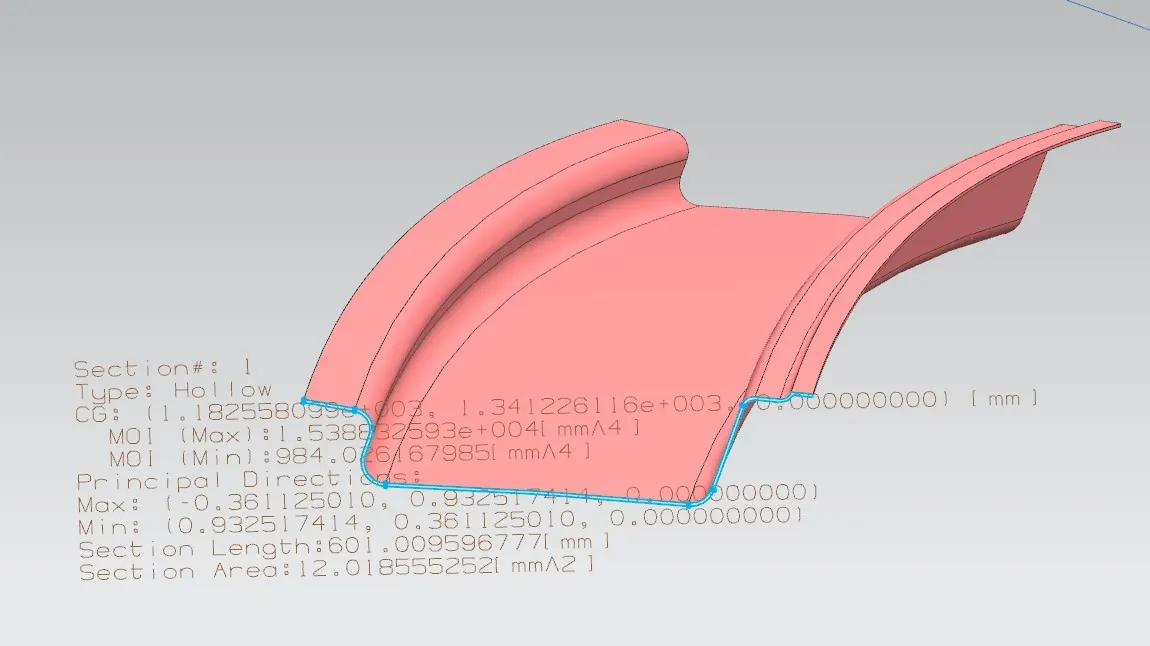
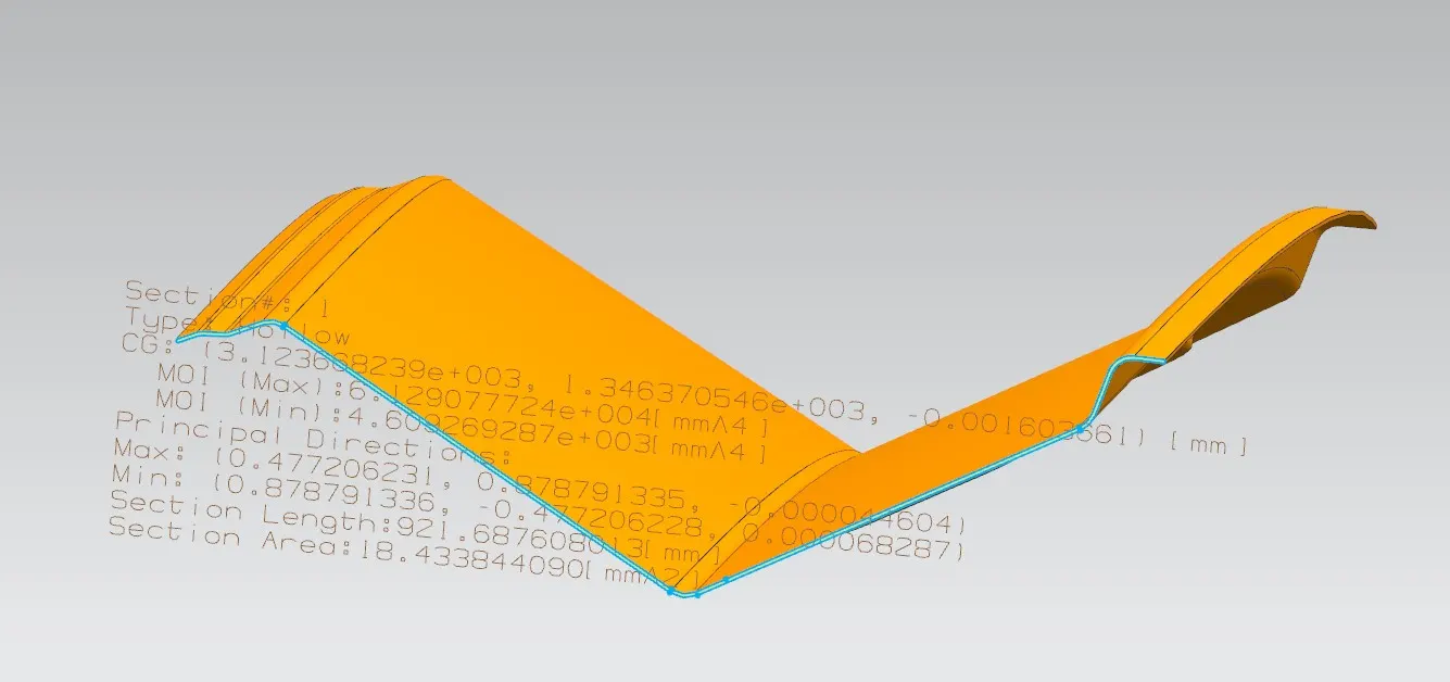
Section inertial Analysis of Bow roofs [CatPart to .prt conversion to analyze in NX]
Bow Roof 1:
Bow Roof 2:
Center Roof:
Front roof rail:
Rear roof rail:
Design Calculation of Roof:
Design considerations include heated distortion and snow load conditions to ensure structural integrity under various conditions.
Heated Distortion [Bow–Roof Prediction Formula]
W = [1.73 x 10^(-3) x L] + [1.85 x 10^(-8) x (R^2)/t] + [ 1.10x10^(-3) x l] - 2.68
Where,
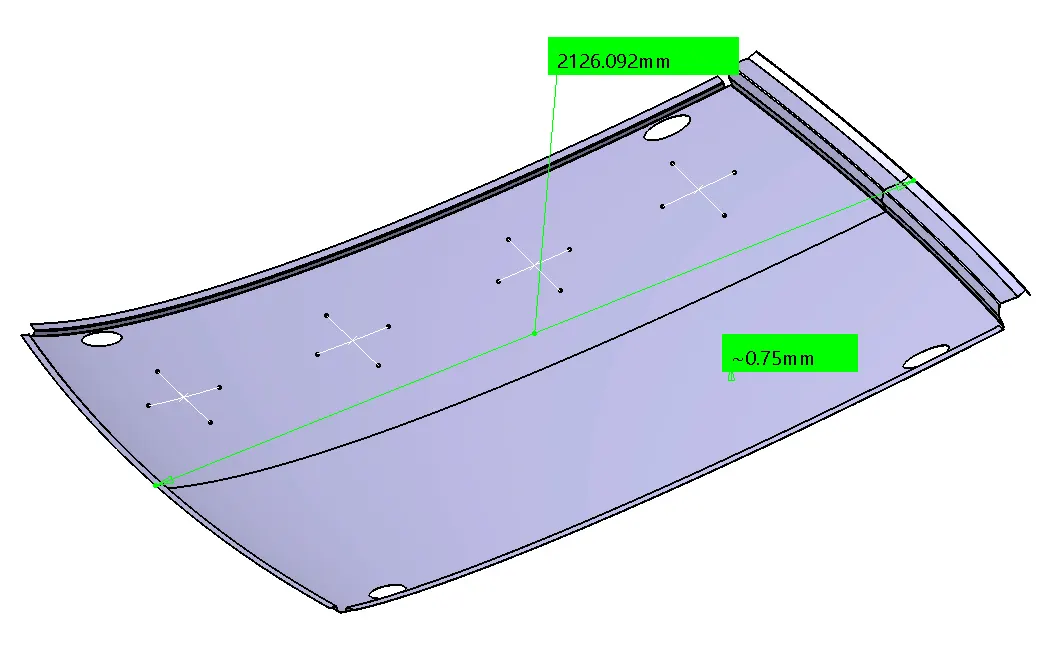
L = Roof Length in X-Direction[mm](Roof dimension in 0-Y)
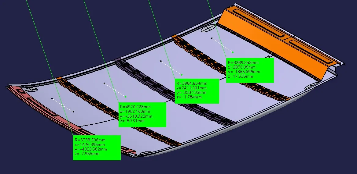
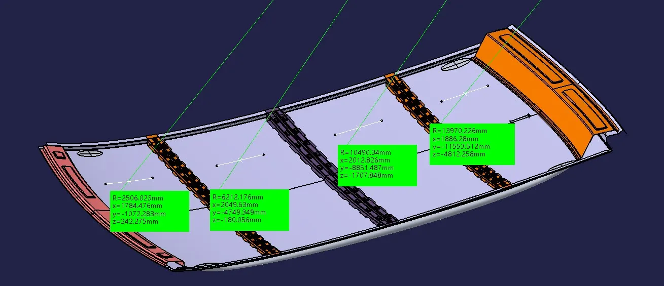
R = Roof curvature
R = 2(Rx*Ry)/(Rx+Ry)
Rx = X curvature
Ry = Y curvature
t = Roof plate thickness [mm]
l = Bow Roof Span [mm]
Judgment Condition
OK< 2.7
For Rx Values:
For Ry Values:
For L & t Values:

Snow Load Prediction Formula
Qr = [Iy x t2] / [α x s x [(Rx + Ry)/2]2 x 10-8]
Note: The Qr value given over here is correct. There was a typo error in the formula given in the video.
Where,
α = My x Lx2 x 10-12 , My = Y(Ly-Y)
t = Roof plate thickness [mm]
Ly = Distance between the front and rear roof Rails on the Vehicle along with 0Y[mm]
Length of Roof panel with the center point between Roof rail Front /Rear as the front and rear reference point.
Lx = Distance between the Left and Right end of the roof on the Roof BOW [mm]
The width of the roof panel is exposed on the surface.
Y = Distance front Front Roof Rail to Roof BOW[mm]
s = Distance for which Roof BOW bears divided load [mm]
s = L1/2 + L2/2
Iy = Geometrical moment of inertia of Roof BOW (Y cross-section )[mm4]
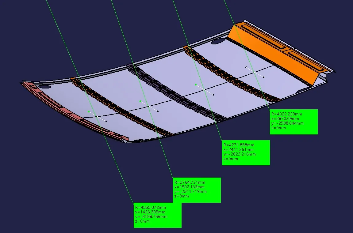
Rx = Lateral direction curvature radius of roof panel Y cross-section on Roof BOW [mm]
Roof panel curvature Radius of the Length Lx in Front view
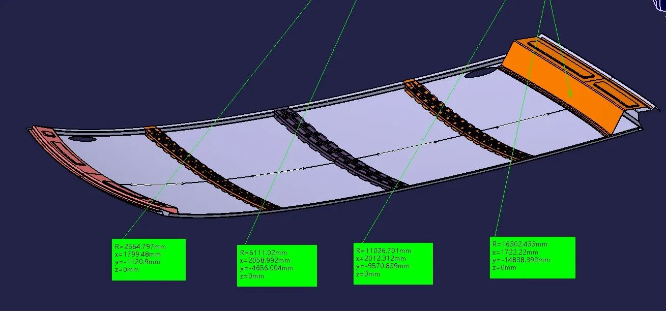
Ry = Longitudinal Direction curvature radius of the Roof panel X cross-section on Roof BOW [mm]
Roof panel X curvature radius of length s in Side view
Judgment condition
Qr ≥ 3.1
250 ≤ s ≤ 380
For Rx Values:
For Ry Values:

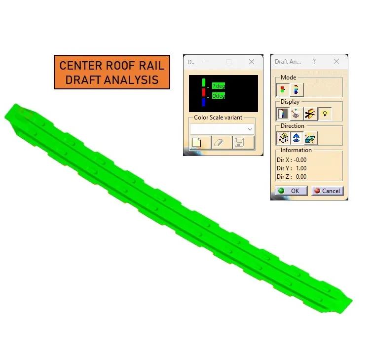
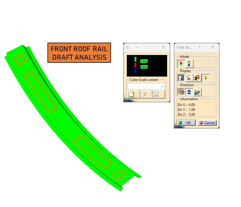
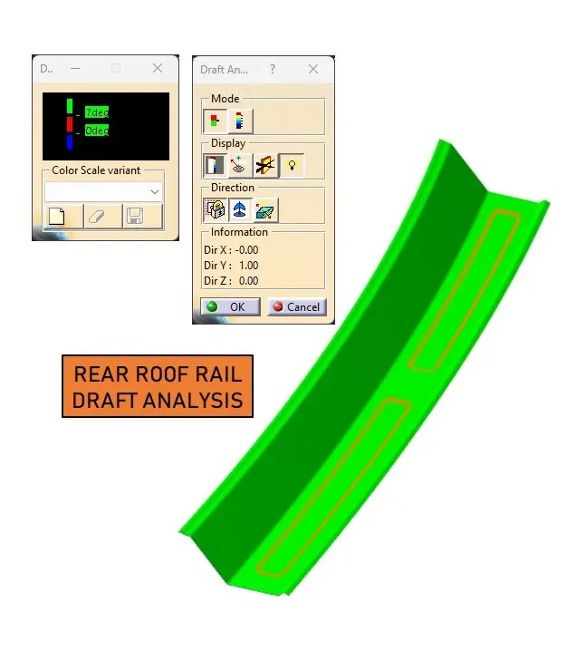
Draft Analysis:
Draft analysis determines if a part can be easily removed, crucial for manufacturing.
Conclusion:
The project successfully designed and developed the required reinforcements and ditch areas for the roof based on the provided styling. Curvature, section modulus, and draft analysis were conducted to ensure structural integrity and manufacturability.