Roof Design
Objective:For the given roof styling create an assembly by developing the essential flanges for outer roof and creating the reinforcements.
Provide appropriate dimensions and check for Draft analysis.
Do a curvature study on the roof and perform calculations to determine the position of the bow roofs.
Introduction:
An automobiles roof or car top is the portion of an automobiles that sits above the passenger compartment,protecting the vehicle occupants from sun,wind,rain,and other external elements,Because the earliest automobiles were designed in an era of horse-drawn carriages,early auomobiles roofs used similar materials and designs.
Different type of roofs:
- Convertable roofs
- Roof modules
- Hardtops
- Sunroofs
- T tops
- Targa tops
- Vinyl roofs
Commenly the roofs have reinforments to provide strength to the overall strecture and withstand the overhead forces like snow or roll over etc.
Types of Reinforcements:
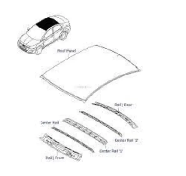
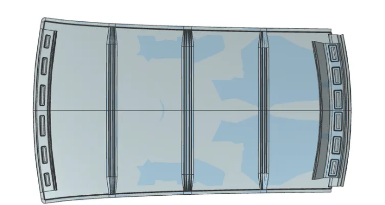
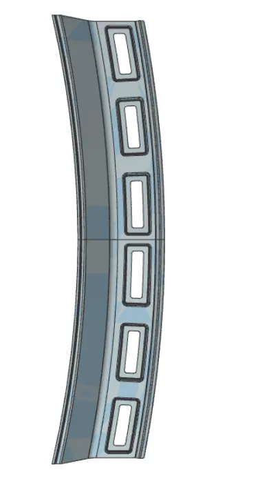
Front roof:The one which joins the windshield glass,body side outer and the inner panel.
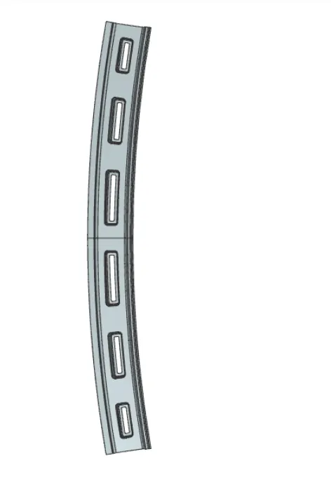

Rear roof rail:It helps in joining the rear door,the design of the rear roof rail differs by the opening method of the rear door.
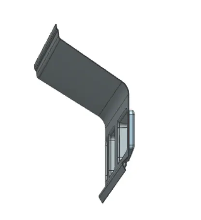
Center roof: It helps in providing support to the flat area of the roof,As the name goes ,it is placed at the center of the roof between the front and rear roof rail.
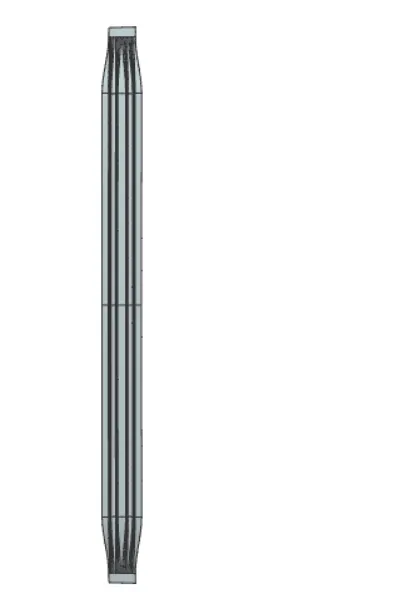
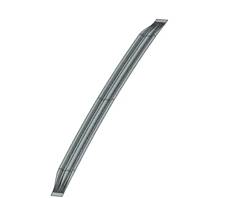
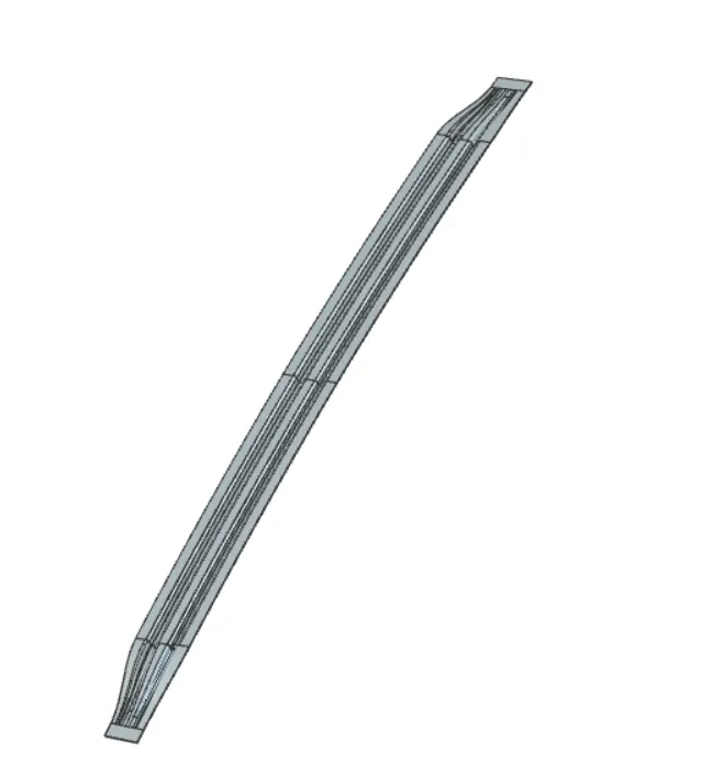
Bow roof:These additional roofs called bow roof are introduced to improve the torsional stiffness and load bearing capacity of the roof structure.The number of bow roof used varies by many facts one to mention is the roof length.
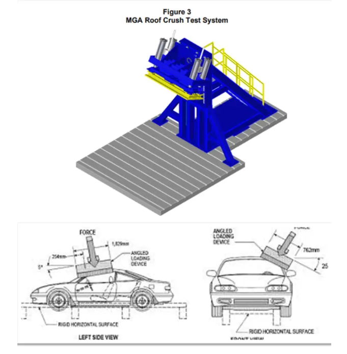
Testing of roof:Roof strength evaluation are conducted an a quasi -static test system manufactured by MGA research corportion
The system consists of an upright assembly and an attched loading head that can be fixed at varying heights from the ground as well as at pitch angles ranging from -5 to +5 degree to accommodate testing on the driver or passenger side.
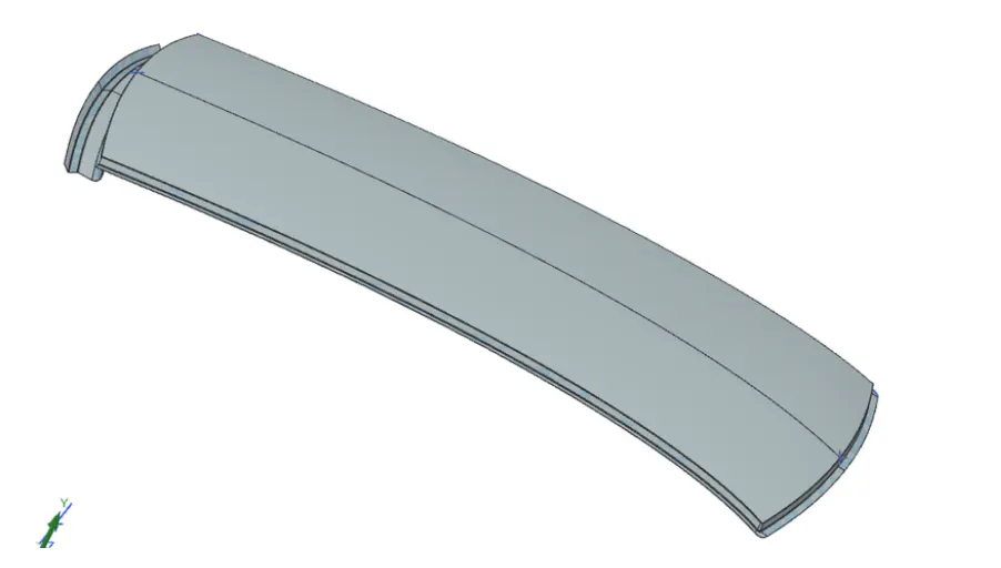
Roof:
Two HR A-36 -W10x88 I-beams are mounted on the bed plate perpendicular to the longitudinal axis of the platen.The vehicle with attched rocker panel support system is placed on these beams.The v ehicle is adjusted so that.
- The longitudinal centerline of platen is within 10mm of the initial roof contact point.
- The yaw angle of the vehicle relative to the longitudinal axis of the platen is 0± 0.5 degrees.
- The midpoint of the platen's forward edge is 254± 10mm forward of the most forward point of the roof lying on the vehicle's longitudinal centerline.
- The pitch angle of the vehicle matches the on road angle ,while also accounting for any difference between the vehicle and platen pitch angle and the nominal -5 degrees.The maximum combined difference of the vehicle and platen pitch angles from their targets is ± 0.5 degrees.If necessary to achieve this angle,shims are inserted between the rocker panel supports and theW10x88 I-Beams attached to the bed plate.
- Once the vehicle is positioned correctly,the rocker panel supports are clamped to the two perpendicular I beams,and the beams are marked to allow confirmation that the vehicle position is maintained during the test.
- For body-on -frame vehicles,the frame is supported to prevent the weight of the chassis from sterring the body at the body mounts.The roof is crushed to a minimum dsplacement of 127mm at a nominal rate 5mm/second.
- Some tests are conducted to a greater displacement to collect additional strength data for research purposes.Force data are recoreded from five load cells(Interface inc model 1220) attched to the loading platen.
- Displacement data are recorded from four linear variable displacement transducers(LVDTs)(MTS Temposonic Model GH)Integrated into the hydraulic actuators.Figure 4 shows the locations of the load cells and LVDTs on the loading platen.
- Force and displacement data are collected with a national instruments USB-6210 data acquision system and reported at 100 Hz.These data are based on a sampling rate of 2000Hz,with every 20 points being averaged to produce the output data at 100Hz.
- The displacement time histories from the LVDTs are compared to verify that the platen's roll angle and pitch were maintained at 25± 0.5 degree and -5 ± 0.5 degrees,Respectively.
- The pre crash and post -crash conditions of each test vehicle are documented with still photographs the postion of the vehicle in the test fixture is also recorded motion picture photography is made of the test with real-time video cameras.
Calculations:For our study we are considering the following conditions for testing the roof.
Heat distortion criteria:The heat distotion study plays a major role in sheet metal usage.Heat distortion temperature is a temperature limit above which the material canot be used for the structural applications.This study is used to predict the heat distortion temperarature at where the material starts to soften when exposed to a fixed load at elevated temperature in order to avoid bending or damanges on the roof based on the heat distortion temperature,this study will predict the bow roof postion which helps to strengthen the roof.
Bow-roof prediction formula
W=(1.73x10^(-3)xL)+(1.85x10^(-8)x(R^2)/t)+(1.10x10^(-3)xl)-2.68
where
L-Roof length in x direction
R-Roof curvature
R=2(Rx*Ry)/(Rx+Ry)
Rx- X curvature
Ry- Y curvature
t-Roof plate tickness
l=Bow roof span
Judgement condition :ok <2.7
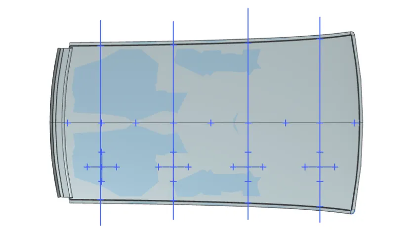
For the above we can find record and calculation as shown below:

From the above table we can conclude that the positions at which the bow roofs are placed satisfy the heat distortion condition and is good to go for manufacturing.
Snow load criteria:
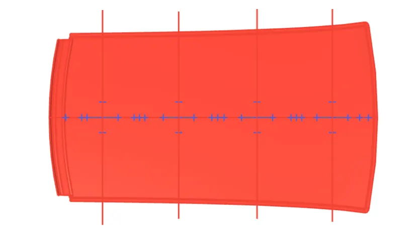
This test is done to know how is the roof behaving when there is a snow over,Normally due to the snow weight the dent will happen.But the roof should be designed in such a way that when the snow is removal the roof should go its orginal position.This is the basic requirements for snow load criteria.
Qr = (lyxt2)/(α x s x((Rx+Ry)/2)2x10^-8)
Where
α =My x Lx2x10-12,My=Y(Ly-Y)
Judgement condition =Qr ≥3.1
250 ≤ s ≤ 380 t=Roof plate thickness
Ly=Distance between the front and rear roof rail on the vehicle along with 0Y
Y=Distance front roof rail to roof Bow
s=Distance for which roof Bow bears divided load
s=L1/2 +L2/2
ly=Geometrical moment of inertia of roof bow
Rx=Lateral direction curvature radius of roof panel Y crodd seccion on roof bow
Ry=Longitudinal direction curvature radius of the roof panel X cross section on roof bow
Section Analysis:
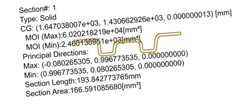
Bow roof 1:
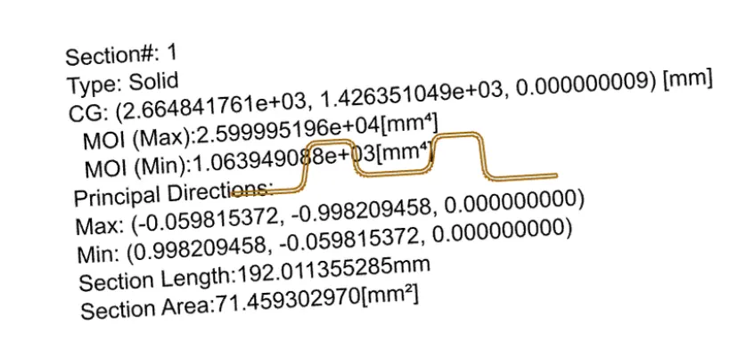
Bow roof 2:
Center roof:
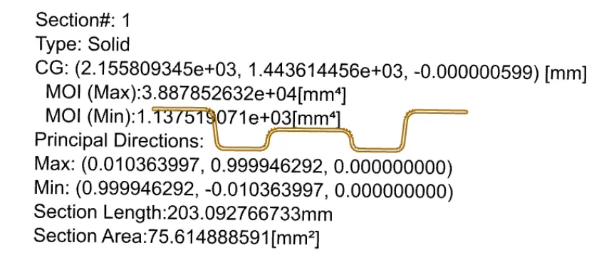
For the above we find record and calculate as shown below:

From the above table we can conclude that the postions at which the bow roofs are placed satify the snow criteria except the bow roof 2.Thus to improve we can add embosses to the roof to increase the strength of the roof.
Draft analysis:
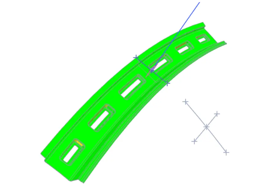
The draft analysis command enables you to detect if the part you drafted will be easily removed this type of analysis is performed based on color ranges indenfying zones on the analyzed element where the deviation from the draft direction at any point corresponds to specified values.
Minimum draft angle of 7degree is considered for analysis,Green color on the parts that all face along the tooling direction has positive draft angle greater than 7degree and passed in analysis:
Front roof rail:
Rear roof rail:
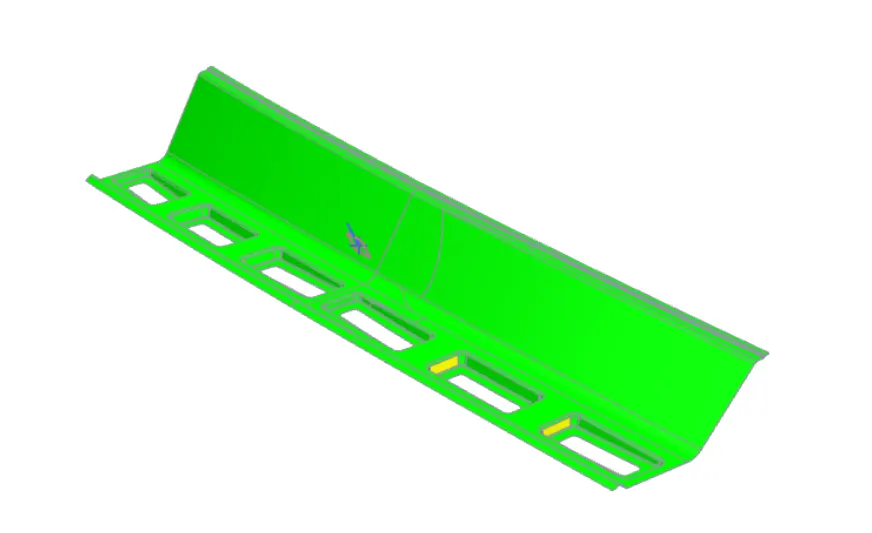
Center roof:
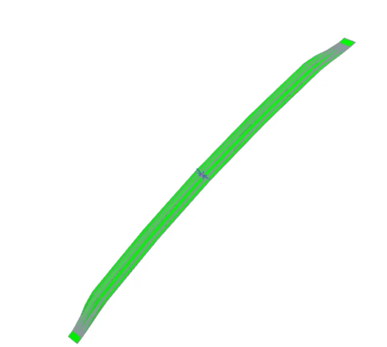
Bow roof 1:
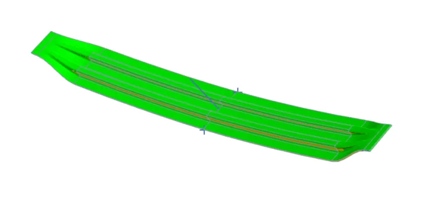
Bow roof 2:
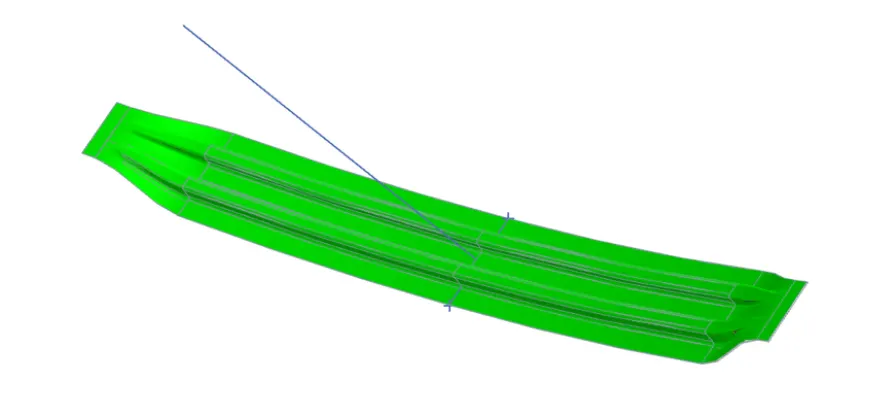
Views of Roof assembly:
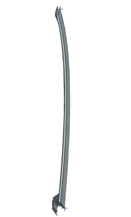
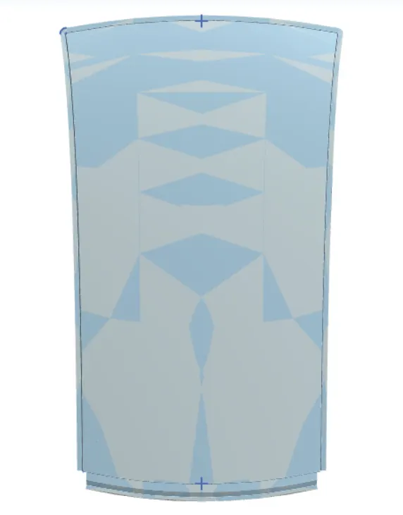
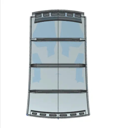
Conclusion:We design the roof ,front roof rail,Center roof rails and rear roof rails according to the master cross section drawing,conduct moment of inertia and design analysis and vaerify the feasibility of manufacturing.