Roof Crush - BIW
Roof Crush - BIW
Aim: To create deck setup, analyse the results for Roof Crush Neon BIW and request for time history plots.
Objective:
1. To check the unit system and either follow[Mg mm s] or [Kg mm ms].
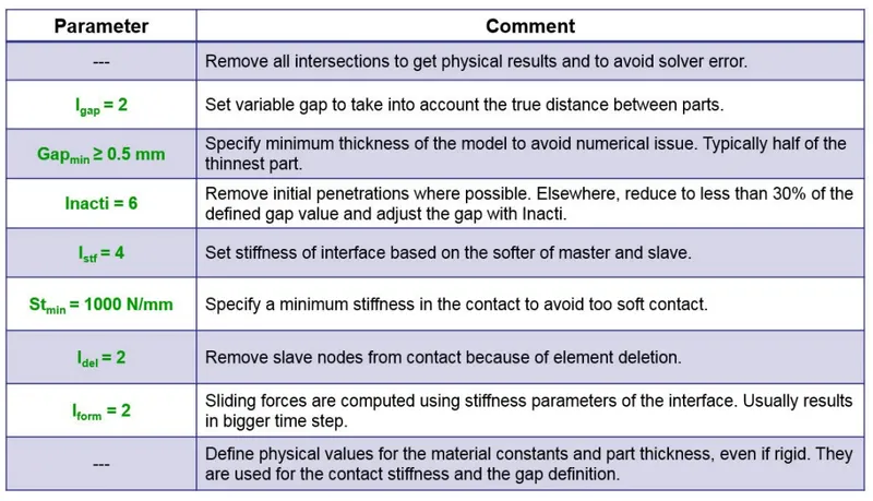
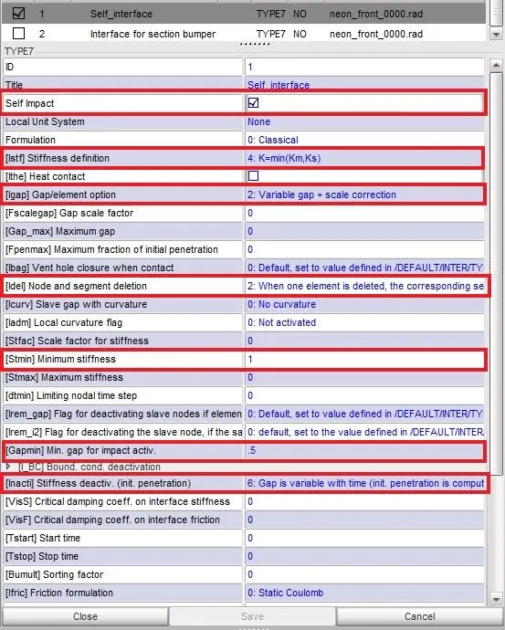
2. To create appropriate interface ,friction 0.2 and recommended parameters.
3. to make sure of no penetrations and intersections.
4. To Transform an impactor.
5. keep the suspension shock tower nodes locked in Z.
6. The impactor assembly contains a spring attached for stability. Create a BCS collector to fix the free end of the spring. Create a moving SKEW to define the direction normal to the impactor’s face. Create a BCS collector to guide the master node of the impactor rigid body so that it is free to translate normal to the face of the impactor, but is fixed in all other DOFs.
7. Imposed Displacement: Impose the velocity of the impactor starting from 0 mm/s at t = 0. The displacement of the impactor should be 200 mm @ 200 ms. Avoid abrupt changes in the acceleration of the impactor.
8. Control Cards
a. /ANALY card.
b. /DEF_SHELL card.
c. /DEF_SOLID card, and.
d. /IOFLAG card.
e. /SPMD card.
f. /TITLE card.
8. Engine File
Use a constant nodal time step.
Print time history every 0.0001 seconds.
Solve for 200 ms.
Create an animation file every 0.005 seconds.
9. Include selected output in animation files: Elemental Energy, Elemental equivalent plastic strain, Elemental hourglass energy, Elemental von Mises stress, Nodal added mass, Turn on parallel arithmetic.
10. carry out roof crush test using FMVSS 216 standards.
Introduction:
Crash worthiness is one of the core topics in the passive safety of vehicles and plays an important role in the condition that the impact cannot be avoided. Generally, the analysis of crashworthiness is based on the related crash responses, i.e. the displacement, velocity and acceleration, of critical parts of a vehicle in full car crash tests. However, these tests are required appropriate facilities, one or more cars with measuring devices, experienced staff and a long time to prepare. It means they are complicated, expensive, long-lasting and therefore not easy to realize. This is especially true in the early stage of vehicle design. Therefore, vehicle designers and researchers made a lot of effort to build numerical models to describe the crash processes. Up to now, various technologies are used to model the vehicle crash. Typical crash models may be classified into three broad categories
1) Detailed nonlinear finite element models.
2) Multi body models and multi body based lumped parameter models.
3) Functional approximation or response surface models.[1].
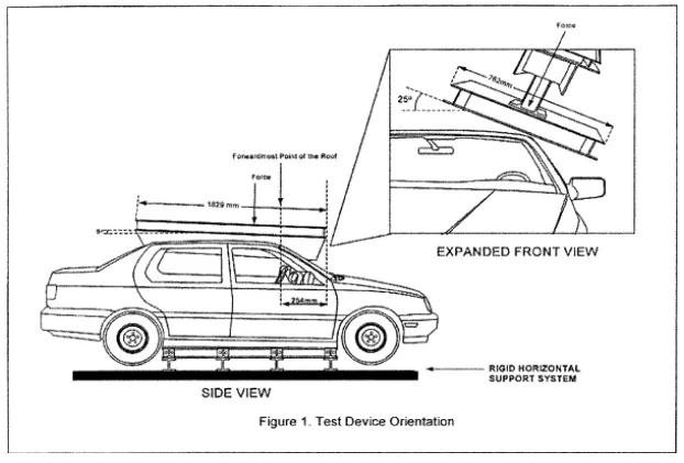
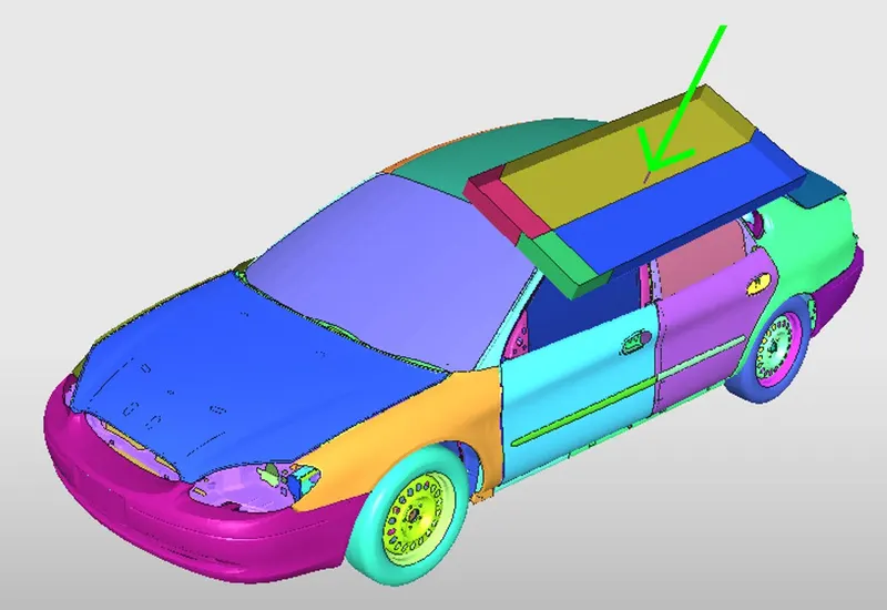
Rollover accidents of a car are the most occurring accidents we see in our daily lives. The passenger experience major injuries like neck, head and spine injuries. So to reduce the injuries of a passenger from major fatalities is to provide safety in the car. The safety is provided by seat belts as well as airbags during accidents. The passenger must have sufficient space for survival in the car during accidents. The roof of the car must have high strength to resist the crush force to avail the passenger space for survival.
FMVSS 216
Under the current version of FMVSS No. 216, vehicles must meet the standard’s requirements for both the driver and passenger sides of the vehicle. Thus, roof crush resistance protection is required for both the driver and passenger sides of the vehicle. The standard specifies a single-sided test. While a vehicle must meet the standard’s test requirements, regardless of whether it is tested on the driver or passenger side, a particular vehicle is tested on only one side.
Resistive Force = Strength to weight ratio*Gross weight of the Vehicle
Strength to weight ratio = Resistive Force*Gross weight of the Vehicle = 3
Setup Procedure
1. Import the file:
In the data we have two files
1.1. Neon_roof_0000.rad and FMVSS_216_ROOF_IMPACTOR_coarse_00001.rad (starter input file): Which has all data required for the solver such as model information, elements, nodes, loads, boundary condition etc.
1.2. Neon_roof_0001.rad (engine input file): Which has all data required for the radioss engine i.e speed , time step, run time, what all data we want as output.
To import file,
a. change user profile to radioss Because we are using solver as Radioss
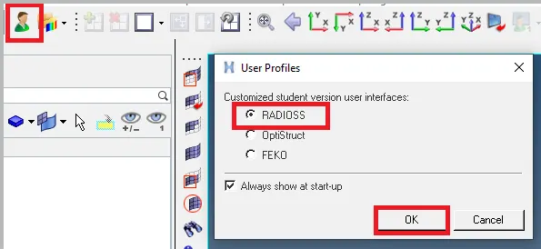
b. File>Import>Solver deck. we can see the new tab where options available for browse file. Browse the file FIRST_RUN_0000.rad (starter input file),
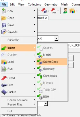
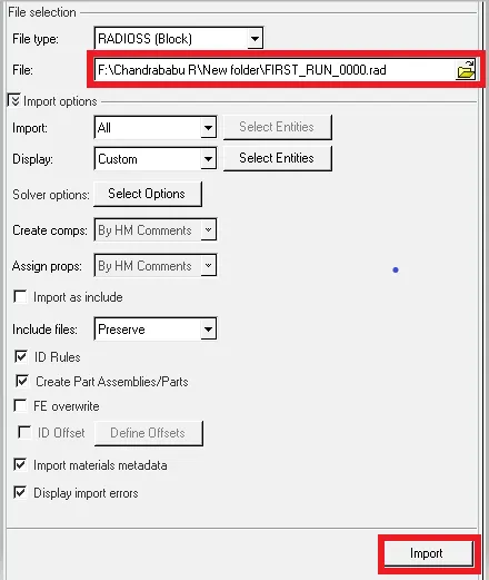
c. Click on import so we can see imported files required for the solver such as model information, elements, nodes, loads, boundary condition etc. Show in the fig. 1.1 (both hypermesh and Crash)
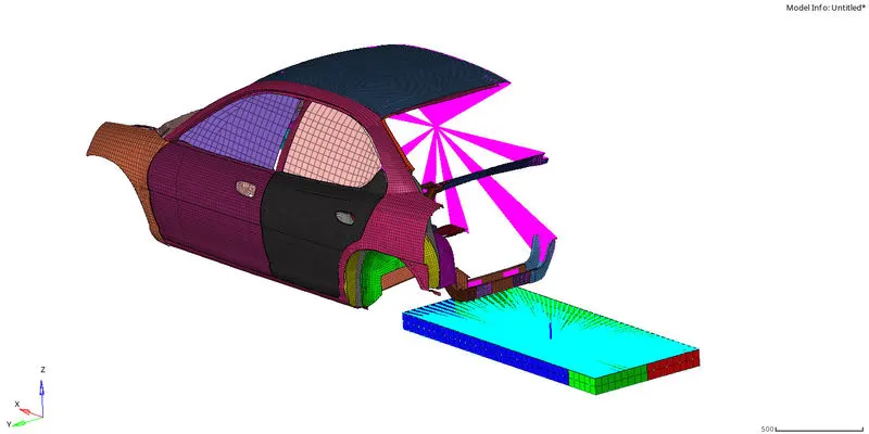
Fig.1.1: Import file
2. Setup for crash: Here some setups are done by Crash and remaining setups are done by Hypermesh.
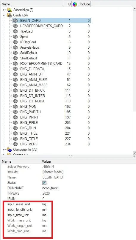
2.1. Check the unit system: To check for the unit system used in the model by clicking on model>cards>BEGIN_CARD it's in Kg-mm-ms.
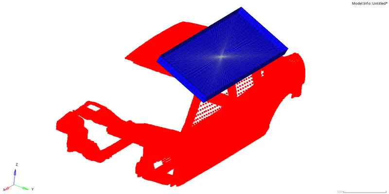
Positioning of the impacter:
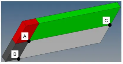
180° rotation about the global z-axis with the point opposite to C as base point
25° rotation about the axis through axis AC
translation of impactor to position show in the fig bolow
3. Create interface: Here required 2 contact interfaces one is for self interface and other one is Impactor and car. Both interfaces are having Recommendations interfaces with gap mim 0.5 and friction 0.2.
3.1. Self interface: Self interface is created in HyperCrash. To create
a. Right click on tab area> Solver > INTER >Type 7
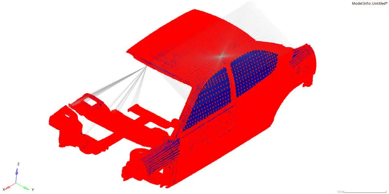
b. Edit the and apply all Recommendations interfaces. and select the self impact option.
3.2. Interface for Bumper: Similarly create Contact interface. In fig 3.1 shows the both interfaces.
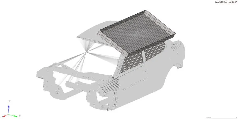
Fig.3.1: Contact Interface
4. Check Initial penetrations and intersection: To check Click on Tools > check penetrations > select parts > click on check penetration. In the figure 4.1 can see the procedure and results
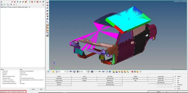
Fig.4.1: Initial penetrations and intersection
5. Create a moving SKEW: In order define the direction normal to the impactor’s face. It is a projection reference to define the local quantities with respect to the global reference. In fact, the origin of the skew remains at the initial position during the motion even though a moving skew is defined. In this case, a simple projection matrix is used to compute the kinematic quantities in the reference.
a. Solver > SKEW> mov
b. Select the coordinate system type you want to create.
c. Select the node that defines the origin by selecting it in the modeling window, or by entering the node ID.
d. x-axis node: Select the node that defines the x direction by selecting it in the modeling window, or by entering the node ID.
e. xy-plane node: The following Output requests are asked in the given problem.Select the node that defines the xy plane by selecting it in the modeling window, or by entering the node ID.
f. relative size: Specify how large, in model units, systems are displayed relative to the model size.
In fig. 5.1 shows the moving SKEW
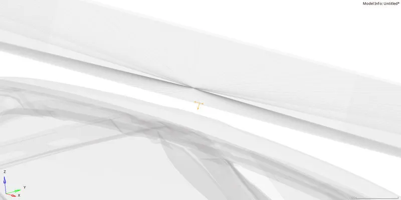
Fig. 5.1 Moving SKEW
6. Boundary condition : Defines boundary conditions on node groups for translational and rotational motion. In order Restrict the motion of suspension nodes, Rigid connection at RH side , impactor motion and Create a BCS
collector to fix the free end of the spring.
keep the suspension shock tower nodes locked in Z.
a. Solver > Create > Boundary condition > BCS
2. The boundary conditions will be applied only to nodes that belong to a node group. so that, select the nodes.
3. Constrain or lock by checking DOF as per requirement here keep the suspension shock tower nodes locked in Z. show in the fig 6.1
| Sl.No | Axis | Direction Of Movement |
| 1 | Dof 1 | Translational along +X,-X |
| 2 | Dof 2 | Translational along +Y,-Y |
| 3 | Dof 3 | Translational along +Z,-Z |
| 4 | Dof 4 | Rotation X |
| 5 | Dof 5 | Rotation Y |
| 6 | Dof 6 | Rotation Z |
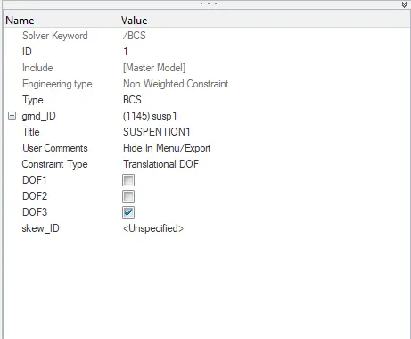
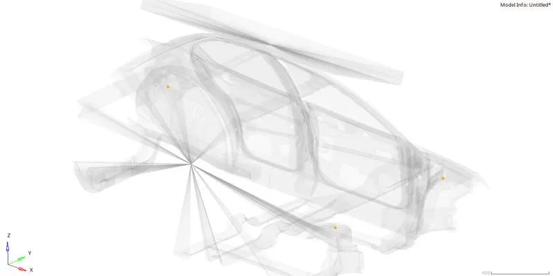
Fig. 6.1 suspension shock tower nodes locked in Z
Rigid connection at RH side should be fixed in all directions.
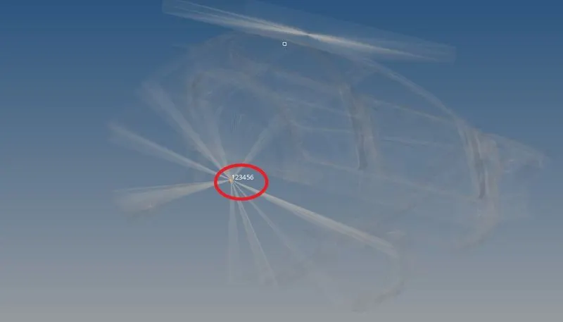
Impactor Boundary Conditions: similarly Do for impactor, so that impactor should follow the Conditions below
1. The impactor assembly contains a spring attached for stability. Create a BCS collector to fix the free end of the spring.
2. Create a moving SKEW to define the direction normal to the impactor’s face.
3. Create a BCS collector to guide the master node of the impactor rigid body so that it is free to translate normal to the face of the impactor, but is fixed in all other DOFs. Show in the fig. 6.2
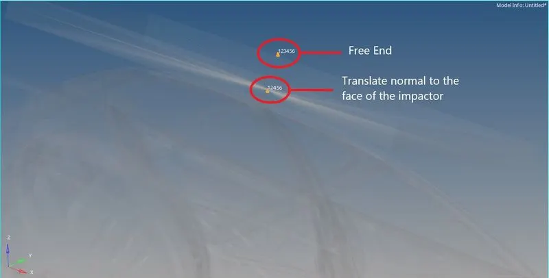
Fig. 6.2: Impactor Boundary Conditions
7. Engine File:
1. Use a constant nodal time step
2. Print time history every 0.0001 seconds
3. Solve for 200 ms
4. Create an animation file every 0.005 seconds
Input the Run time 200ms that is Final time for the run. in engine cards ENG_RUN
Time step: Time step defaults for all elements which is 0.0001 to 0.0005ms (Solver > Create > Engine keywords > DT >DT) . If the time step of a simulation reaches ΔTmin">ΔTmin , then the following actions will happen depending on which element type is controlling the time step. For /BRICK or /QUAD elements, the simulation stops and a restart file is created. For /SHELL or /SH_3N elements, the element controlling the time step is deleted from the simulation. For all other element types, ΔTmin">ΔTmin is not used.
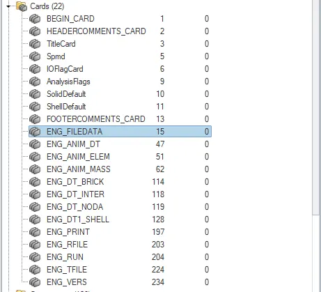
8. Imposed Displacement: Defines imposed displacements on a group of nodes. to create
a. Solver > Create > Boundary condition > IMPDISP
b. Node group on which the imposed displacement is applied. select the node
c. Here we need wrt moving skew so select skew system.
d. Define curve, Go to curves>create >new and enter the values Time and displacement Impose the velocity of the impactor starting from 0 mm/s at t = 0. The displacement of the impactor should be 200 mm @ 200 ms. Avoid abrupt changes in the acceleration of the impactor.Search distance 1000 (Distance for slave search).Give sliding with friction of 0.1.
In the fig. 8.1 shows IMPDISP
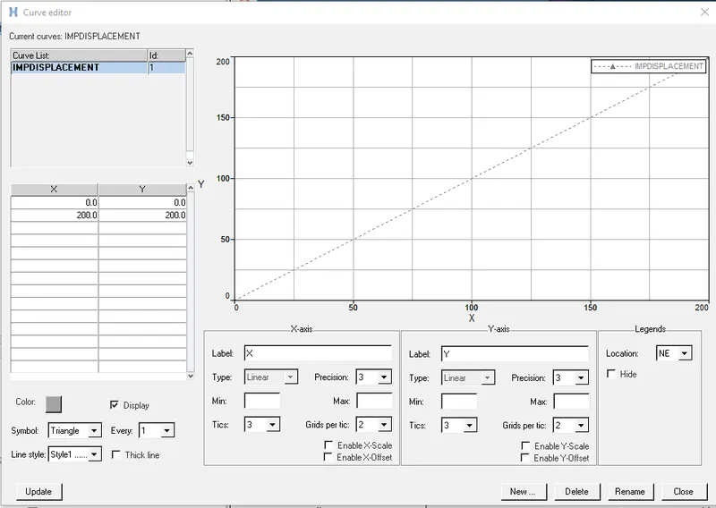
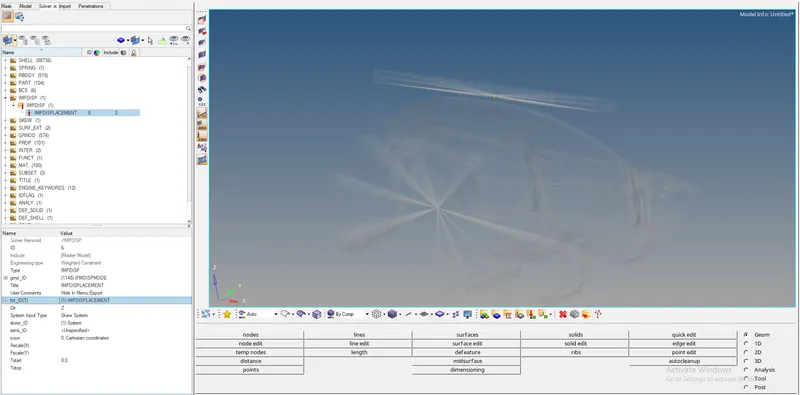
Fig. 8.1: IMPDISP
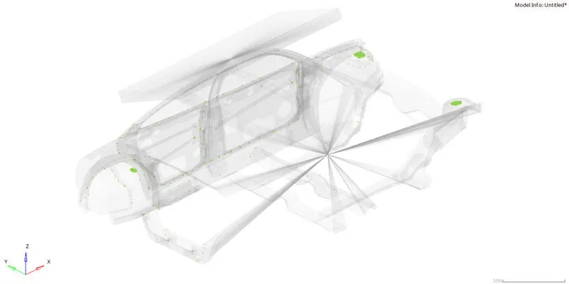
9. Missing Connection: because of missing connection b/w components we are getting more energy errors
so create Rbodys connection for all components to connect.
10. Output requests: In output requests we are going to request all required output which we need. To request Solver > Create > TH > select things to record in result.
1. Plot force vs. displacement. Check that the FMVSS 216 target load of 47,000 N (= 3 * GVW) has been met.
2. Plot the energy vs. time curves
Include selected output in animation files:
1. Elemental Energy
2. Elemental equivalent plastic strain
3. Elemental hourglass energy
4. Elemental von Mises stress
5. Nodal added mass
6. Turn on parallel arithmetic
Run simulation Analysis > Radioss
Simulation Results:
In the fig 10.1 shows the simulation for Roof crash of car BIW.
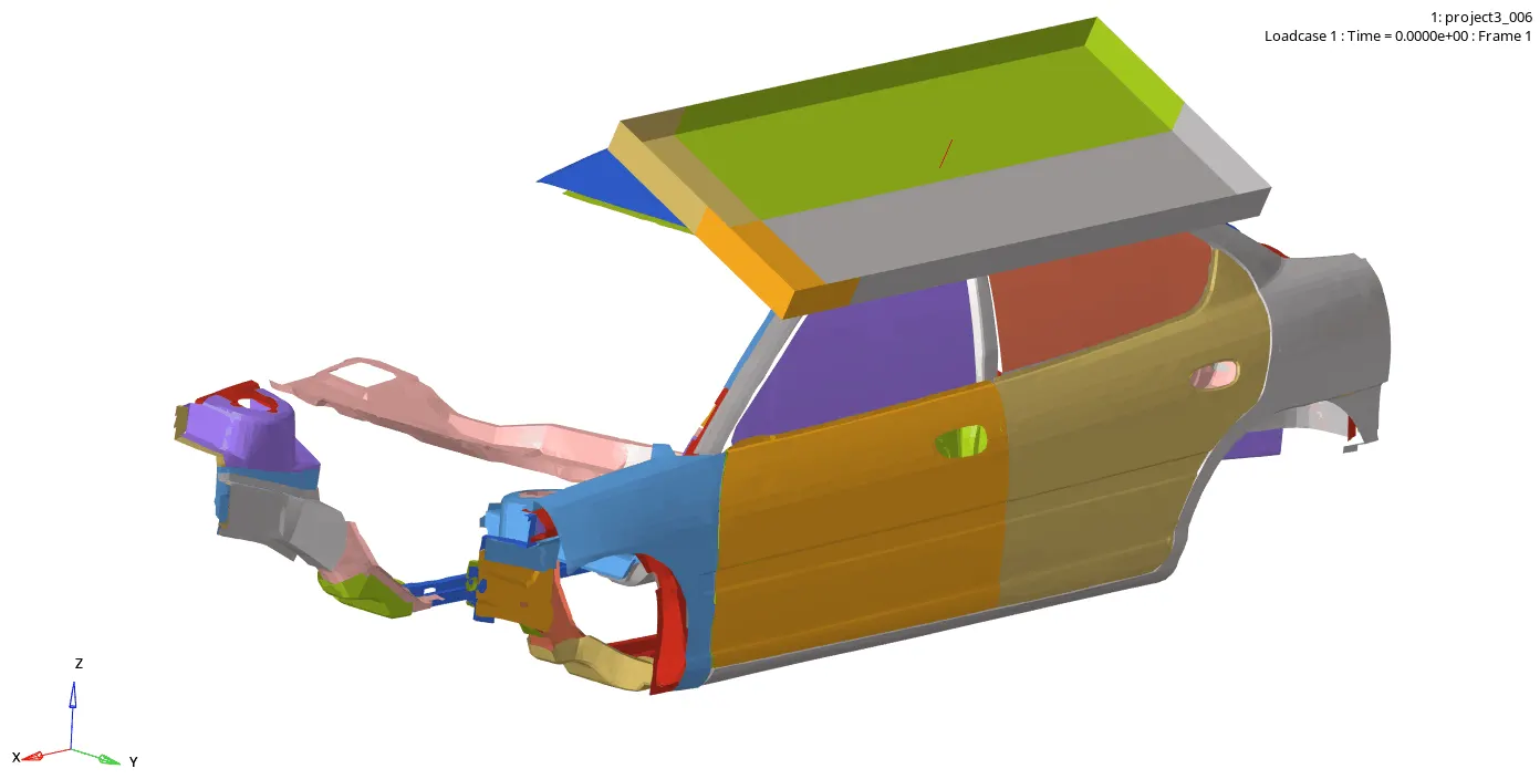
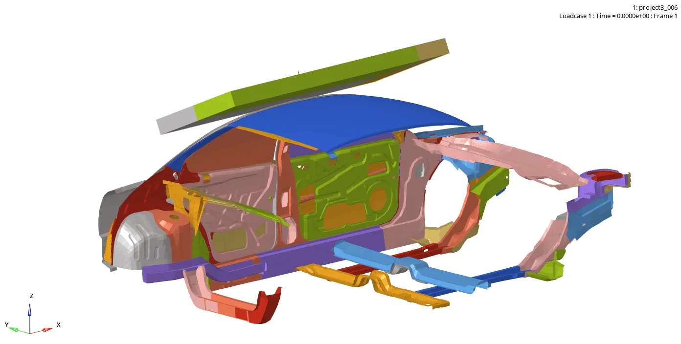
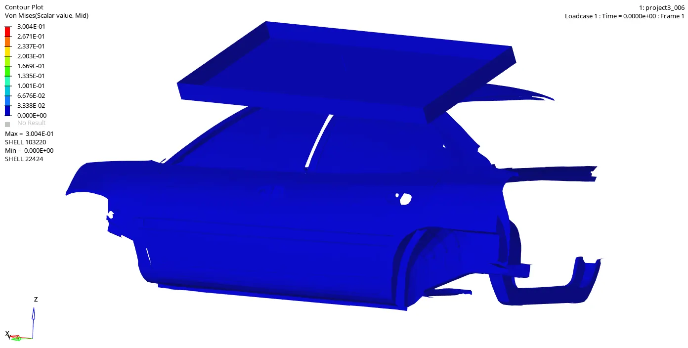
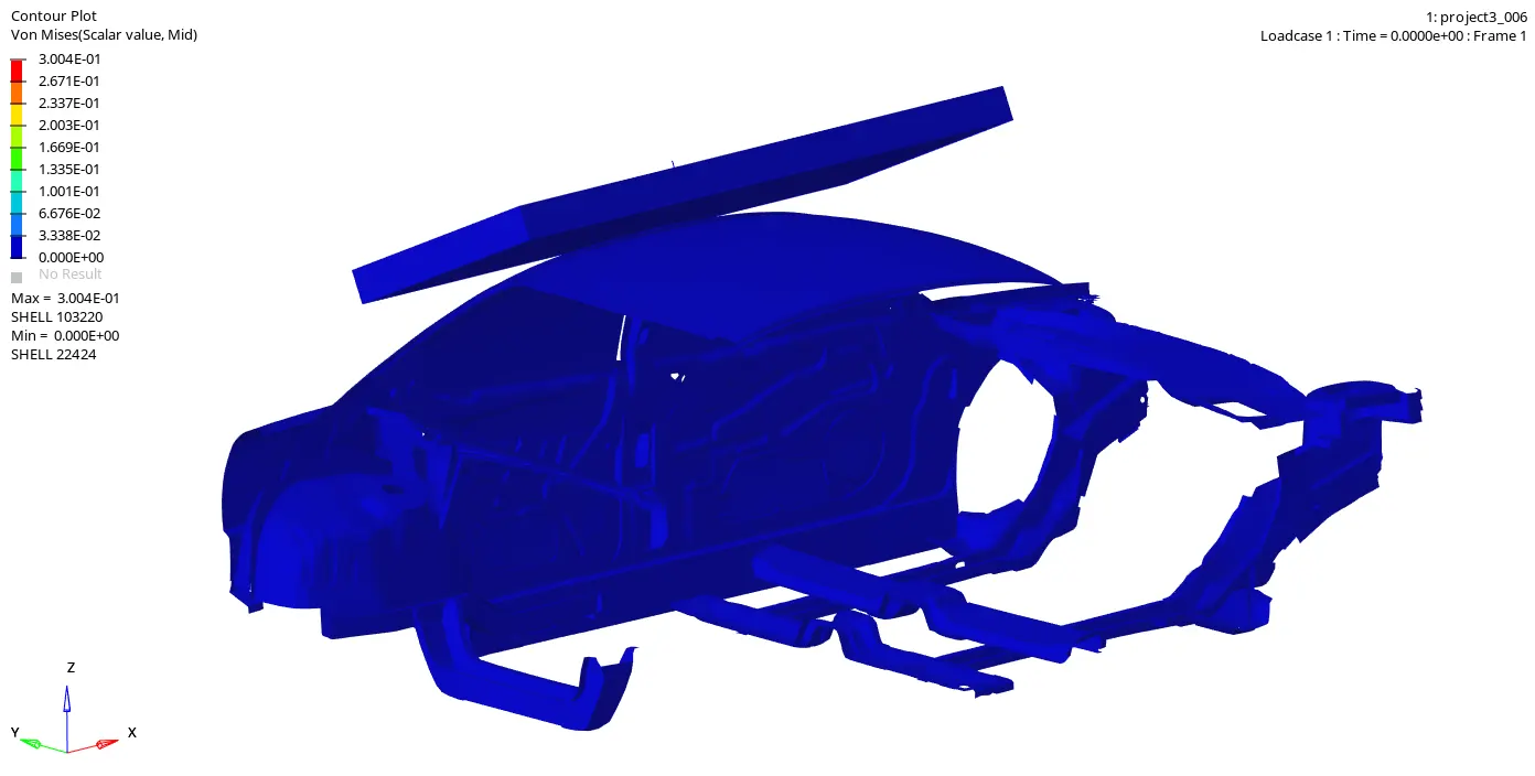
Fig. 10.1: Side pole crash
From the simulation we can see that. Initially B Pillar and roof is contacting the impactor with displacement 0 to 200mm.
Impact versus Quasi Static Simulations
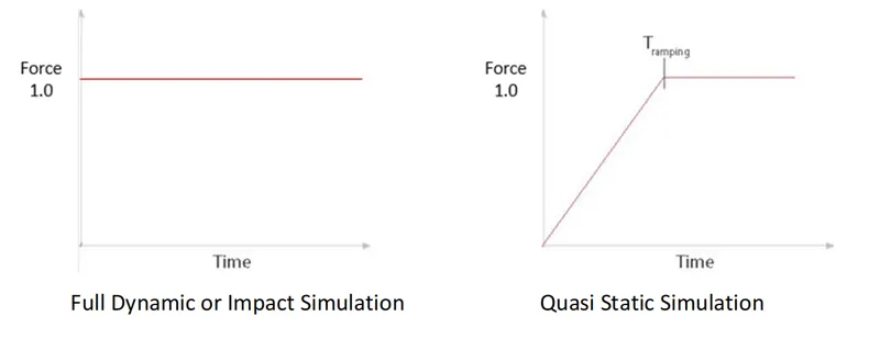
If the excitation frequency is less than one third of the lowest natural frequency of the structure it can be considered a quasi static loading where inertial effect can be neglected. The term Quasi Static is used to represent a slow dynamic process as opposed to a fast dynamic process. The distinction between these two is quite obvious when we see the load application in the following figure, a suddenly applied load (mathematically a heavy side or step input) will result in a displacement two times that of the static displacement of the system. The term Quasi Static simulation is used when we use a dynamic code to produce a static result. It must be remembered that we will get a static or close to static result only if the ramp up time is sufficiently large (i.e. the ramp up slope is not too steep so as to get a close result as same as that as Full dynamic simulation).
quasistatic simulation we have following options:
a. Increase the element length
b. Increase the density of the component , increasing the mass of component
c. Increase the rate of loading
d. Decrease elasticity moduli of the material
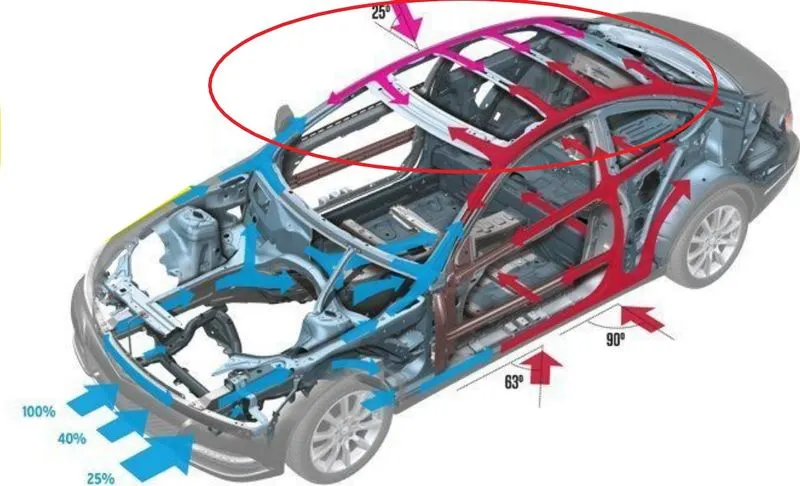
Load-carrying Path and Crash Process: Generally, vehicles have a high relative velocity in the crashes. For this reason,
11. Graphs:
11.1 Energy: Energy, in physics, the capacity for doing work. It may exist in potential, kinetic, thermal, electrical, chemical, nuclear, or other various forms.
In FEA we have Total Energy, Internal Energy, Kinetic energy, Contact energy and hourglass energy
Total Energy (TE): Total Energy is the sum of Internal Energy, Kinetic energy & External Work
Internal Energy (IE): The internal energy of a thermodynamic system is the energy contained within it. It is the energy necessary to create or prepare the system in any given internal state. It does not include the kinetic energy of motion of the system as a whole, nor the potential energy of the system as a whole due to external force fields, including the energy of displacement of the surroundings of the system. It keeps account of the gains and losses of energy of the system that are due to changes in its internal state
Kinetic energy (KE): In physics, the kinetic energy (KE) of an object is the energy that it possesses due to its motion. It is defined as the work needed to accelerate a body of a given mass from rest to its stated velocity.
Contact energy (CE): Contact energy is the energy acting opposite to the system to prevent the penetration acting on the system due to applied load case.
Hourglass energy (HE): This is usually done by adding extra stiffness or viscosity across the diagonal which adds extra strain energy into the system and we call this as Hourglass Energy.
Energy Errors:
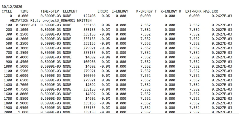
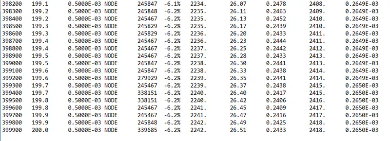
Energy error is 0 to -6.2 % and mass error is 0% this is due to energy is dissipated from the system. In case of under integrated elements, the Hourglass Energy can explain a negative Energy Error since it is not counted in the energy balance.
Results:
11.2. In Roof crashes we have following energy graphs..
1. Initially Impactor is at rest so there is no any energies, once Impactor moving with Imposed Displacement towards Roof with But here Impactor energies are not taken in output.
2. When the Impactor is touching the car with uniform displacement. @ 20ms, so the crush starts on the roof of the car. so KE and TE are starting to increase from zero.
3. Initially IE & KE is zero and only IE increases w,r,t to time until the complete Displacement of 200mm. Because of impactor elements of the car roof and B pillar starts absorbing energy and Change in shape produces the IE, due to IE when it has TE.
we have for the car Total Energy = Internal Energy + Kinetic energy + External Work, (2262 Kg-mm^2/ms^2) Here TE is not depending on external work. There is very less constant Kinetic energy on car BIW only the car is at rest but due to impactor the elements are moving with very less velocity.
As IE increasing, TE also increasing, TE is increasing because of IE & External Work
Contact energy is the energy acting opposite to the system to prevent the penetration acting on the system due to the Impactor.
4. Hourglass energy is constant because both are controlled by elements formulation. here hourglass is controlled by Physical stabilization i.e changing material level in ISHELL is 24 QEPH Shell formulation.
In the fig. 11.2 shown energy graph
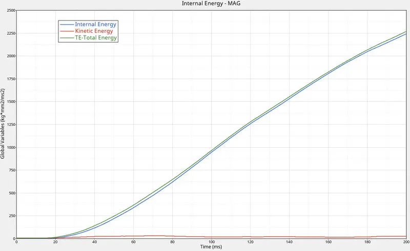
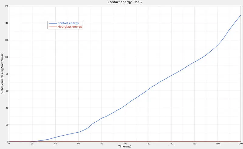
Fig. 11.2: Energy Graph
From the graph we have
a. KE constant = 26 to 32 Kg-mm^2/ms^2 at time 20 to 200 ms.
KE min= 0 Kg-mm^2/ms^2 at time 0 ms.
b. Internal energy max= 2240 Kg-mm^2/ms^2 at time 200 ms^2
Internal energy min= 0 Kg-mm^2/ms^2 at time 0ms^2
c. Contact energy max= 149.3 Kg-mm^2/ms^2 at time 200 ms^2
d. Hourglass energy constant = 0 Kg-mm^2/ms^2 at time 0 to 200ms^2
11.3. Include selected output in animation files: To Include all first we need to create ENG_ANIM_ELEM card. Generates animation files containing element data for the specified result. Options used for beam, spring and truss element types.
/ANIM/ELEM Generates animation files containing element data for the selected result type. These types of data are typically contoured in HyperView.
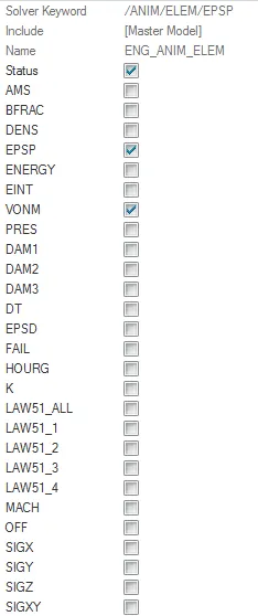
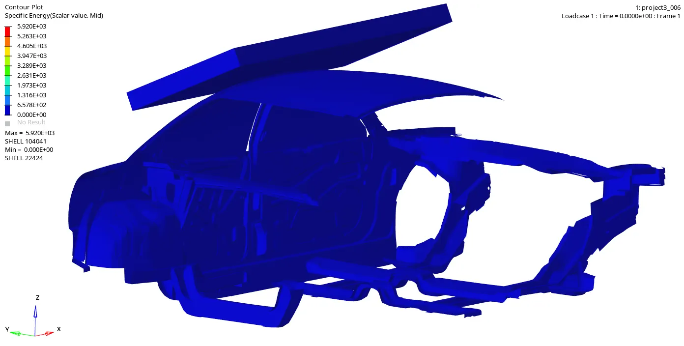
11.3.1. Elemental Energy: Specific energy density (internal energy divided by the element mass).
Energy density is the amount of energy that can be stored in a given mass of a substance or system. The higher the energy density of a system or material, the greater the amount of energy stored in its mass. Energy can be stored in many different types of substances and systems. A material can release energy in four types of reactions. These reactions are nuclear, chemical, electrochemical and electrical. When calculating the amount of energy in a system most often only useful or extractable energy is measured. In scientific equations, energy density is often denoted by U.
Energy density is generally expressed in two ways, although the first is more common:
Volumetric energy density - how much energy a system contains in comparison to its volume; typically expressed in watt-hours per liter (Wh/L) or Megajoules per liter (MJ/L).
Gravimetric energy density (Specific energy) - how much energy a system contains in comparison to its mass; typically expressed in watt-hours per kilogram (Wh/kg), or Megajoules per kilogram (MJ/kg).
Form the graph the Simulation we have Max Elemental Energy 5.92X10^3 J and Min 0 J its very less.
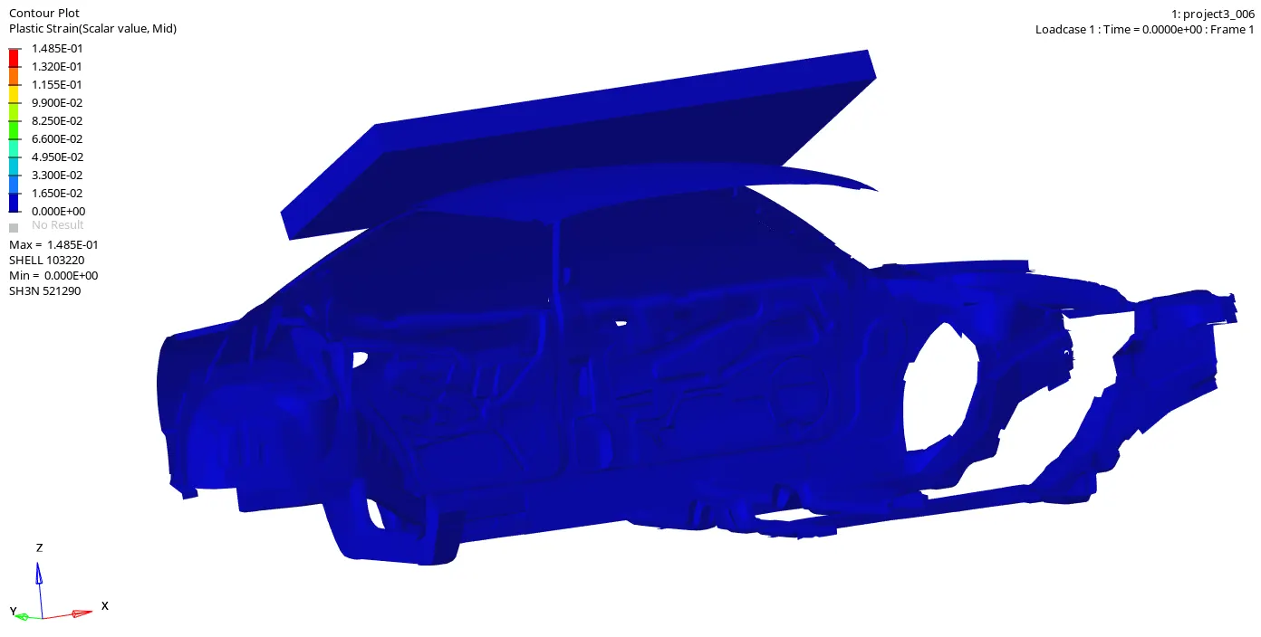
11.3.2. Elemental equivalent plastic strain: plastic strain the strain where the permanent deformation occurs.
Here we can see the permanent deformation occurs and fails at 103220 node number of 0.149GPa. so we can see from the simulation plastic strain found on A B & B pillar. this is because stress produced are greater than the Yield stress so that the model is in Plastic Region.
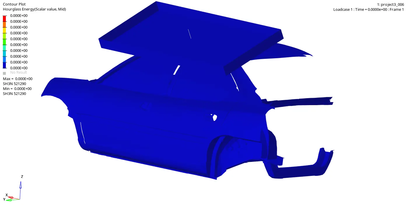
11.3.3. Elemental hourglass energy:
From the simulation we can see that the Hourglass energy is zero because we have used Improved integrated element formulation(QEPH). i.e Physical Stabilization where
Hourglass yield depends on natural yield.
Hourglass loading stiffness depends on natural tangent modulus.
The hourglass treatment is done at the material level.
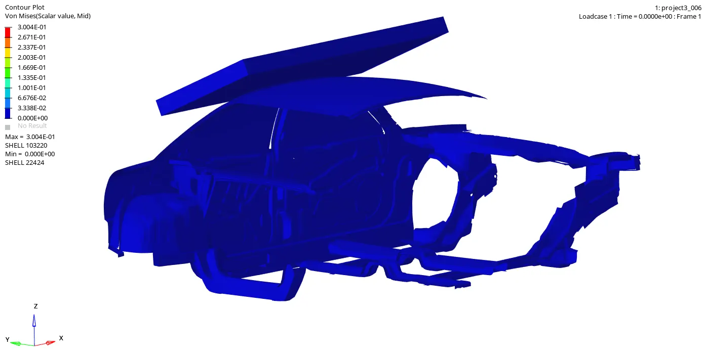
11.3.4. Elemental von Mises stress: Von Mises stress is a value used to determine if a given material will yield or fracture. It is mostly used for ductile materials, such as metals. The von Mises yield criterion states that if the von Mises stress of a material under load is equal or greater than the yield limit of the same material under simple tension then the material will yield.
Maximum Von Mises Stress is 0.305Gpa at Node 103220. From the Simulation we can see that the maximum stress is flowing from car roof to A Pillar, B pillar and B pillar, From A Pillar, B pillar and B pillar to Suspension.
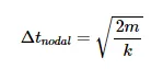
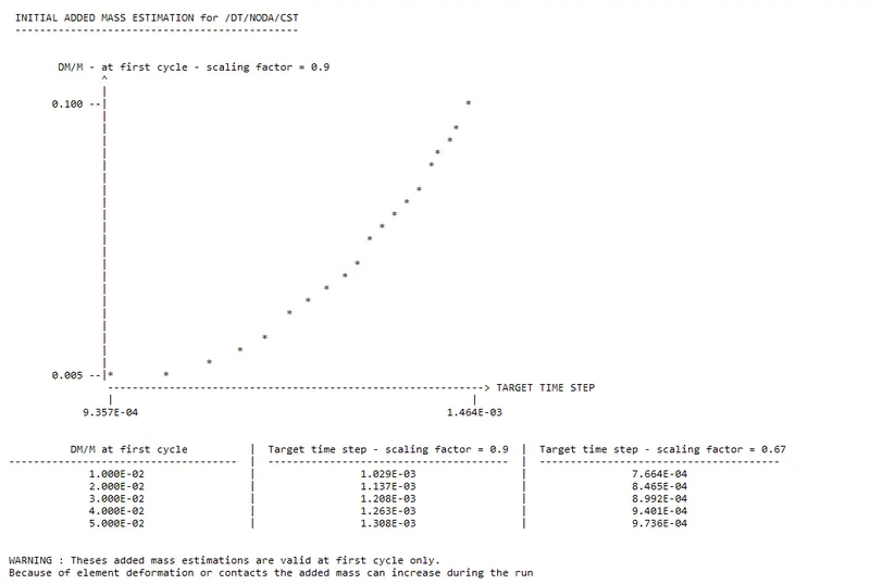
11.3.5. Nodal added mass: The nodal time step control is activated for a simulation by using the option /DT/NODA/Keyword3/Iflag
With the time step of a node in the mesh defined as:
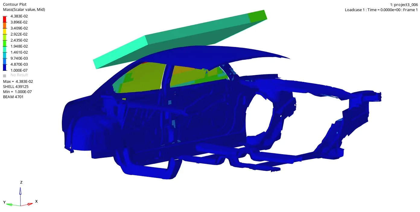
Choose a Time Step for Mass Scaling
Form the 0000.Out file
12.1. Plot Force vs. Displacement: To plot Force vs Displacement first we need plot force vs time and displacement vs time, by taking both graphs we are cross plotting.
11.4.1. From the defined curve and BCS, Impactor moves 200mm wrt time. shown in the fig.12.1 Displacement vs time
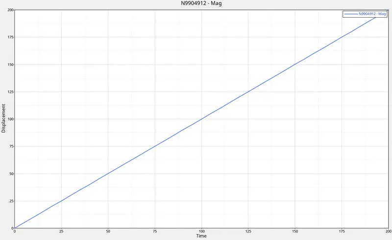
Fig. 12.1: Displacement vs time
12.2 Force developed due to displacement is shown in the fig. 12.2
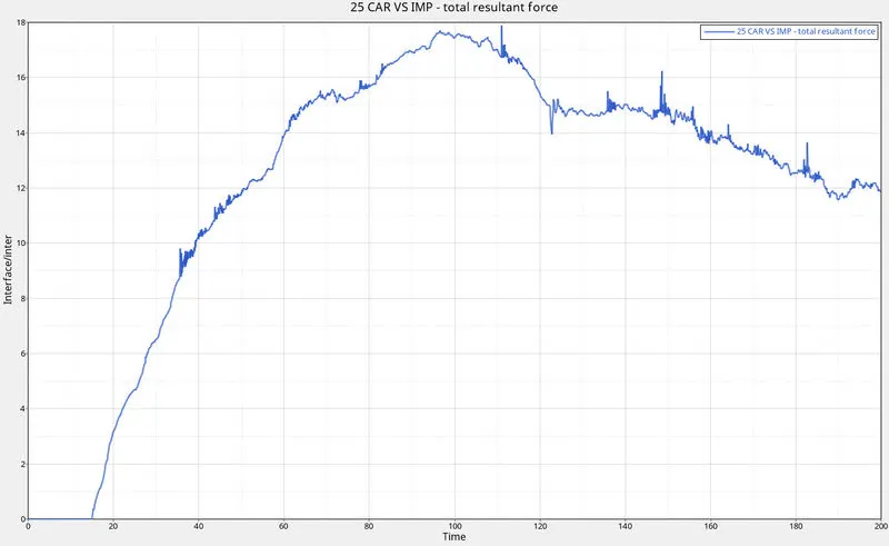
Fig. 12.2: Force vs time
12.3. By cross plotting we have Displacement vs force graph shown in the fig. 12.3
From the plot we have 17.43 KN at 100ms
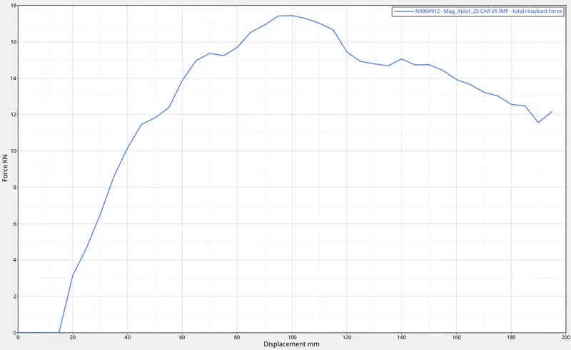
Fig.12.3: Displacement vs Force
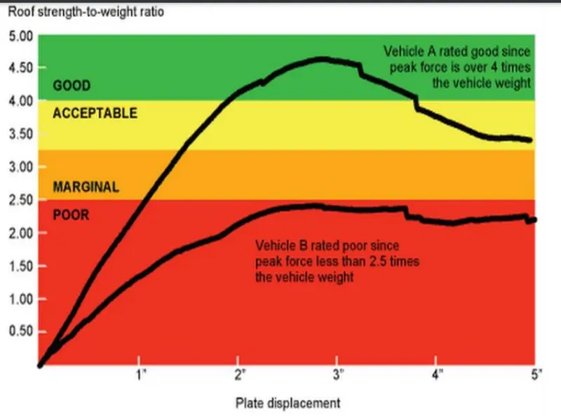
Strength to weight ratio=Resistive Force/Gross weight of the Vehicle
47,000 N (= 3 * GVW) has been met.
Resistive Force = Strength to weight ratio*Gross weight of the Vehicle
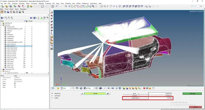
Resistive Force = 3*9.81*174.05 = 5122.29N , this is the theoretical value.
Resistive force is Not exceed the 47000N, the Car is safe
From the graph
we have Resistive Force is 17.43KN = 17430 N
Gross weight of the Vehicle is 174.05*9.81 = 1,707.43 N
Strength to weight ratio=Resistive Force/Gross weight of the Vehicle
Strength to weight ratio = 17430/1,707.43 = 10.2
Strength to weight ratio 10.2 because we taken only BIW Gross weight of car ,
suppose consider the total car weight 700 Kg
Strength to weight ratio = 17430/700*9.81 = 2.5 so it is Marginal
Conclusion: The overall objective of the work was to simulate roof crash and validate the results of the simulations obtained from the Roof crash-test. Simulation was performed using the Radioss software package.
The graphical results obtained all showed that the test models behavior were shown.
Due to the limited number of nodes in the student version some of the biw, engine blocks, suspension system etc are removed, so results are not as in real condition.
It has been observed that Resistive force is Not exceed 47000N, the Car is safe
It has been observed that considering the total car weight 700 Kg the Strength to weight ratio is Marginal.
References
[1] A MODEL OF VEHICLE-FIXED BARRIER FRONTAL CRASH AND ITS APPLICATION IN THE ESTIMATION OF CRASH KINEMATICS, Zuolong, Wei Hamid Reza, Krimi Kjell Gunnar, Robbersmyr University of Agder Norway Paper Number 15-0161