Roof Crush analysis
AIM:
To perform Roof Crush Analysis on the BIW model and Observe Changes in The model with respect to the Different Boundary Conditions in the Simulation and Graph.
INTRODUCTION:
Crash analysis is an integral part of safety analysis and is often completed at intersections and corridors. The crash analysis can help assess concerns and help determine potential improvement options. A Crash test is a form of destructive testing usually performed in order to ensure safe design standards.
New Car Assessment Program (NCAP):
It is a government car safety program tasked with evaluating new automobile designs for performance against various safety threats.
Standard crash tests performed by NCAP:
1:Frontal offset testing (64 km/h proposed)
2.Side-impact testing
3.Pedestrian protection testing
4.Rear impact testing
5.Child dummy dynamic crash testing
FMVSS ( Federal Motor Vehicle safety standards)
Federal Motor Vehicle Safety Standards (FMVSS) are US federal Vehicle Regulations specifying design, construction, performance, and durability requirements for motor vehicles and regulated Automobile safety-related components, systems, and design features. They are the U.S. counterpart to the UN Regulations developed by the World Forum For Harmonization of Vehicle Regulations and recognized to a varying degree by most countries except the United States.
BIW (BODY IN WHITE)
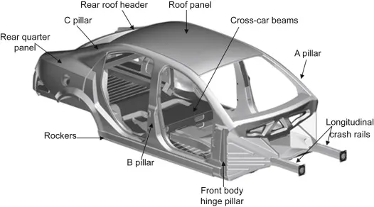
Body in white (BIW) is the stage in Automobile Manufacturing in which a car body's frame has been joined together, that is before painting and before the motor, chassis sub-assemblies, or trim (glass, door locks/handles, seats, upholstery, electronics, etc.) have been integrated into the structure. Assembly involves different techniques such as Welding (spot, MIG/MAG), Riveting, clinching, bonding, and laser Brazing.
ROOF CRUSH:
PROCEDURE:
Case setup & Execution:
1. Import the given model "neon_roof_0000" into Hypermesh.
2.Import "FMVSS_216_ROOF_IMPACTOR_
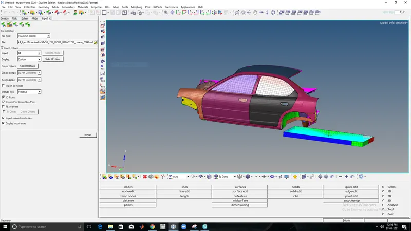
3.The Impactor should be at the top of the Body.
4.The Impactor is Moved to the top of the car by using rotation and translation commands which are available in the tools panel.
5.The Angle and Coordinates of the Rotation and Translation Are given in the Model Info before.
- A 180° rotation about the global z-axis with the point opposite to C as the base point
- A 5° rotation about the axis through axis AB
- A 25° rotation about the axis through axis AC
- A translation to put point A at global ( -3500.00, 584.822, 1343.06)
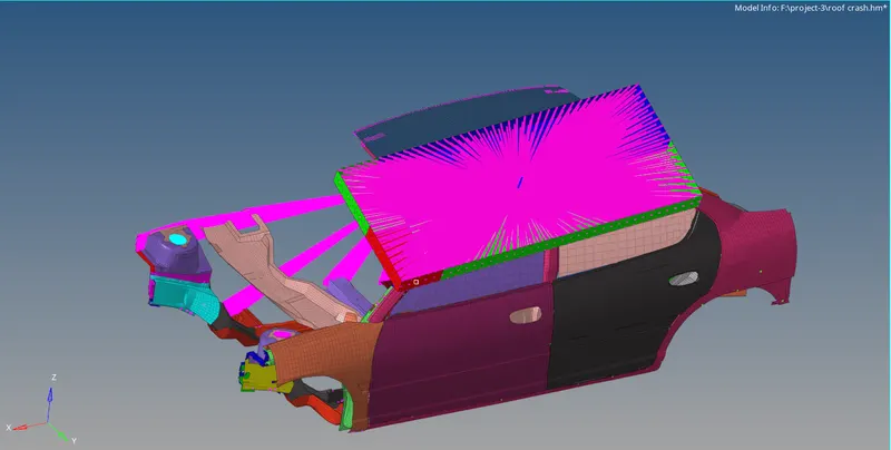
6. After aligning the Impactor in the Desired coordinates the model is exported and saved in a different folder.
7. The saved Model "roof_crash_edited" is imported into Hypercrash with the unit system as "Kg mm ms"
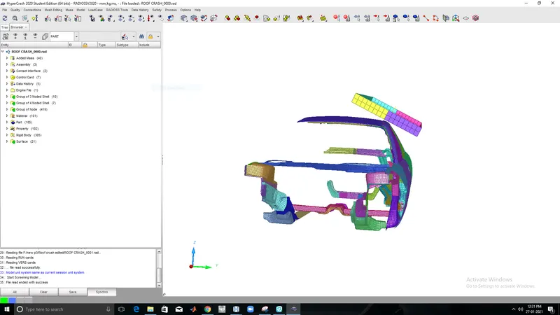
8. The unsupported Cards are deleted and the model checker is executed to see the errors and warnings in the model.
Perform model check and penetration check in the Quality menu in Hyper crash before applying the conditions.
9.Note the errors and Warnings showed and keep them as a reference for later use.
STEP-1: CREATING CONTACT INTERFACE
1. A contact interface should be defined to view the contact energy.
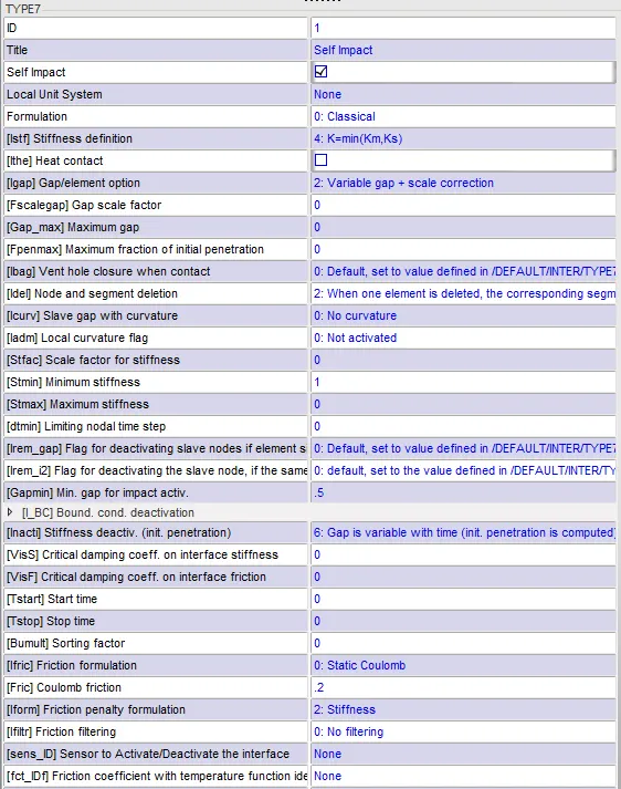
2. Here the type-7 Contact is used (Node to Surface), because of its high accuracy and correct physical representation.
3.The contact interface is defined as Two cases.
4.In case-1 Self contact is defined as excluding the rigid wall the BIW acts as master as well as the slave.
Self impact-full body:
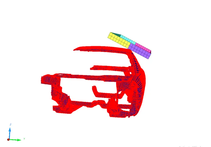
5. The red color in the image Indicates the nodes with both master and slave, whereas the master is defined as blue and the red as Slave.
6. In case-2 the Rigid wall is defined as master and the BIW is defined as the Slave, as we need to analyze the deformations in the Body it is defined as a slave.
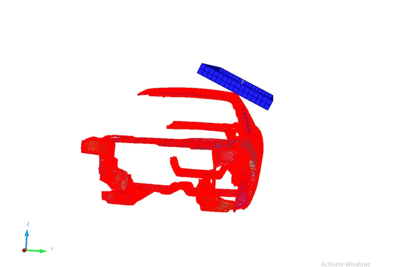
7. In the above image, the master is defined as blue and the red as Slave.
After all these Steps The model is Exported as Radioss, and opened in Hypermesh.
STEP-2: CREATING SUSPENSION NODES:
A set of Rigids was created in the place of the Suspension region before Defining the Boundary conditions.
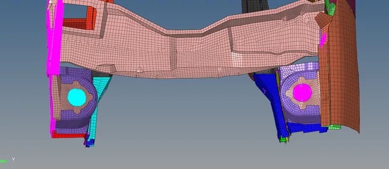
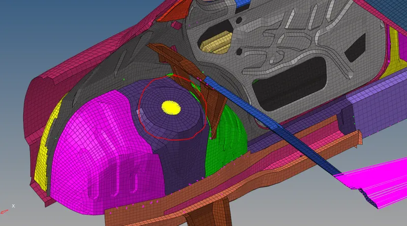
The Card image was set to none for these rigids.
STEP-3: DEFINING SKEW:
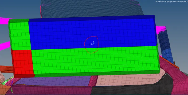
1. As the Impactor is inclined a separate movement in different Cross-sections should be defined.
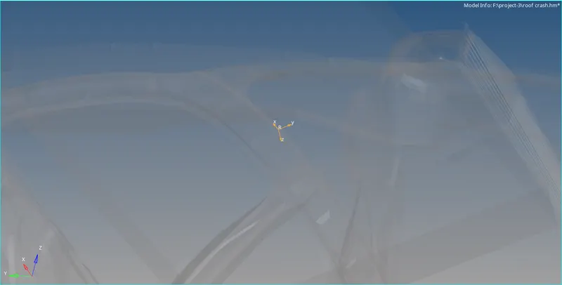
2. For defining The cross-section a Moving Skew is Created.
3.For creating Moving Skew, press right-click on the solver area > Skew > Mov is selected .
4. Define the cross-section with respect to the Impactor where the Skew Z-axis should be parallel opp to the global Z-axis.
STEP-4 CREATION OF BOUNDARY CONDITIONS:
BC-1:
1.In the Solver area press Right click > Boundary conditions > BCS and name it as Suspension nodes.
2.In the grnd_ID select the set Master nodes in the Rigids created in the Suspension Region.
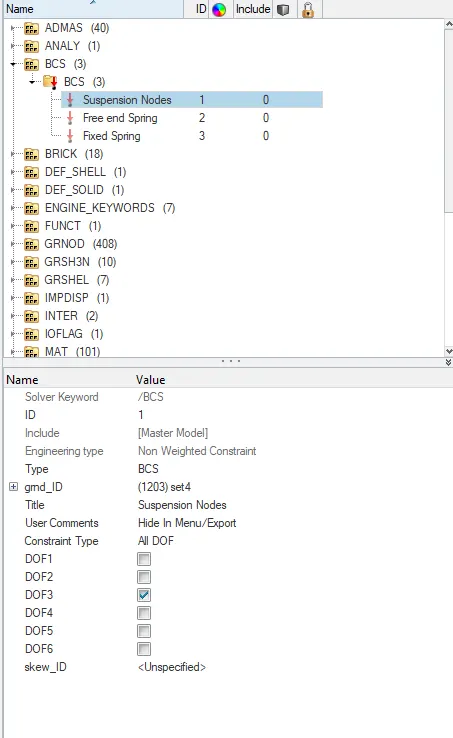
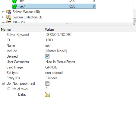
3. In the Constraint Type The Suspension nodes are locked in moving Z-direction DOF-3.
BC-2:
1. In the Solver area press Right click > Boundary conditions > BCS and name it as Free end Spring.
2. create a separate set and in the Entity_id define a node in the free end of the Spring in the Model area.
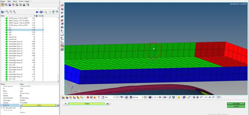
3.In the grnd_ID select the Node set Created for the Free end spring.
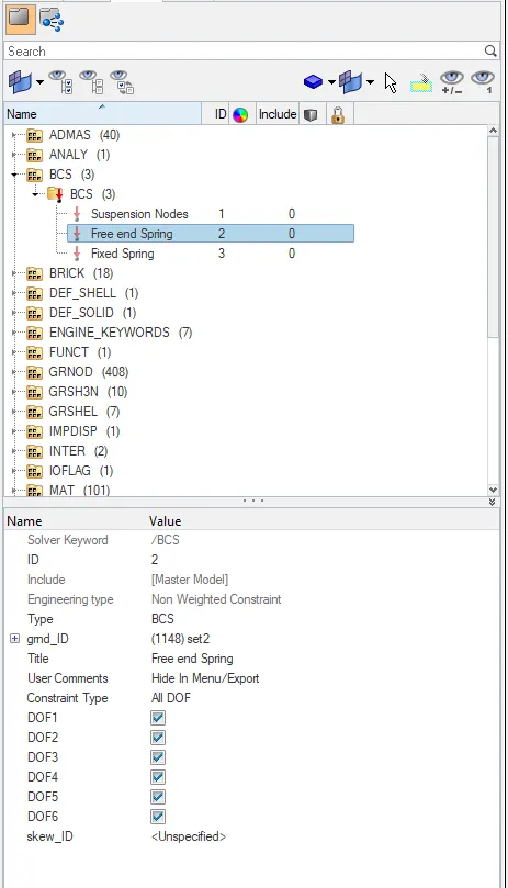
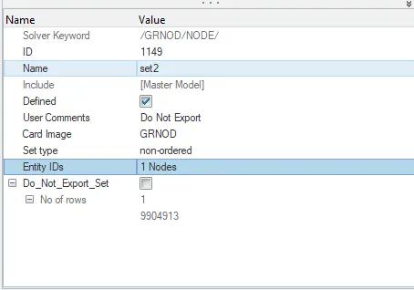
4. As the Node is in the free end It is locked in all Degrees of freedom to keep it As Fixed.
BC-3:
1. create a separate set and in the model area And in the Entity_ID define a Master Node in the Rigids of the Impactor.
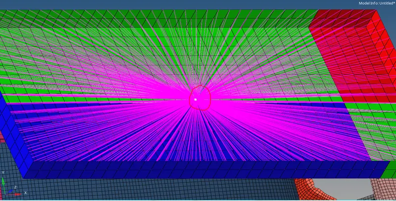
2. In the Solver area press Right click > Boundary conditions > BCS and name it as Fixed Spring.
3.In the grnd_ID select the Node set Created for the Fixed spring.
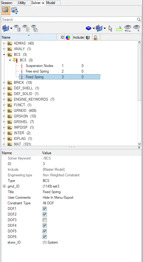
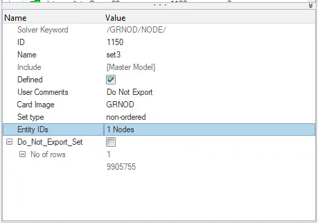
4. Skew system is assigned to this Master Node Set so the Z- direction is Set Free and all other degrees of Freedom are locked.
STEP-5 CREATION OF IMPOSED DISPLACEMENT:
1. Imposed displacement is Applied to the Impactor with a Specific Function.
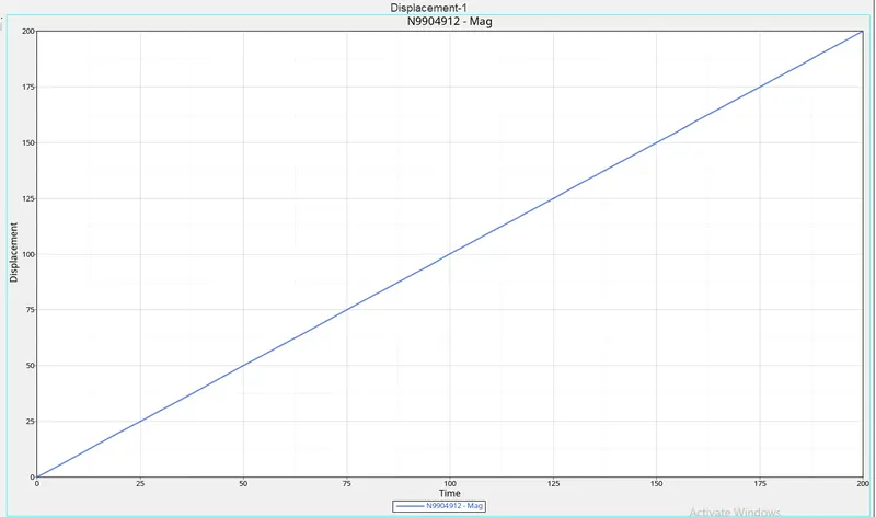
2. Impose the velocity of the impactor starting from 0 mm/s at t = 0. The displacement of the impactor should be 200 mm @ 200 ms.
3. To achieve this we need to define a function as input.
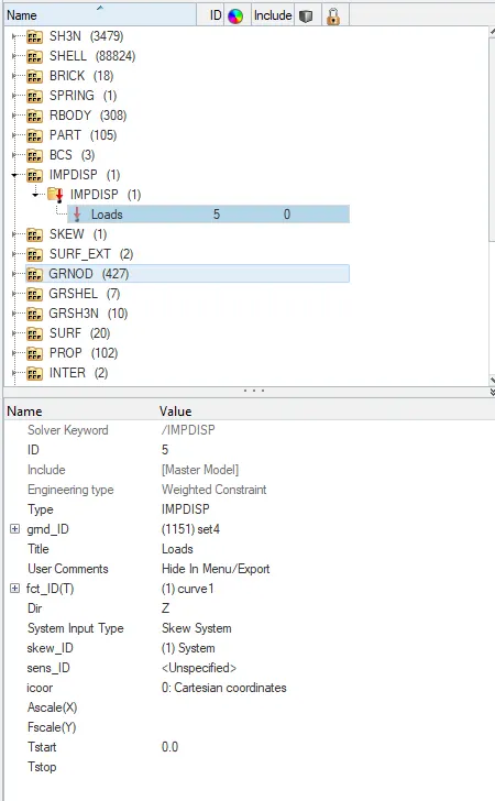
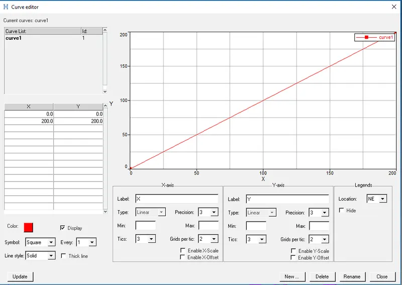
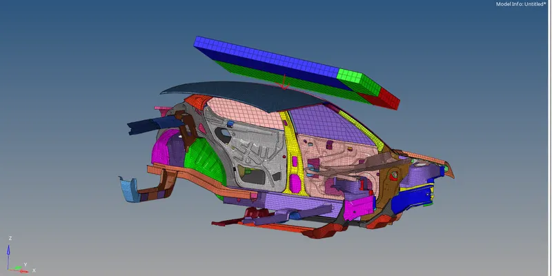
4. As per the Given Function the Imposed Displacement occurs on the Impactor on the Defined SKEW direction.
STEP-6 CHECK ENGINE CARDS:
1. Check for the cards requested,
- /ANALY card
- /DEF_SHELL card
- /DEF_SOLID card
- /IOFLAG card
- /SPMD card
- /TITLE card
The above-mentioned cards are verified in the cards section.
2. Some Engine cards which is necessary for the Running simulation are created.
ENG_ANIM_DT
Used to define No of Animation Steps.
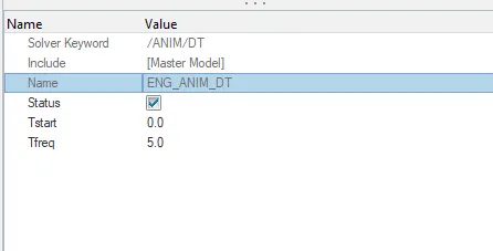
Creating an animation file every 5 ms
ENG_ANIM_ELEM
Elemental Outputs are acquired from this Card, the necessary outputs which needed to be viewed after the Simulation are Checked.
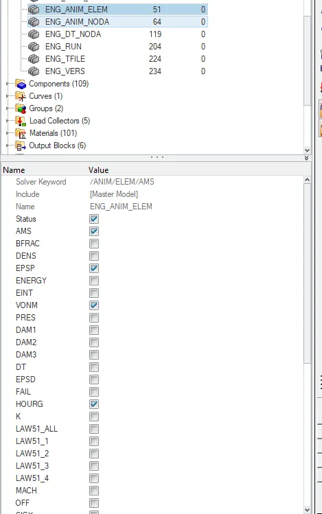
- Elemental Energy (Energy)
- Elemental equivalent plastic strain (EPSP)
- Elemental hourglass energy (HOURG)
- Elemental von Mises stress(VONM)
ENG_ANIM_NODA
To view the mass on the Nodes
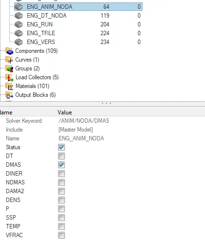
Nodal added mass(DMAS)
ENG_DT_NODA
This Card created to Input the Nodal Time step.
The constant nodal time step is selected
Tscale is the scaling factor for nodal time step 0.67, for Elemental it is 0.9
Tmin is the critical time step between node which is given as 0.0005ms
ENG_RUN
This Card Defines the Run time of the Simulation.
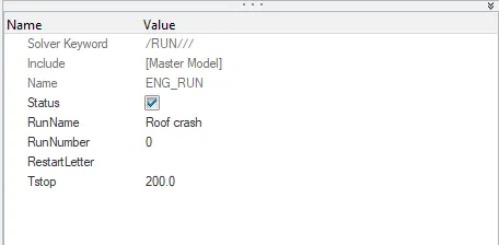
Tstop is given as 200ms.
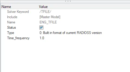
ENG_TFILE
This card Prints time history every 1 ms
STEP-7 OUTPUT REQUEST:
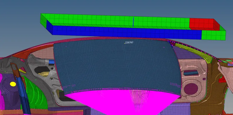
1.create a Node at the roof of the BIW to see the Displacement after the Impact.
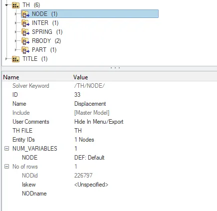
2. Time history should be created For the Output of the Displacement of the Node.
STEP-8 MODEL CHECKER:
1. After Applying all the boundary conditions and necessary Inputs, the model checker is performed Before running The simulation.
2. For Performing Model check go to Tools > Model check > Radioss block.
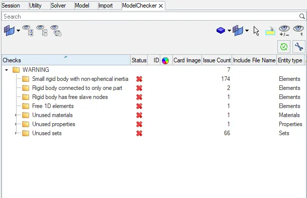
3.As there is No error the Model is good to Go for the SImulation.
RUN THE SIMULATION:
1. Click on the analysis panel in the Hypermesh.
2. Save the model in the local directory.
3. For Running The analysis: Analysis > Radioss is selected from the panel
4. The analysis runs and shows the result.
5. The energy error And mass errors are checked.
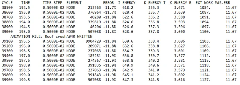
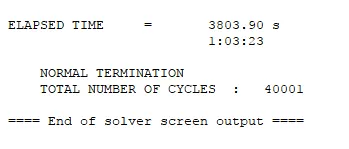
since the energy error is -11.9% which is less than 15% so it is acceptable, also the mass error is found out to be 11.67
Click on results to view the Simulation in h3d format.
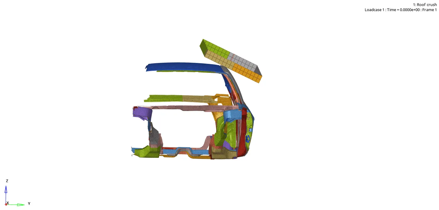
Here we can see some free parts moving, Even after all the necessary connections are made using Rigids.
Displacement Observation:
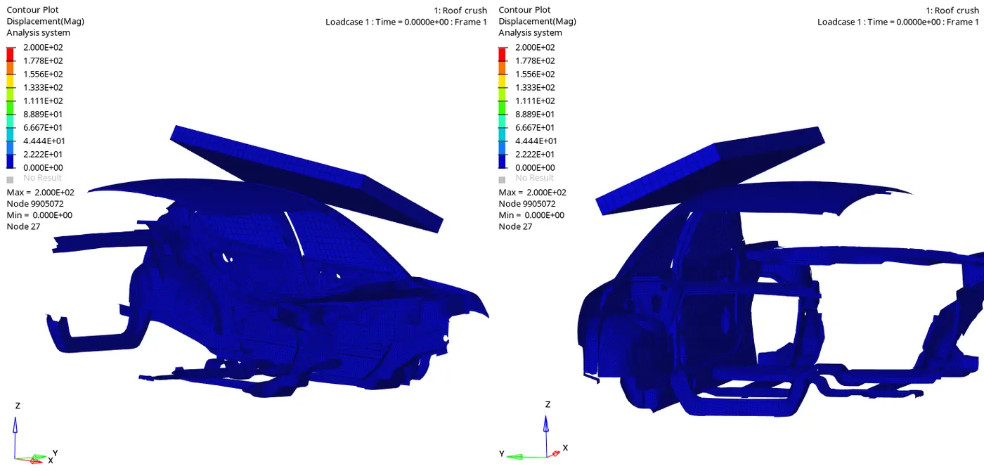
Maximum displacement: 2.000E+02 is at node 9905072
Minimum displacement: 0.000E+00 is at node 27
Von-mises Observation:
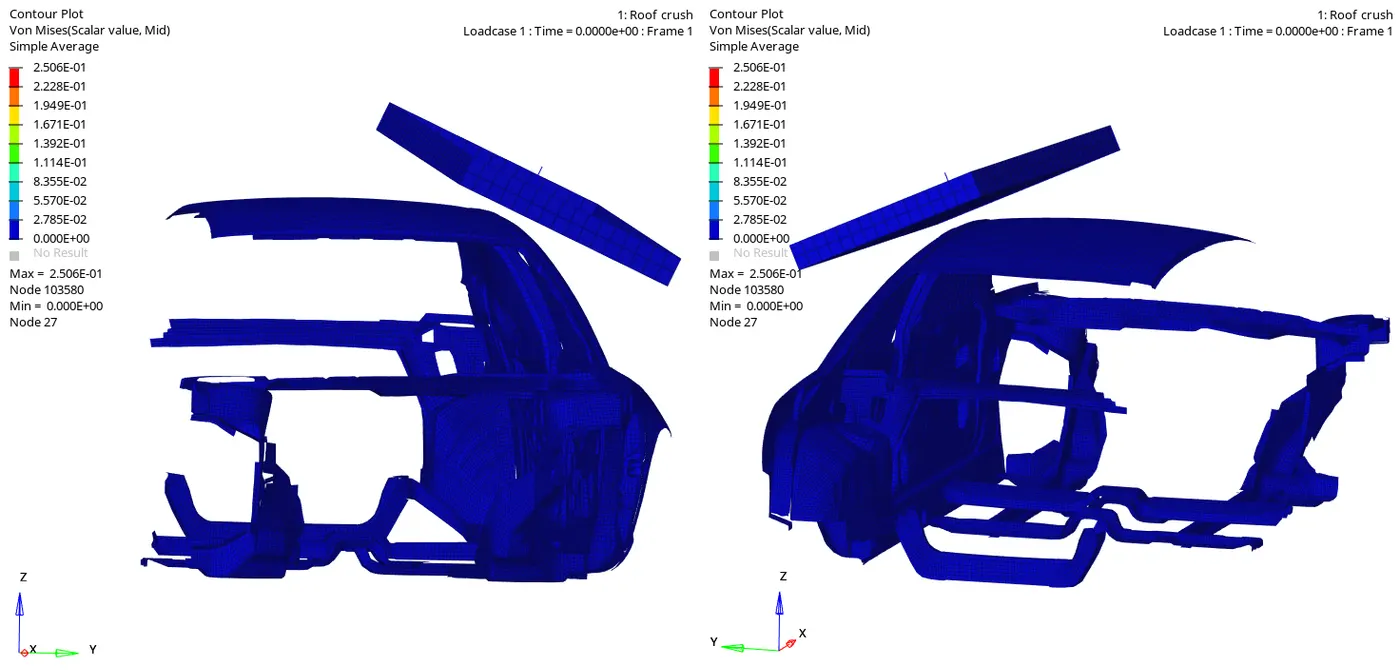
Maximum displacement: 2.506E-01 is at node 103580
Minimum displacement: 0.000E+00 is at node 27
FORCE Vs DISPLACEMENT PLOT:
1. To create a cross plot of Force Vs Displacement
- Select > Build plots > Load Case 1 > Displacement > Nodes > Select Centre node of Impactor

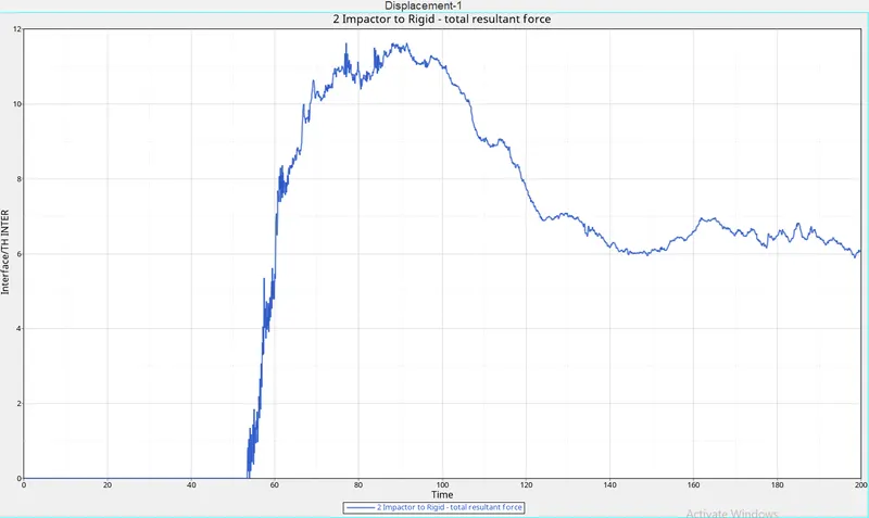
- Select Hypergraph 2D > Global Variables >Interface/TH INTER > Total rersultant force > Mag > apply
2. To cross-plot these 2 graphs as force vs Displacement, Go to file > Load > Preference File > Vehicle Safety Tool > Load > Math > 2Curves > Cross Plot.
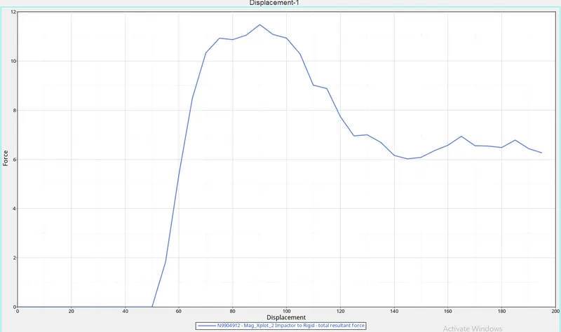
3.Select Curve x with holding shift key press displacement and holding on shift select the Curve Y as force and SELECT New Page and press Apply, to create cross plot data of Displacement Vs Force.
Observation From the Graph:
From the Graph, the Maximum resistive Force is 11.48KN at 90ms.

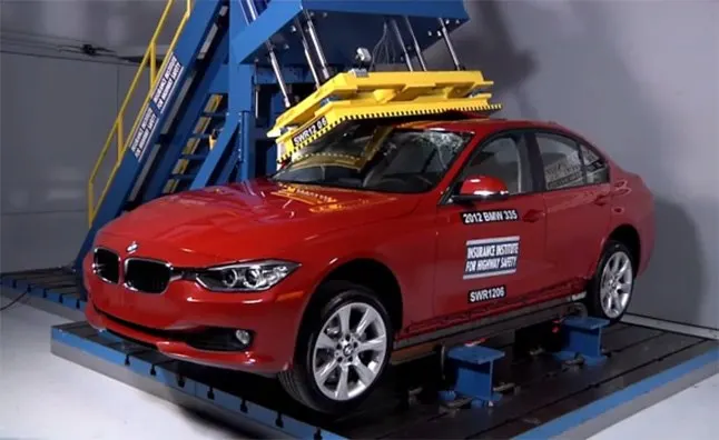
FMVSS 216 (Roof Resistance testing):
- Federal Motor Vehicle Safety Standards (FMVSS) is a U.S. federal vehicle regulation specifying design, construction, performance, and durability requirements for motor vehicles and regulated Automobile safety-related components, systems, and design features.
- FMVSS 216, Roof Crush Resistance, establishes strength requirements for the passenger compartment roof of passenger cars, multipurpose passenger vehicles, trucks, and buses with a GVWR of 2722 kilograms or less
1. According to the FMVSS216 the Specified Strength to the weight Ratio Required a resistance of Force 3 times the GVW ( Gross vehicle weight) to protect the passengers from the Roof Crash
2.Weight of The Body=174.8kg
3.Resistive Force=3*Weight of the Model* acceleration Due to Gravity.
4.R.F=5.14kN
5.The resistive force Obtained From The Graph is 11.48 KN.
6.From The result the resistive Force s greater than the Calculated Value. As the roof can withstand only 5.14KN.
7.So the analysis fails.
8.Due to the Students Version the results are Constrained, It may vary During Full Body analysis.
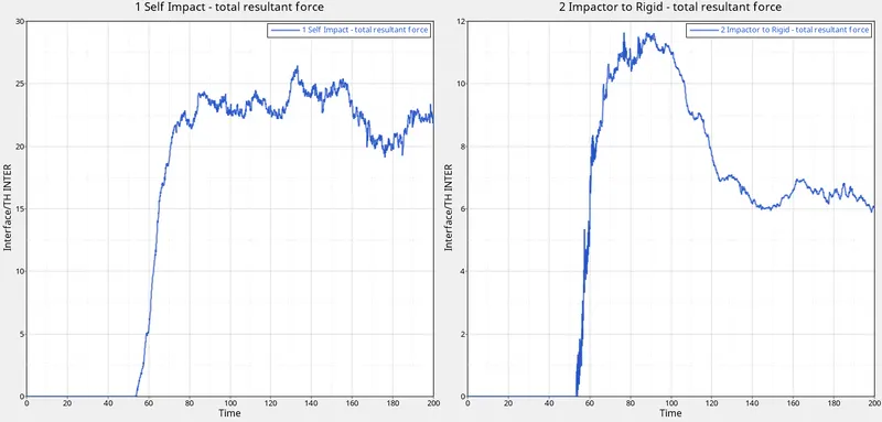
Interface Plot:
Energy Graph:
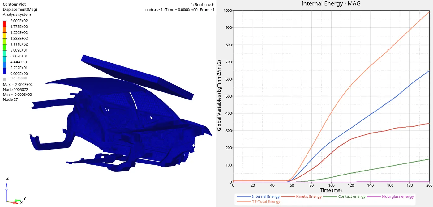
1. The Above Process is a Quasi-Static Analysis, i.e The process is Quite Linear and the Same as Implicit. The load here is Applied Slowly and the Structure starts to deform Slowly.
2. Initially The Kinetic Energy is Stable and Starts increasing At 60ms where the Impactor Starts Hitting the Roof of the body
3. The Internal Energy Starts where the Kinetic energy Started and From The graph, The Body possess a bit more Internal energy during Impact.
4. The Contact energy is started around 80ms where the Slave nodes come in contact with the Master Nodes.
Nodal Displacement.
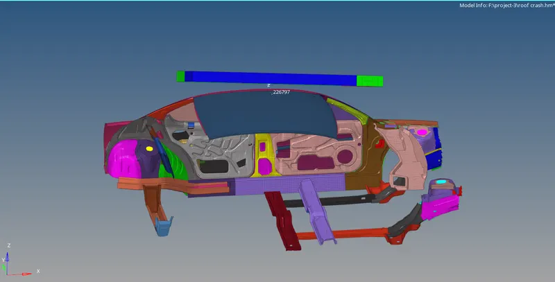
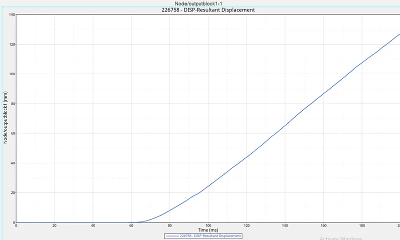
1. From the Graph the Node is stable and starts displacing around 60ms where the wall impact with The roof
2.The Node has been Displaced around 123m at 200ms.
CONCLUSION:
Performed Roof Crush analysis on the given model of the car and it can be seen from the results and graph observations that the given, BIW fails the Roof crush test however if the full car model is considered it may clear the FMVSS 216 target criteria.