Roof crash analysis on Dodge neon car BIW using FMVSS 214 standards
Objective
Perform the roof crash simulation on the neon car model.
In this simulation, we are going to put an impactor in the appropriate location. We are going to create the necessary contact between the car and the impactor. We have to change the boundary condition in the suspension tower and the impactor. We have to give the imposed displacement.
Introduction
BIW
Body-in-white (BiW) is the name given to a car body’s sheet when all its components—barring moving parts (e.g., hoods, fenders, etc.), trims (e.g., glass, seats, etc.), or chassis subassemblies—have been welded together. Usually, BiW constitutes about 27% of a car’s curb weight and remains the key determinant of how the car will perform.
ROOF Crash
The objective of a crash test is to measure how well a passenger vehicle would protect its occupants in the event of a serious real-world roof crash. Federal Motor Vehicle Safety Standard (FMVSS) No. 216 is the measure that gives us the valuers that how much it can be deformed so the passenger should not get injured that much. If it is within the limit then we can say that the car has passed the test otherwise it is failing.
FMVSS 216, Roof Crush Resistance, establishes strength requirements for the passenger compartment roof of passenger cars, multipurpose passenger vehicles, trucks, and buses with a GVWR of 2722 kilograms or less. The purpose of the standard is to reduce deaths and injuries due to the crushing of the roof into the passenger compartment in rollover accidents.
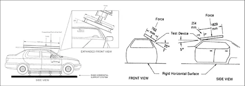
The prescribed static loading device is a rigid unyielding rectangular block 762 millimeters by 1,829 millimeters. It shall not move more than 127 millimeters to achieve the specified resistive load when applied to the forward edge of a vehicle’s roof.
The resistive load to be achieved is 1½ times the unloaded vehicle weight (UVW) of the test vehicle or 22,240 Newtons, whichever is less. Both the left and right front portions of the vehicle's roof structure shall be capable of meeting the requirements. The passenger car's sills shall be placed on a rigid horizontal surface and fixed rigidly in position. The vehicle's windows shall be closed and the doors shall be locked.
Procedure
1. We are going to choose the profile to be Radioss.
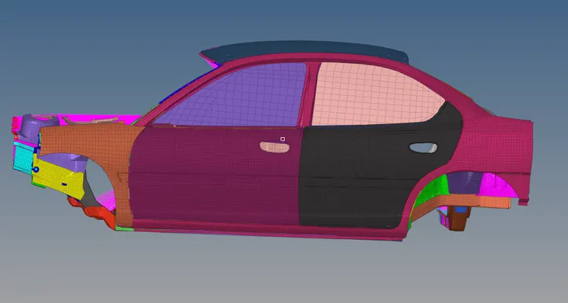
2. Now we are going to import the model. We have to import the car model and impactor both.
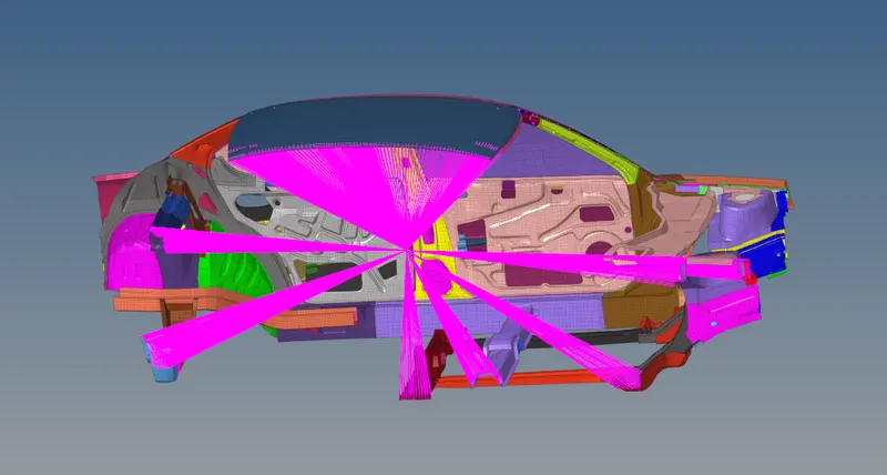
Impactor:-
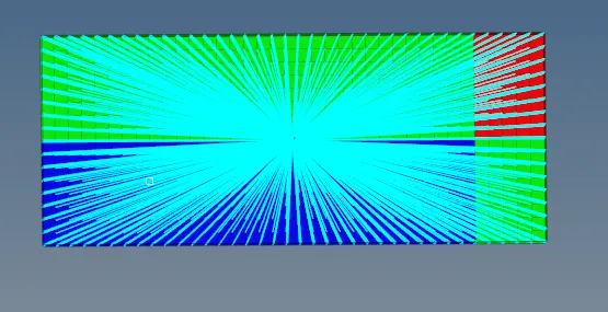
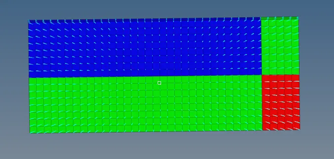
Car and impactor
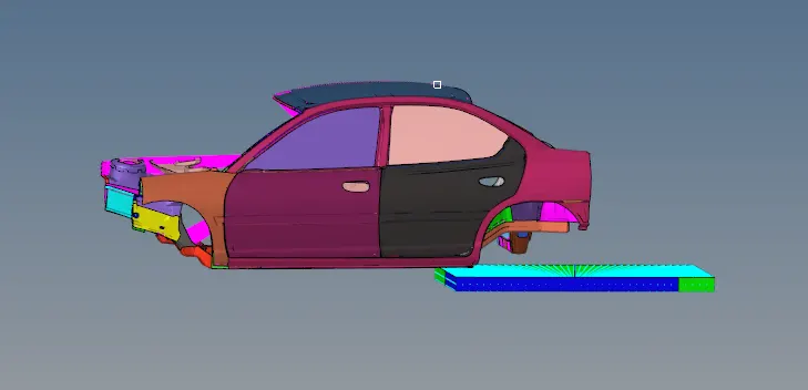
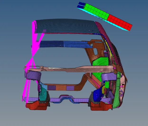
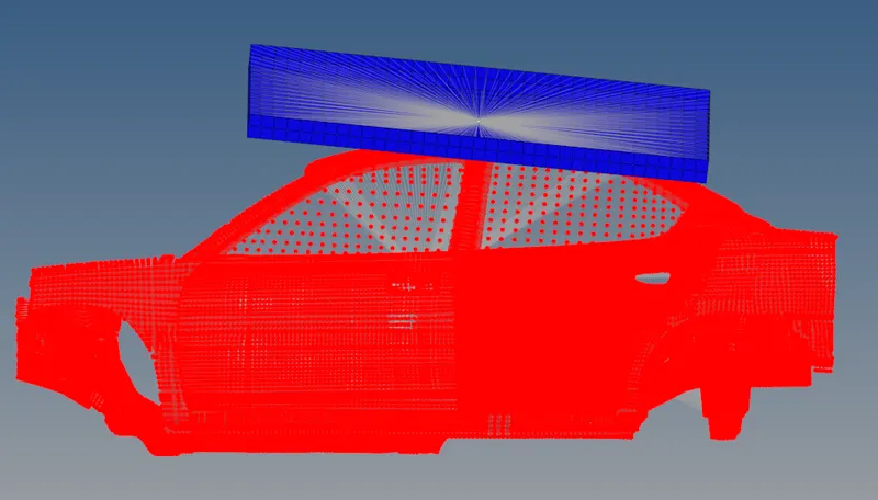
3. Now we have to displace the impactor at the appropriate region. In order to that, we have to follow the instruction which has been given in the challenge.
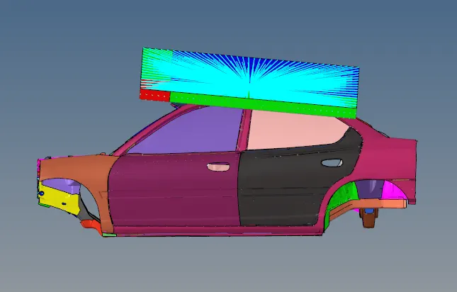
First, we are going to give a 180° rotation about the global z-axis with the point opposite to C as the base point. Then we are going to give a 5° rotation about the axis through axis AB and a 25° rotation about the axis through axis AC.
After following these commands properly, we will get the impactor at the desired location as shown below:
4. Now we are going to check the unit of the model. For that, we will go to the BEGIN_CARD.
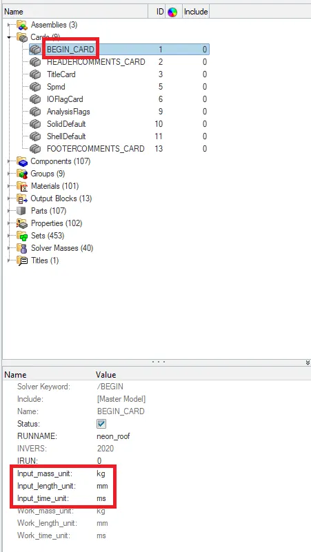
So the unit of the system is in kg, mm, ms.
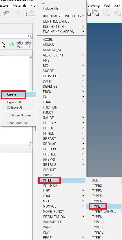
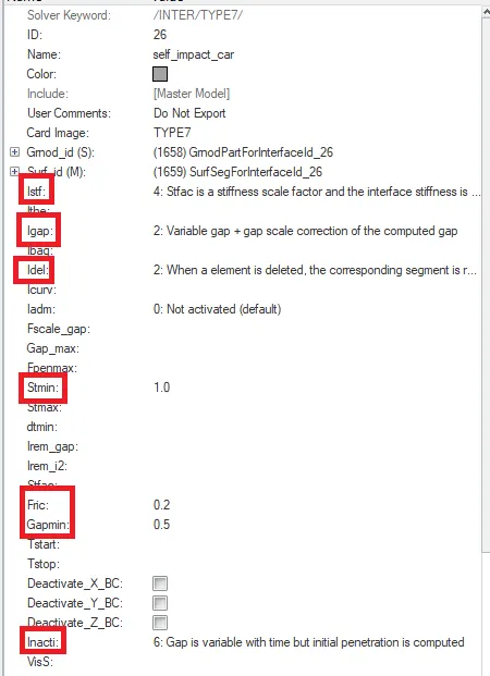
5. Now we are going to give the model a type 7 self contact. To create the contact we will go to the solver and we are going to create it.
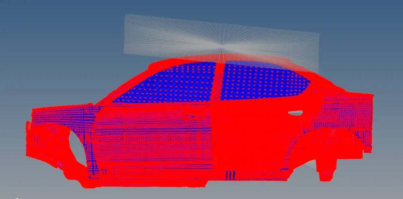
In the contact, we are going to give the master and slave nodes. It is a self contact so we are going to take the master and slave nodes to be all nodes of the car model.
We are going to give the recommended value to the interface.
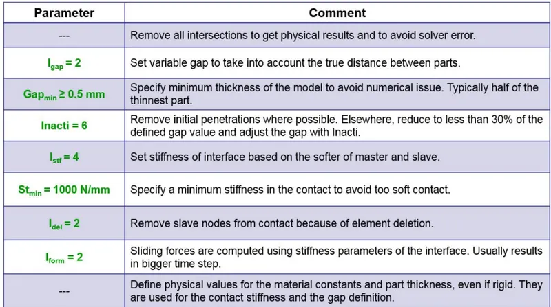
We are going to take the friction to be 0.2 because it is given in the problem so instead of the recommended value we are going to give friction to be 0.2.
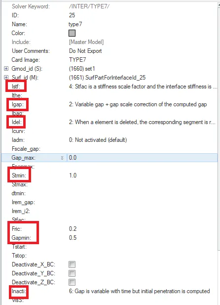
6. Now we are going to give the type 7 contact between car and impactor. In this contact, we are going to take the impactor to be a slave and a car to be our master.
We are going to give the recommended value to the interface.
7. Now we are going to check the connectivity of the model. We don't want any component of the model to be free. Because if there is any free component that remains on the model after the crash they will go fly away. That is bad for our simulation. We want the components to be connected for better results.
So to give the connection we will go to the 1D--> rigids


After we select two or more nodes, those two components will be connected by an RBE2 (Rigid Body Element) that will hold those components in place. An RBE2 element has infinite stiffness, it will not deform under excessive loads.
8. Now we have to create some boundary conditions for the suspension shock tower. We need to constraint the z-axis for the suspension tower.
To create the boundary condition we have to go to the solver and right-click on the tree then go to the create--> Boundary Condition--> BCS
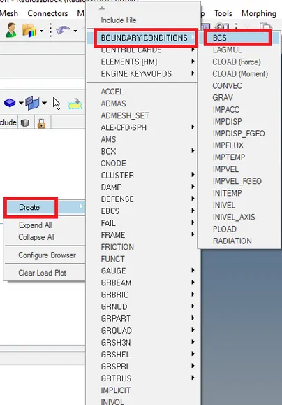
Then we are going to constraint the z-direction for the suspension tower.
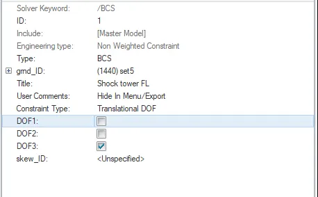
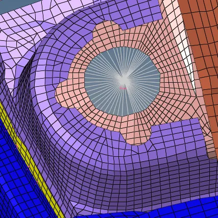
So we have to create 3 boundary conditions for the three suspension towers separately.
9. Now we are going to give the boundary condition to the free end of the spring. The spring is in the impactor's assembly. We are going to constraint all DOF of the spring.
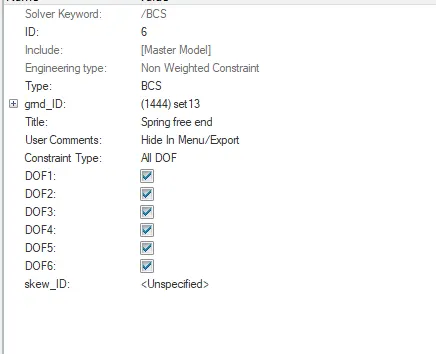
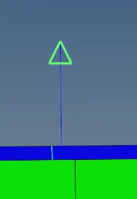
10. Now we have to create the boundary condition for the master node of the impactor. We want the impactor to move only in the direction of perpendicular to the impactor. So in order to give the boundary condition to the master node. We need to create the skew.
We are going to create the skew in the middle of the impactor. So for that first, we are going to create a temp node there and after that, we are going to create the skew at that node. SO to create the skew we will go the create--> Skew--> Mov
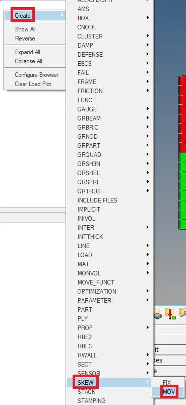
To create the skew we are going to select the option "create by node reference" and we are going to define the x-axis and XY-plane.

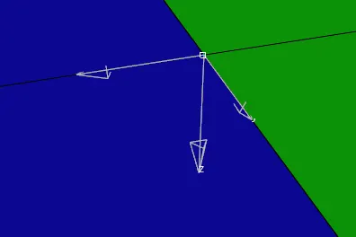
So now we are going to give the boundary condition to the master node of the impactor.

We have constraint all DOF apart from the z-axis and we have selected the skew in the skew ID.
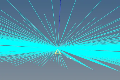
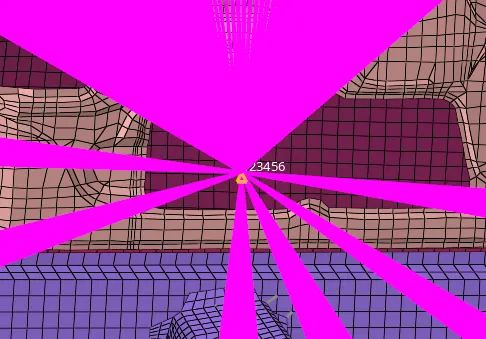
11. Now we are going to give the boundary condition to the master rigid node. We are going to constraint all the DOF of the node.
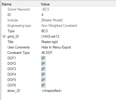
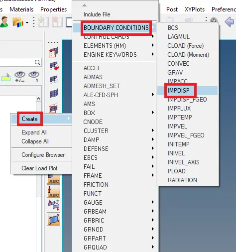
12. Now we have to give the imposed displacement to the impactor. So to give the imposed displacement to the impactor. We are going to create the boundary condition. So to create the boundary condition we have to right-click on the tree and use the option of create--> Boundary Condition--> IMDISP
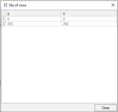
Now we have to create the curve to assign that as they have asked. So we want to impose the velocity of the impactor starting from 0 mm/s at t = 0 and the displacement of the impactor should be 200 mm at 200 ms.
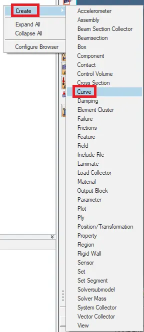
So we are going to create the curve. To create the curve we will go to the model--> create--> curve
In the curve, we are going to data to create the curve.
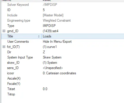
Now we are going to assign the curve and skew in the imposed boundary condition. We are going to give the direction to be z-axis. To imposed displacement, we are going to select the impactor master node.
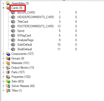
13. Now we are going to create the missing cards. So to create the control cards we will go to the Analysis--> control cards

So in the beginning there were only 9 cards present in the model.
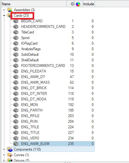
So after creating the necessary cards in the end we get 23 cards in the model.
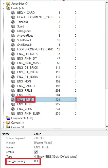
14. We want the print time history file to be 0.0001 s. So in order to that, we will go to the ENG_TFILE card.
15. We want the simulation to be run for 200 ms. So in order to do that we will go to the ENG_RUN card.

16. We want to create an animation file for every 0.005 s. So in order to change that we will go to the ENG_ANIM_DT card.
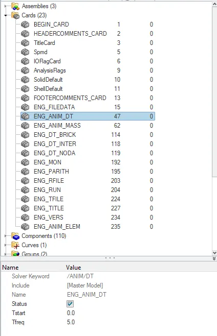
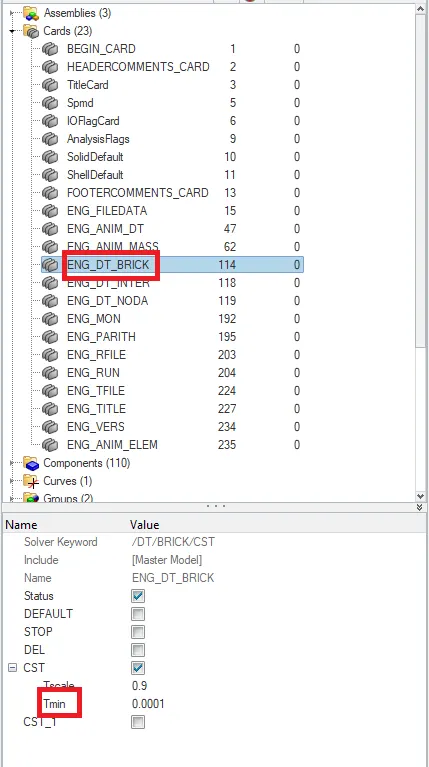
17. Now we are going to give the time step for the simulation. We need to give the time step value in brick to be 0.0001 ms.
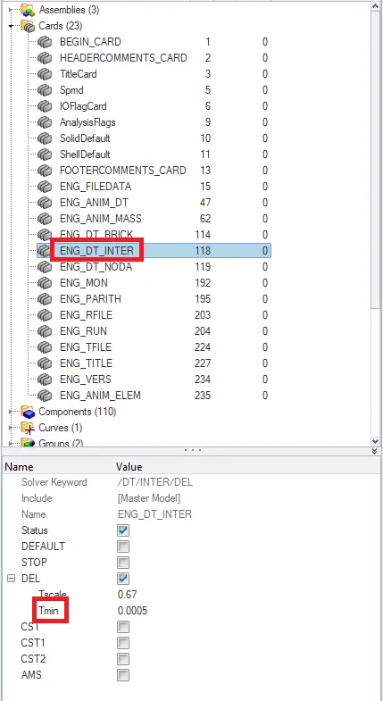
In inter to be 0.0005 ms.
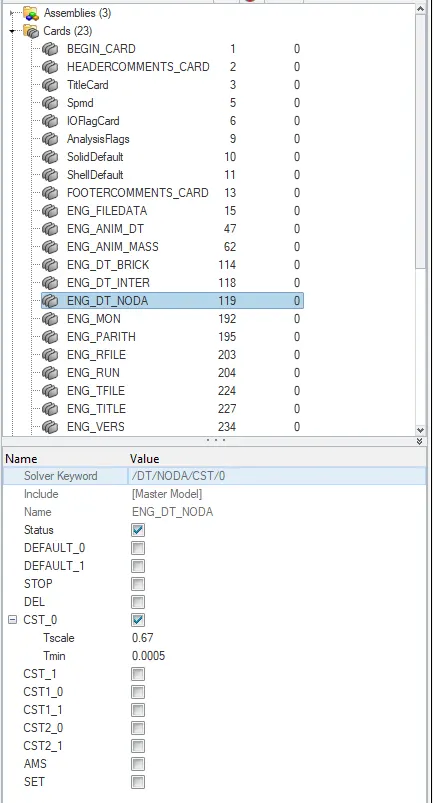
And in the Noda to be 0.0005 ms.
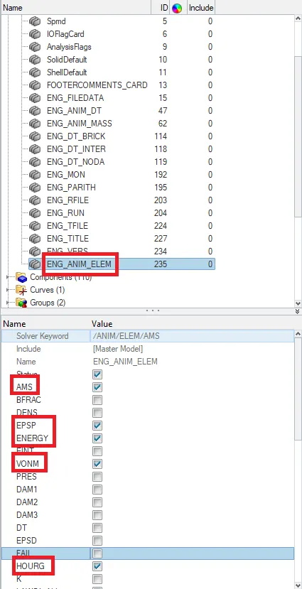
18. Now we are going to include elemental energy, equivalent plastic strain, hourglass energy, von mises stress. So in order to that we have to go to the ENG_ANIM_ELEM
19. Now we are going to request the time history file to get the required output. So to create a time history file we will go to create--> TH
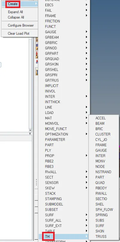
So we are going to create all the required TH files.
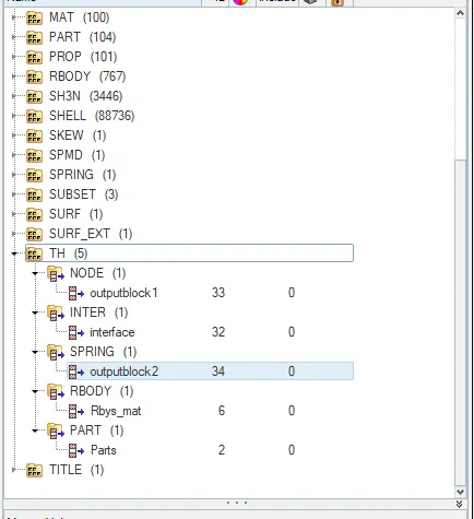
20. Now we are going to check the connectivity of the model. We don't want any component of the model to be free. Because if there is any free component that remains on the model after the crash they will go fly away. That is bad for our simulation. We want the components to be connected for better results.
So to give the connection we will go to the 1D--> rigids
After we select two or more nodes, those two components will be connected by an RBE2 (Rigid Body Element) that will hold those components in place. An RBE2 element has infinite stiffness, it will not deform under excessive loads.
21. Now we are going to run the simulation. To run the simulation we will go to the Analysis-->Radioss


Now we are going to analyze the simulation and we are going to plot the required graph.
22. To check the simulation we have done is correct or not we are going to check the energy error and mass error. If it is in the accepted range then we can say that our simulation is correct.
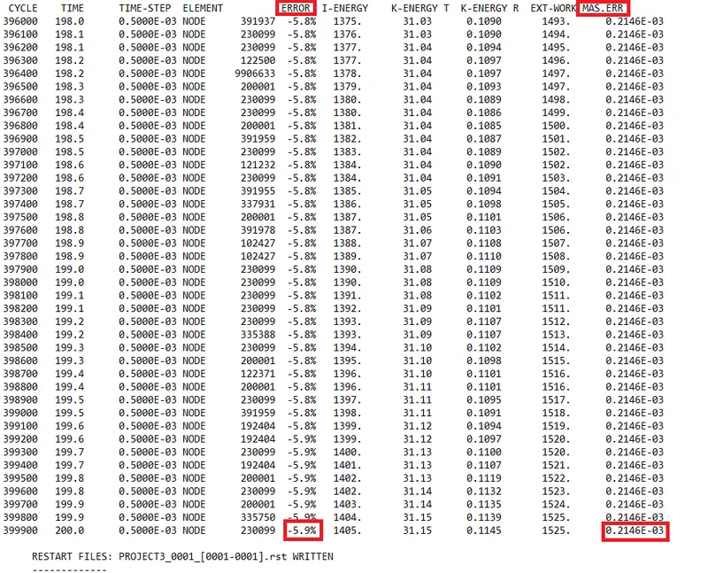
The energy error is between -15% to 5% and the mass error is 0. That is very less so we can see that the simulation we have done is right.
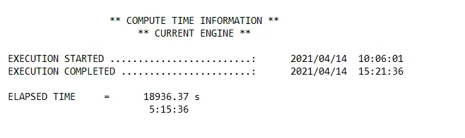
The total running time of the simulation was 18936.37 seconds.
23. Now we have to analyze the simulation frame by frame and check the behavior of the element after the impact.
Output
Simulation Gif
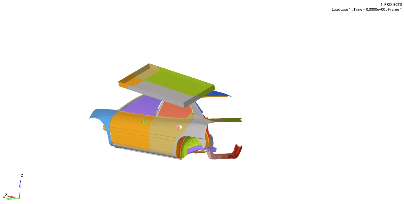
From the simulation, we can see that the impactor is moving with the imposed displacement and collide with the car model. After the collision elements are starting to get deformed. The elements which are on the roof of the model get deformed first. After that load gets transferred to the rest of the model and elements start to get deformed. Deformation of the elements depends upon how much the load is transferring to the elements.
Displacement Gif
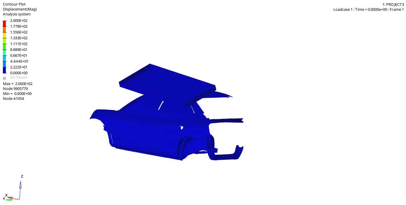
In this Gif, we can see that how many elements how much getting displaced. We can see that the elements which are on the roof get displaced more because the collision is taking place on the roof.
Von Mises Gif
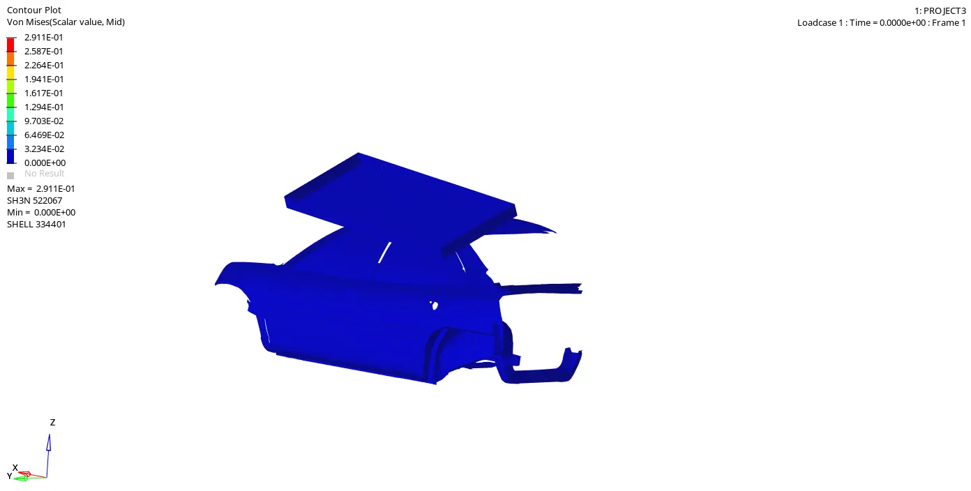
Von Mises stress is a value used to determine if a given material will yield or fracture. It is mostly used for ductile materials, such as metals. The von Mises yield criterion states that if the von Mises stress of a material under load is equal or greater than the yield limit of the same material under simple tension then the material will yield.
Hourglass Gif
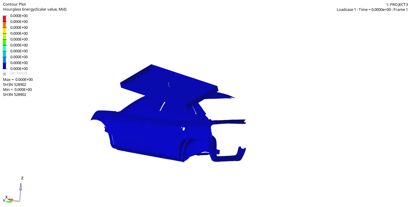
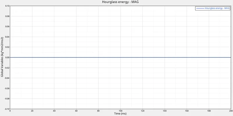
We have taken the shell element to be QEPH so we get hourglass energy to be zero.
Plastic Strain Gif
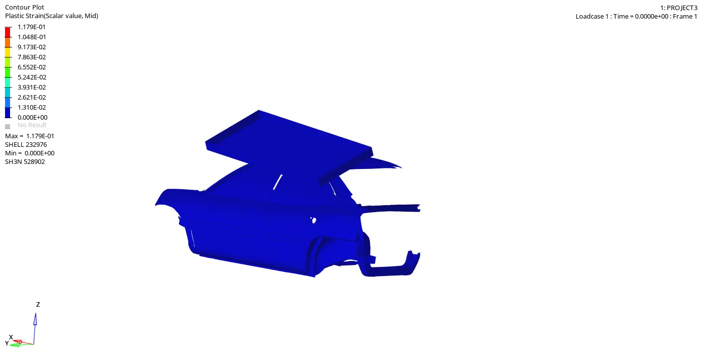
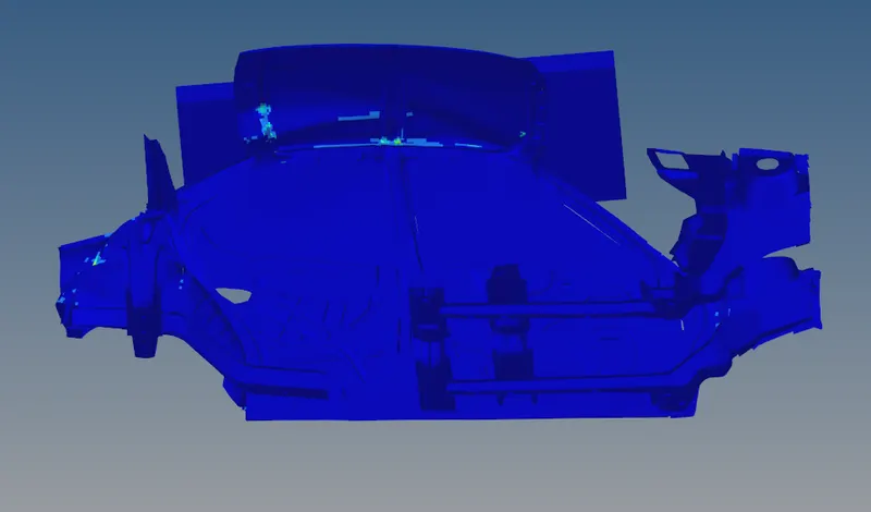
We can see in this gif that the elements are deformed but there is no plastic strain. The reason for that is that we are doing the quasi-static analysis.
Quasi-Static, quasi-equilibrium, from the Latin quasi, meaning 'as if' and static means stable. So in this case the load varies with time but it is so small which is negligible. When the body is loaded slowly its deformation rate is also very slow.
So deformation is very small. The deformation in most of the elements is within the elastic limit. So the plastic deformation is happening in very less no. of elements and it is very less.
Elemental Energy Gif
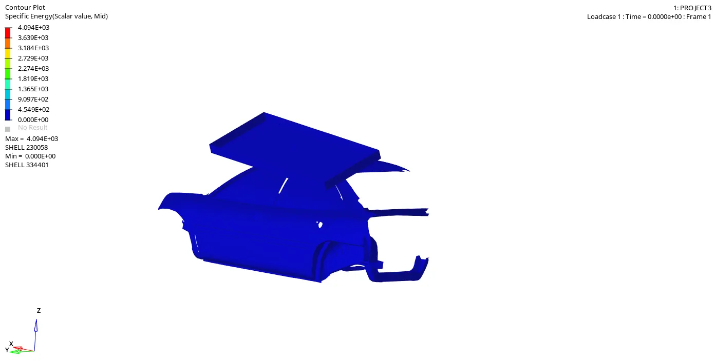
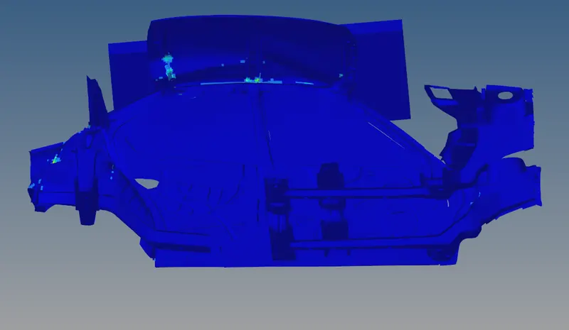
In this GIF we can see the energy transfer to the elements. The energy transfer is recorded after the elements get into the plastic region. Because very few of the elements are going into the plastic region and plastic strain is very less. So that we are not getting much of the elemental energy.
We can see that where we are getting plastic strain there only we are getting elemental energy.
Energies
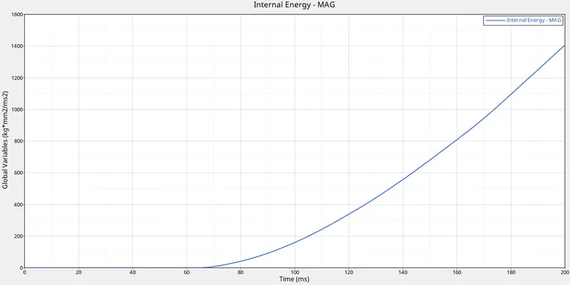
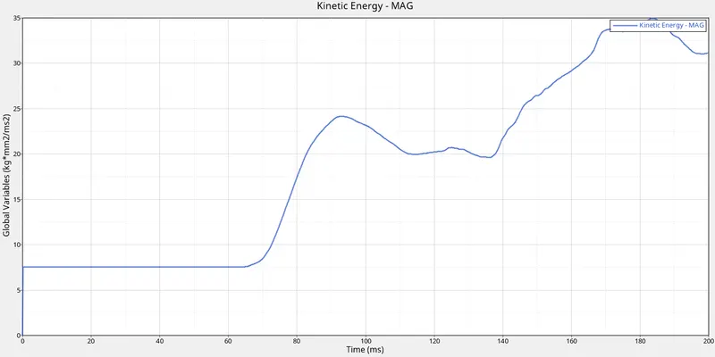
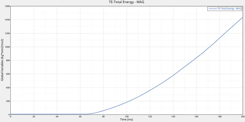
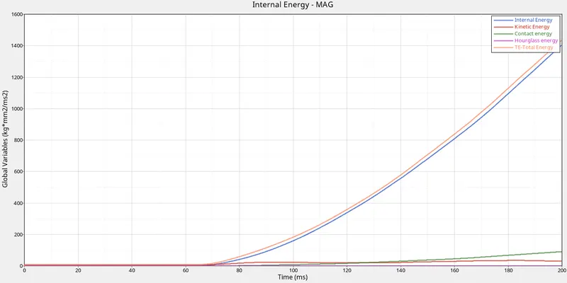
From the above graph, we can see that with the time, In the starting the impactor is moving, it has some velocity. So because of that, there will be kinetic energy. When the impactor gets collides with the model the energy will transfer to the model and the kinetic energy of the model gets increases. After some time it will decrease for a small time period and then again the kinetic energy will increase.
In the above graphs, we can see that after the collision the energy will transfer to the car model and it will increase with respect to time till the end of the simulation.
The total energy is the sum of the kinetic energy and the internal energy. So because of some contact energy, the total energy is decreasing at the end of the simulation.
Contact Energy is the energy due to contact between two elements. So when the deformation occurs elements start to get in contact with each other so due to contact between elements we get the contact energy. We are getting very low contact energy in the simulation.
We have taken the shell element to be QEPH so we get hourglass energy to be zero.
Force vs Displacement
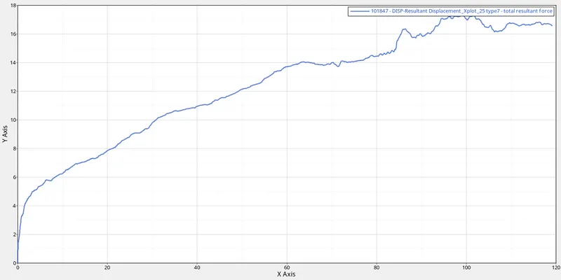
The above graph is between Force (Y-axis) and Displacement (X-axis). We are storing the values at node 101847 which is just above the B-pillar. So we are going to plot the graph between force and displacement at that point. We can see from the graph that with an increase in the displacement, forces are also increasing at that node.
FMVSS 216 target load:-
We can see that the maximum Force that we get is 17.33 kN at around 99.09 mm displacement of the master node of the Rigid body of the Impactor in the simulation.
To check if the FMVSS 216 target load of 47,000 N (= 3 * GVW) has been met, we must know the Gross Vehicle Weight (GVW) of our model. In our case, it is 174.05kg. Since it's a student version we'll refer weight of the Whole actual vehicle weight (1600Kg).
To now convert this into weight, we must multiply it by 9.81, then we get 11,934.35N. And, as a Factor of Safety, we multiply this value by 3 and get the Target load as 47,088N.
Since our value 17.33kN is lesser than the specified value of 47,000N, we can conclude that this condition has been satisfied and met properly.
Learning Outcome
Learn about the roof crash test.
Learn about the FMVSS 216.
Learn how to plot a cross graph in Hypermesh.
Learn about internal energy, kinetic energy, hourglass energy.