Roof challenge
Objectives:
- For the given roof styling, develop the essesntial flanges and reinforcements, provide appropriate dimensions and check for draft analysis and to perform roof curvature study using NX-CAD Introduction.
- Provide appropriate dimensions and check for Draft analysis.
- Do a curvature study on the roof and perform calculations to determine the position of the Bow-roofs.
-
Suggest and implement remedies in the design if the criterion is not full-filling
Introduction :
Start with the creation of a roof ditch area with a tool opening angle of 7 degrees. Develop the reinforcements as separate parts.
Roof :
An automobile roof or car top is the portion of an automobile that sits above the passenger compartment, protecting the vehicle occupants from sun, wind, rain, and other external elements.
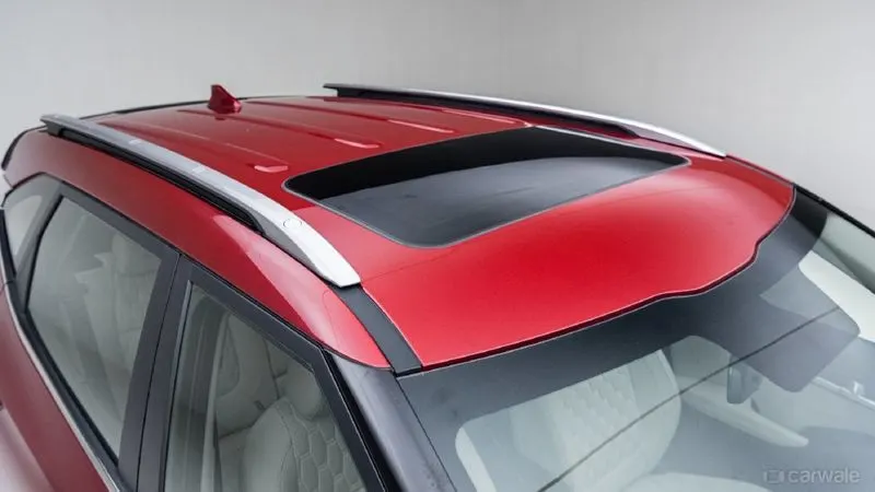
The roof is a styling surface part which is fixed with the BIW body through the rails and panels inside the upper roof to provide it strength and stiffness.
Ditch area plays an important role here to fix the reinforcement on the component.
The rails and reinforcements are joined to the ditch area with a spot weld where it's not the styling part.
The required tool opening angle is minimum 3 Degrees..
Types of Roofs
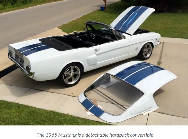
1. Hardtops: These are common rigid automobile roofs normally seen in most of the cars which are either made of metal or plastics. The different type of these roofs that are used in Convertibles are mentioned below
- Detachable Hardtops: This type of hardtop is manually removed from the roof and then stored usually in the trunk. They are also made from metal or plastic.
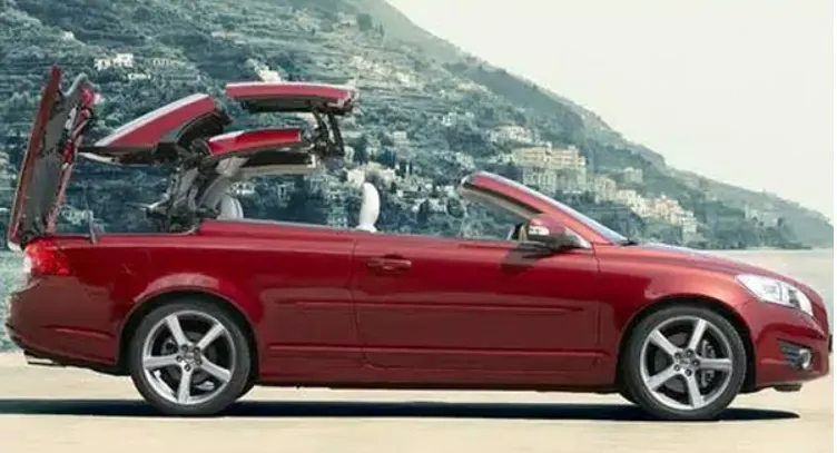
- Retraceable Hardtops: Made from metal or plastic and is retracted automatically.
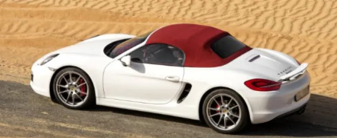
- Soft tops: This type of convertibles has roofs that are not made from metal or plastic. They are made of textile. The earliest versions of the convertible used canvas for the roofs. More recent models use cloth materials instead. Other materials used now include latex, vinyl, polyvinyl chloride. When the roof is folded, it is called a stack.
Factors which is considered before creating Ditch area,
- Headroom clearance
- Visibility criteria
- Back door assembly
- Windshield assembly
- Material Selection
Material selection plays an important part in designing any part. The material for a part is selected keeping in mind the tensile strength, bending, static and dynamic loading that the part would be subjected to. Materials used for the roof and its different reinforcements are mentioned below.
- Roof: SP121AQ T0.7
- Front Roof Rail: SP783AJQ
- Rear Roof Rail: SP783AJQ
- Bow Roofs: SP121BQ
- Centre Roof: SP153-98OPQ
- Visibility Criteria
The visibility criteria of a driver is one of the most important factors when designing the roof. The roof should be designed such that it does not hinder the visibility range of the driver. The ditch area of the roof is design keeping this criterion in mind.
- Head Clearance
This factor is considered when designing the reinforcements of the roof. The reinforcements should be designed in a way that it provides ample headroom clearance for the occupants in the car and does not collide with the head in case the car moves over a bump It should not act as a hindrance for the driver’s rear visibility.
- Position of the reinforcements
The position of the reinforcements are governed by the below to criteria’s.
- Heat distortion
This determines the temperature the roof structure can withstand. The value obtained from the heat distortion prediction formula should be less than 2.7 to be deemed fit for use.
- Snow load criteria
This factor is taken into consideration for area with high snowfall which then sets on the car roof. This criterion measures the elasticity of the roof wherein the roof should come back to its original shape and from on the removal of the snow, which in this case acts as the load. The value Qr obtained for the snow load prediction formula should be greater than 3.1 for the design to quality for being used.
- Drawibility
The roof and its parts are manufactured using deep drawing process. For this reason, the designs should be manufactural and the design should have a positive draft angle for smooth surface build and also reduced induced stresses in various parts of the reinforcements.
Input Data
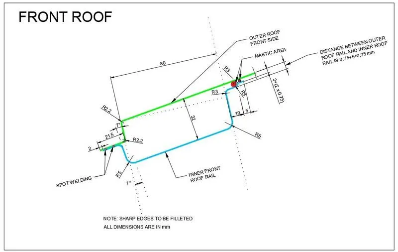
Front Roof Rail Master section
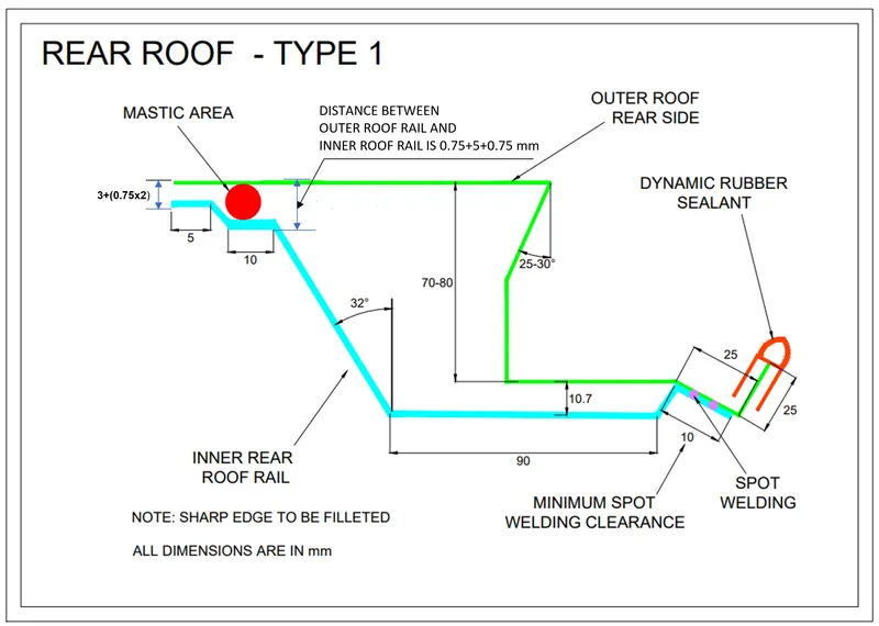
Master section of the Rear Roof Rail
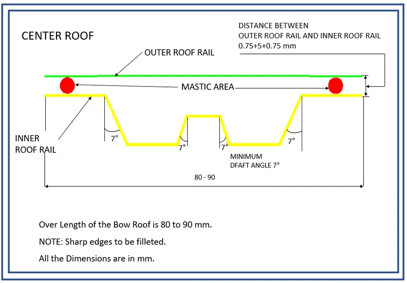
Master section of Center Reinforcement Rail
Design of components of Roof
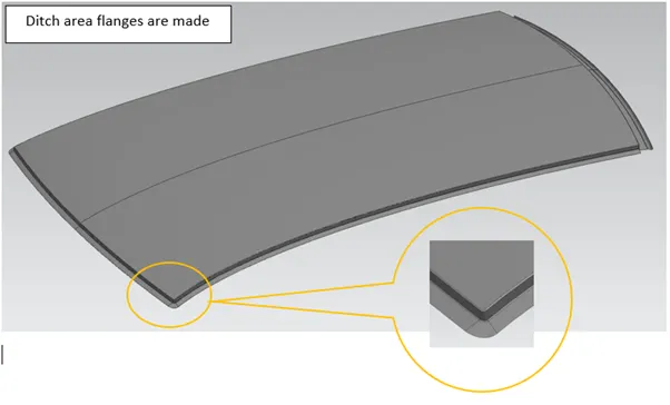
- Design of ditch area flange
We will start first by extracting surface from input data solid roof part. Using this surface we design ditch area flanges
- Design of front roof rail
For designing front roof rail we need to consider some parameter which are as discussed below
a. Visibility of the driver and passenger
We always keep in mind while designing the front roof we do not reduce the visibility available to driver. While designing front roof one must stick to the master section dimensions because little change in dimension will have impact on the visibility of the driver (e.g. small change in angular dimension will lead to large change in linear dimension)
- Design of Rear roof rail
Rear roof rail is also designed same as front roof rail
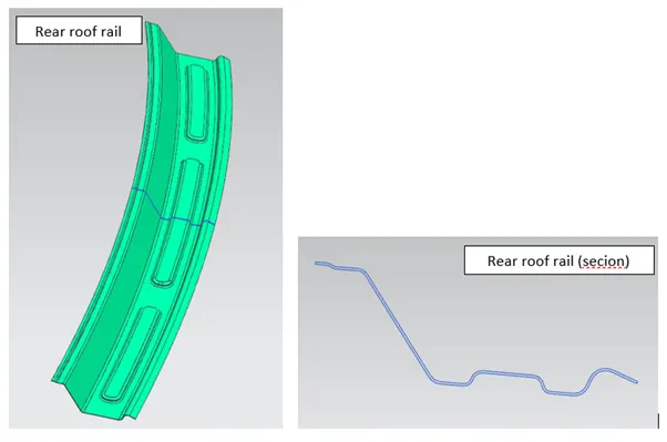
Material- SP783AJQ
Thickness- 0.75
Made from body side outer scrap
- Design of entre roof rail
Following same design process as front roof rail and master section we design centre roof rail
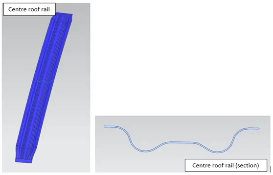
Material- SP153-980PQ
Thickness- 0.75
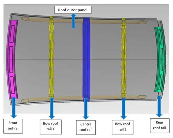
- Design of Bow roof rail (1 & 2)
Bow roof is sheet metal component which is used to add more structural strength to the roof. On the basis of the curvature of the roof bow roof is provided.
To justify the position of the bow roof there are two criteria are used-
a. Heat distortion criteria
b. Snow load criteria
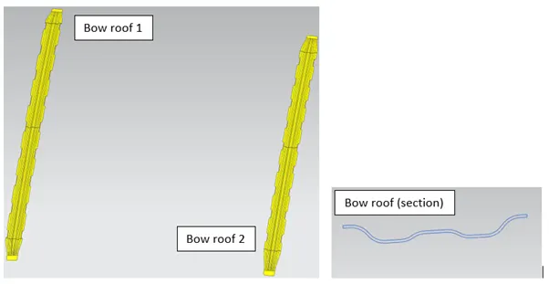
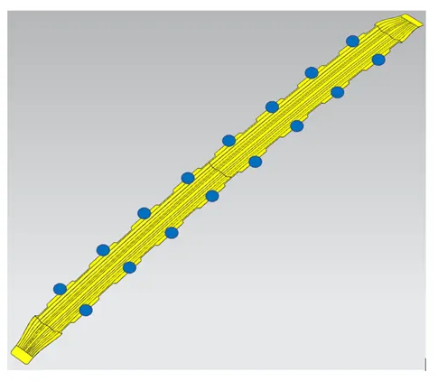
Bow roof is joined with the help of mastic sealant. Points are highlighted where mastic sealant will be applied
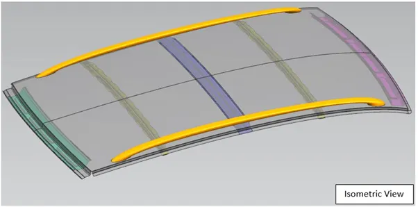
Assembly View of Roof
Bow roof rail calculations
- Heat Distortion calculations
W = [1.73 x 10^(-3) x L] + [1.85 x 10^(-8) x (R^2)/t] + [ 1.10x10^(-3) x l] - 2.68
Judgement Condition : OK< 2.7> 3.1
Where
L = Roof Length in X-Direction[mm](Roof dimension in 0-Y)
R = Roof curvature
R = 2(Rx*Ry)/(Rx+Ry)
Rx = X curvature
Ry = Y curvature
t = Roof plate thickness [mm]
l = Bow Roof Span [mm]
Procedure to measure the parameters-
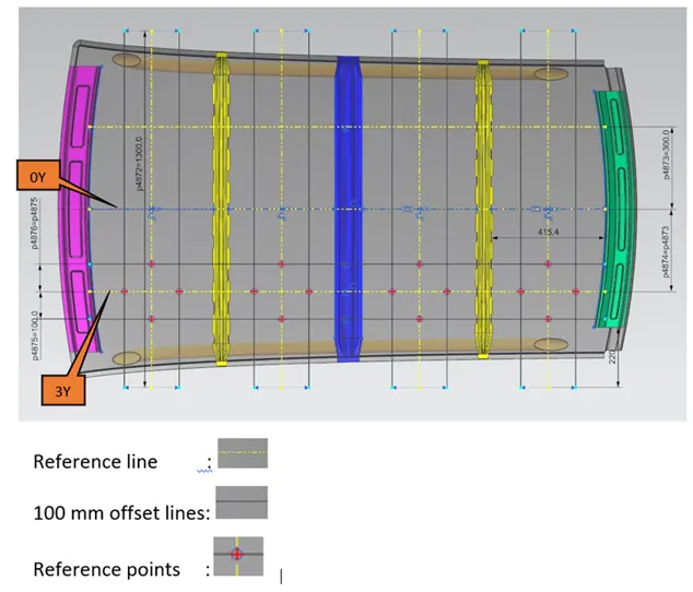
a. On plane parallel to the top plane draw sketch in which 0Y line is offset by 300 mm (3Y) on both the sides of 0Y line.
b. Draw lines perpendicular to 0Y line passing through point exact midpoint of the two adjacent parts (e.g. midpoint between front rail and bow roof 1)
c. Offset these reference lines on both sides by 100 mm
d. Mark intersection points (red points) of reference line (Yellow lines) and 100 mm offset lines(Black lines)

Snow load criteria calculations
Snow load criteria is useful to justify the bow roof rail position in snow fall regions. Due to snow fall snow will get collected on the top roof which will tend to bend the roof. Bow roof will be at such position which will provide more strength to roof against bending.
Qr = [Iy x t2] / [α x s x [(Rx + Ry)/2]2 x 10-8]
Note: The Qr value given over here is correct. There was a typo error in the formula given in the video.
Where
α = My x Lx2 x 10-12 , My = Y(Ly-Y)
Judgement condition = Qr ≥ 3.1
250 ≤ s ≤ 380
t = Roof plate thickness [mm]
Ly = Distance between the front and rear roof Rails on the Vehicle along with 0Y[mm]
Length of Roof panel with the center point between Roof rail Front /Rear as the reference point of the front and the rear.
Lx = Distance between the Left and Right end of the roof on the Roof BOW [mm]
Width of the roof panel exposed on the surface.
Y = Distance front Front Roof Rail to Roof BOW[mm]
s = Distance for which Roof BOW bears divided load [mm]
s = L1/2 + L2/2
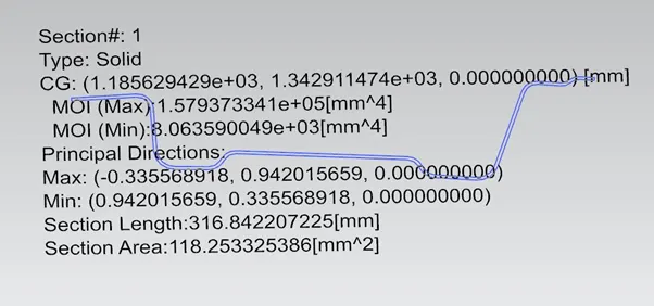
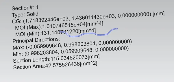
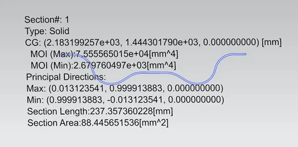
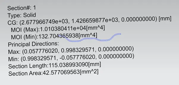
Iy = Geometrical moment of inertia of Roof BOW (Y cross-section )[mm4]
Rx = Lateral direction curvature radius of roof panel Y cross-section on Roof BOW [mm]
Roof panel curvature Radius of the Length Lx in Front view
Ry = Longitudinal Direction curvature radius of the Roof panel X cross-section on Roof BOW [mm]
Roof panel X curvature radius of length s in Side view
Procedure to calculate necessary parameters
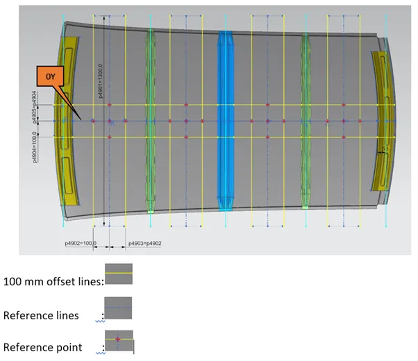
a. On plane parallel to the top plane draw sketch in which 0Y is projected alog the direction perpendicular to top plane
b. Draw lines perpendicular to 0Y line passing through point exact midpoint of the two adjacent parts (e.g., midpoint between front rail and bow roof 1)
c. Offset these reference lines on both sides by 100 mm
d. Mark intersection points (red points) of reference line (Blue lines) and 100 mm offset lines (Yellow lines)

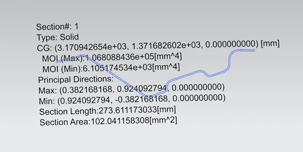
Section modulus-
- MOI for Front roof rail
MOI for Bow roof rail 1
MOI for Centre roof rail
MOI for Bow roof rail 2
MOI for Rear roof rail
Conclusion-
- Using all input data we have successfully designed Ditch area flanges, Front roof rail, Bow roof rail 1&2, Rear roof rail as per the requirement
- As per heat distortion criteria we come to know all bow roof positions are OK
- As per Snow load criteria we come to know there is improvement required
- All roof rails draft analysis are found OK