Roof challenge
ROOF
Introduction
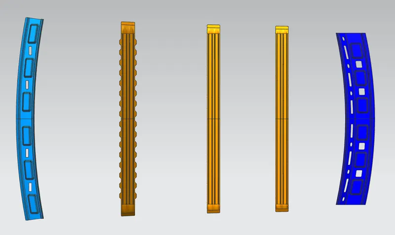
An automobile roof is the portion of an automobile that sits above the passenger compartment, protecting the vehicle occupants from sun, wind, rain, and other external elements. The roof has under lying reinforcements that are primarily installed below the roof to enhance strength. These are the Front Roof Rail, Rear Roof Rail, Centre Roof Rail, and Bow Roofs.
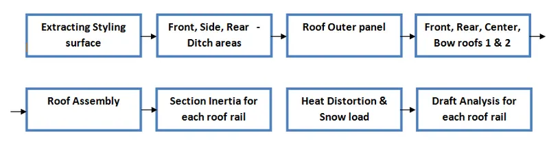
Design Methodology:
Roof Outer panel
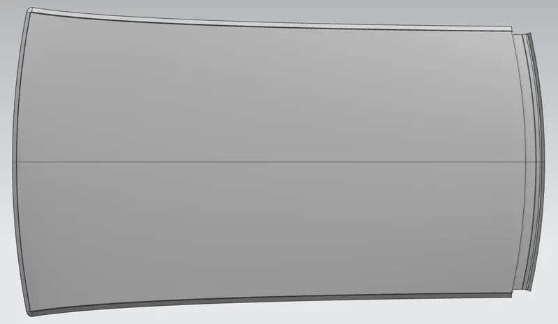
This is the outer & styling surface of the roof assembly, based on which the roof strength calculations design of roof rails and their master section development are made.

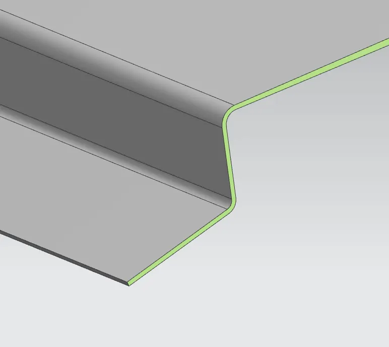
Ditch area
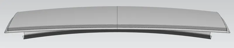
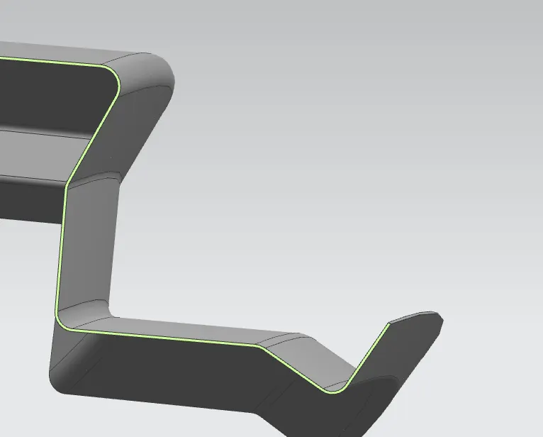
The Ditch Area is the extended portion of the main Roof concealed by other BIW panels. The rail supports of the roof are attached to the Ditch Area using Spot welds.
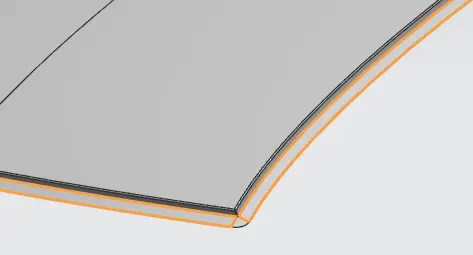
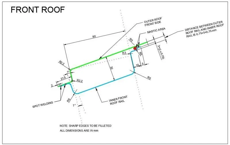
Front Rail
It is the support that is joined with the windshield glass. The front headroom clearance and the visibility criteria need to be considered while designing the roof rail
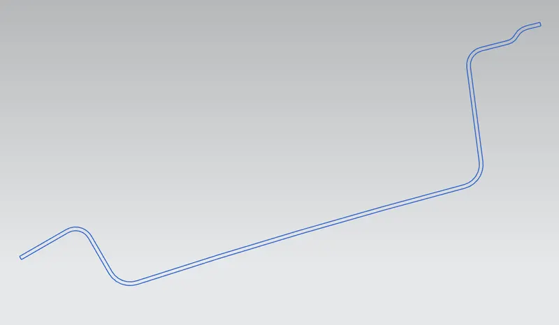
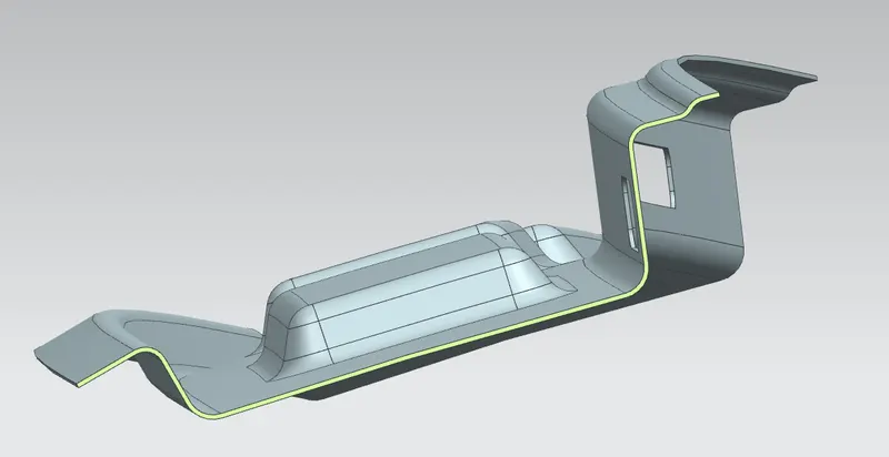
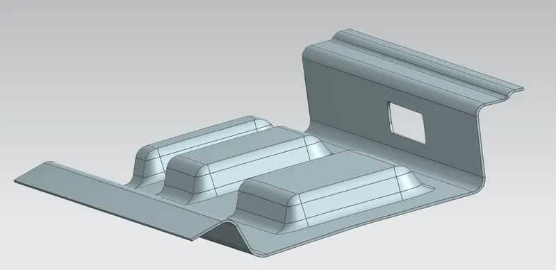


Rear Rail
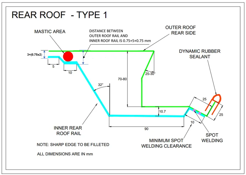
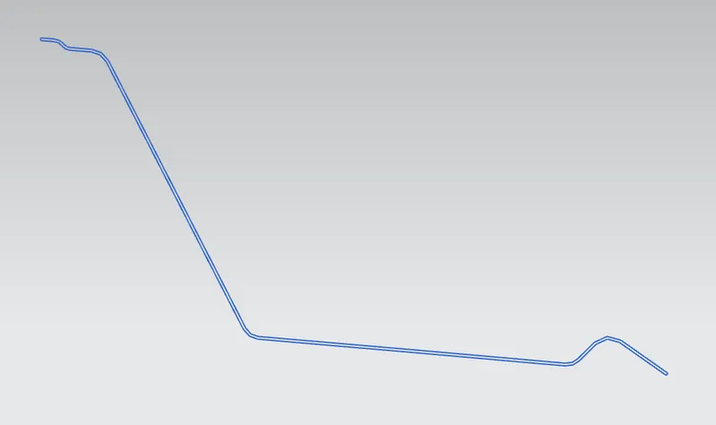
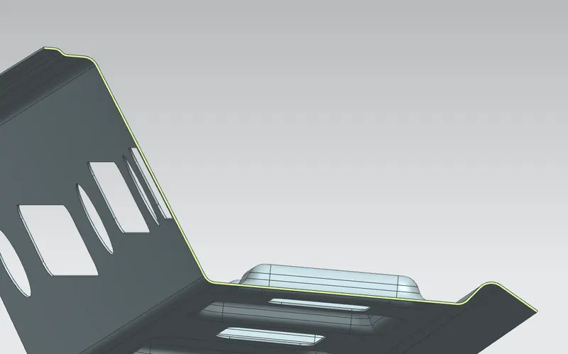
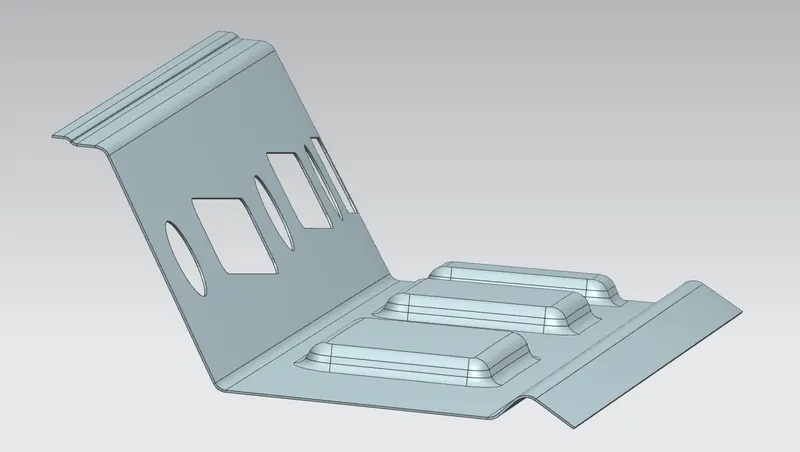
It is the support that is joined to the back door and the Body side outer and the inner panels. We have to take into consideration the rear headroom clearance and the rear visibility criteria while designing the rear roof rail from the backdoor design. Spot welds are applied at the back door end of the rail and the other end is joined with the roof using Mastic sealants.

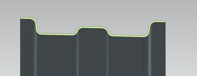
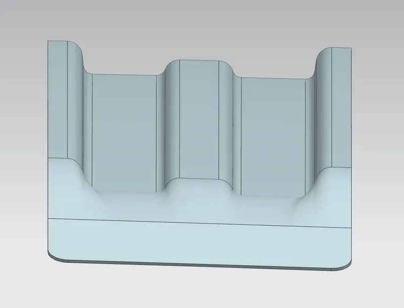
Center rail & Bow Roofs
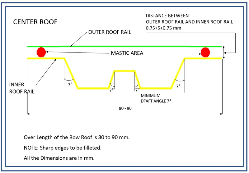
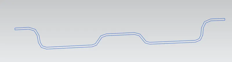
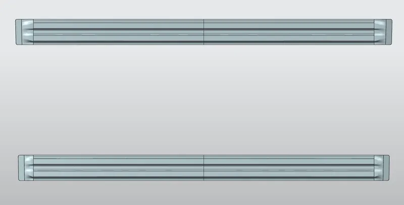
The Centre roof rail and Bow roof rails -1 & 2 are placed between the Front and Rear roof rails. Considering the aesthetics, spot weld is not applied for joining these rails to the roof panel. Instead mastic sealants are used at both ends.
Center rail
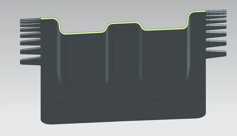
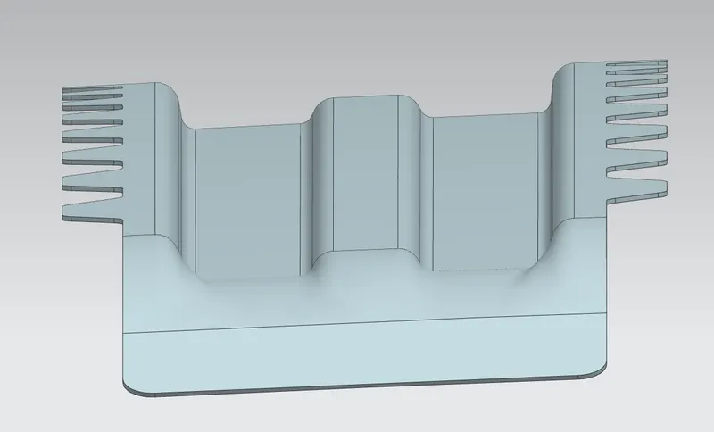


Bow roof 1 & 2
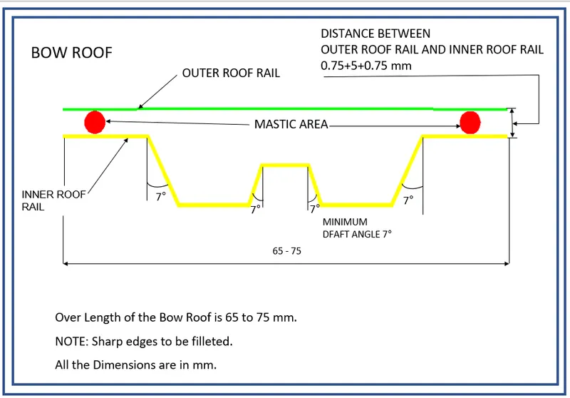
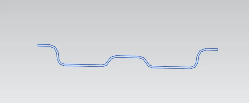


Mastic Sealants:
Bow Roof Rails and Centre Roof Rail are joined with the help of Mastic Sealant. Here we cannot use the Spot welding because it damages the aesthetic surface area of the Roof. So, the mastic sealant is used in this area.
Roof Assembly
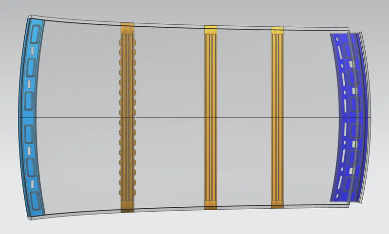
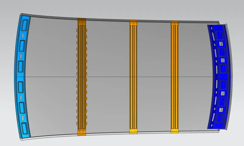
The Roof rails are assembled with the roof outer panel in the below order from the front end of the outer panel to its rear end;
- Front rail
- Center rail
- Bow roof 1
- Bow roof 2
- Rear rail


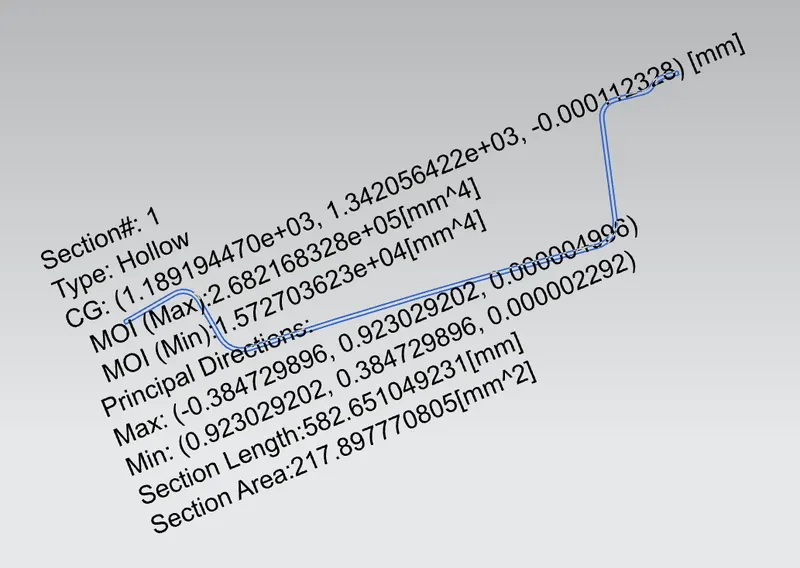
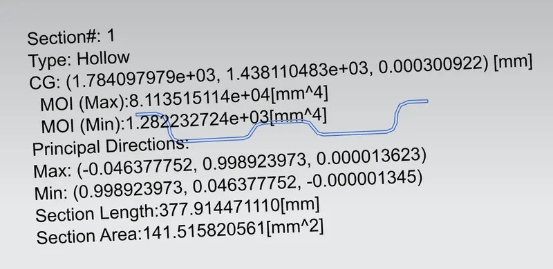
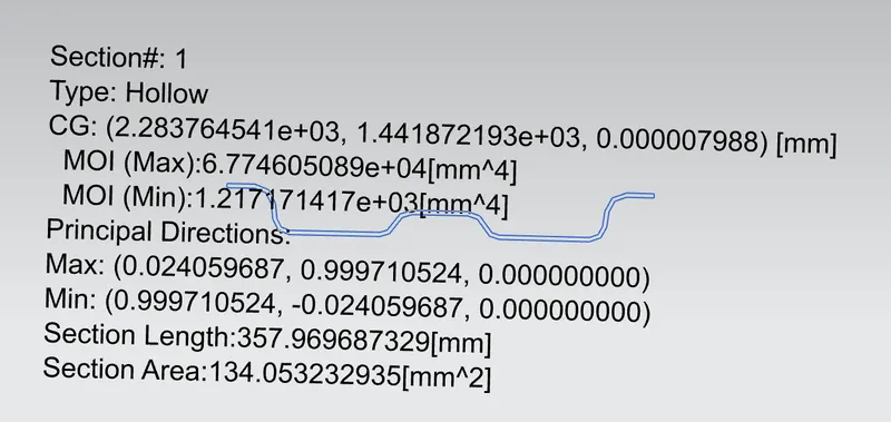
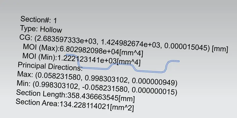
Moment of Inertia for the Roof Rails
Front rail
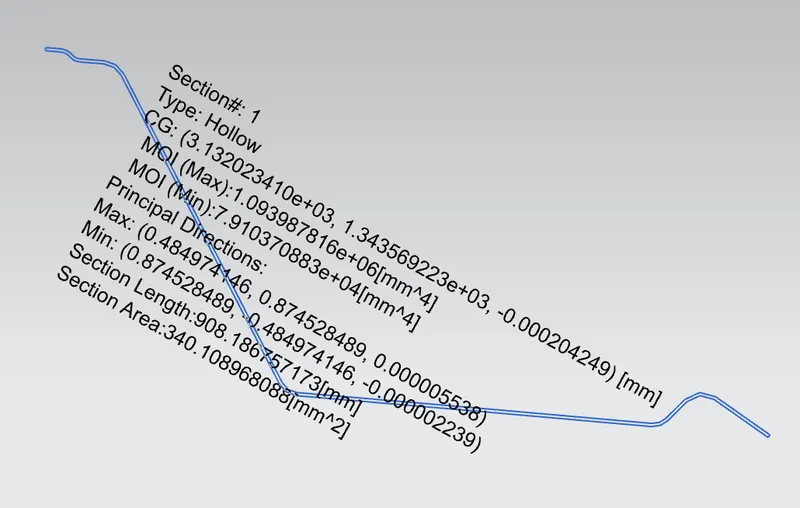
Rear rail
Center rail
Bow roof 1
Bow roof 2
Curvature study
Heat Distortion Criteria
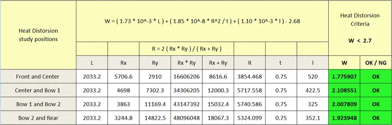
W = ( 1.73 x 10⁻³ x L ) + ( 1.85 x 10⁻⁸ x R2 / t ) + ( 1.10 x 10⁻³ x l ) - 2.68
Where,
L = Roof Length in X-Direction, mm (Roof dimension in 0-Y)
R = Roof curvature
R = 2 ( Rx * Ry ) / ( Rx + Ry )
Rx = X curvature
Ry = Y curvature
t = Roof plate thickness, mm
l = Bow Roof Span, mm
Judgment Condition
W < 2.7
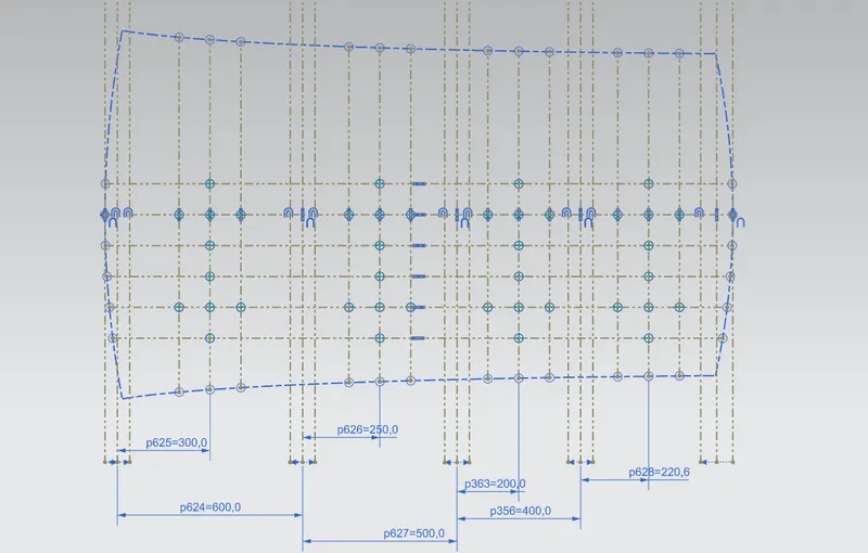
Rx & Ry (X & Y Curvature):
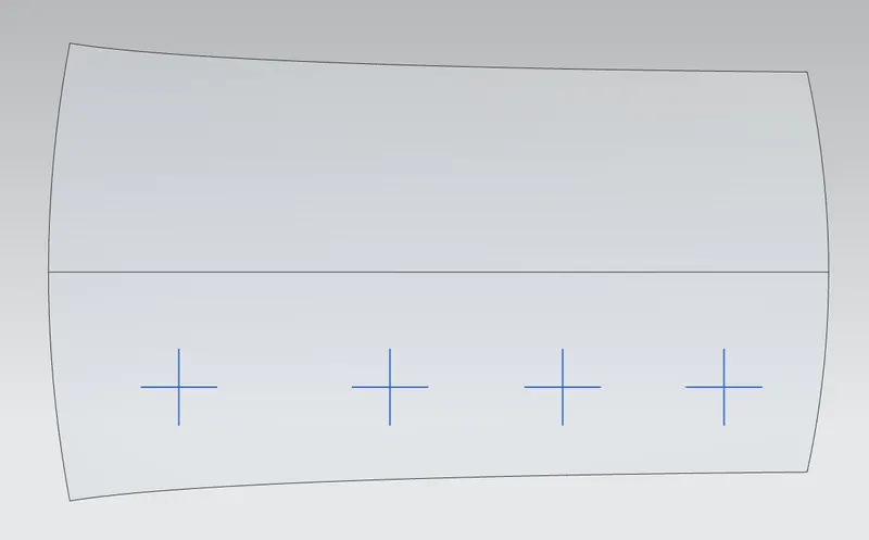
- From 0-Y axis, at -3Y about distance 300mm is drawn parallel, then 100 mm lines are offset to either side of -3Y line.
- Now centre lines are drawn between each adjacent roof rail edges respectively. Intersection points are marked.
- Project the intersection points to roof surface
- Join the projected points using curve and measure the minimum radius and linear dimensions.
Snow Load criteria
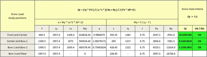
Qr = ( Iy x t2 ) / ( α x s x (( Rx + Ry ) / 2 )2 x 10⁻⁸ )
Where,
α = My x Lx2 x 10-12, My = Y ( Ly – Y )
t = Roof plate thickness, mm
Ly = Distance between the front and rear roof Rails on the Vehicle along with 0Y, mm
Lx = Distance between the Left and Right end of the roof on the Roof BOW, mm
Y = Distance Front Rail to Roof BOW, mm
s = Distance for which Roof Bow bears divided load, mm
s = L1 / 2 + L2 / 2
Iy = Geometrical moment of inertia of Roof BOW, mm4
Rx = Lateral direction curvature radius of roof panel Y cross-section on Roof BOW, mm
Roof panel curvature Radius of the Length Lx in Front view
Ry = Longitudinal Direction curvature radius of the Roof panel X cross-section on Roof BOW, mm
Roof panel X curvature radius of length s in Side view
Judgment condition
Qr ≥ 3.1
Rx & Ry
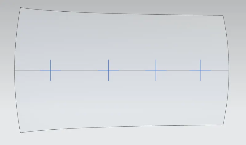
- At 0-Y axis draw lines 100 mm offset to either side of 0Y axis line.
- Now centre lines are drawn between each adjacent roof rail edges respectively.
- Intersection points are marked.
- Project the intersection points to roof surface.
- Join the projected curves using arc curve and measure the minimum radius and linear dimensions.
Draft Analysis:
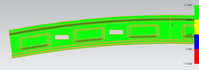
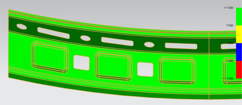
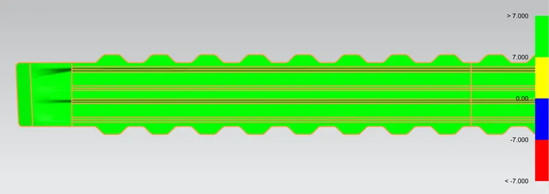
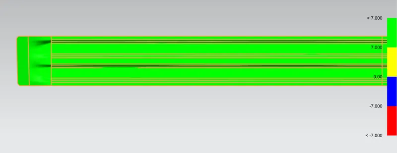
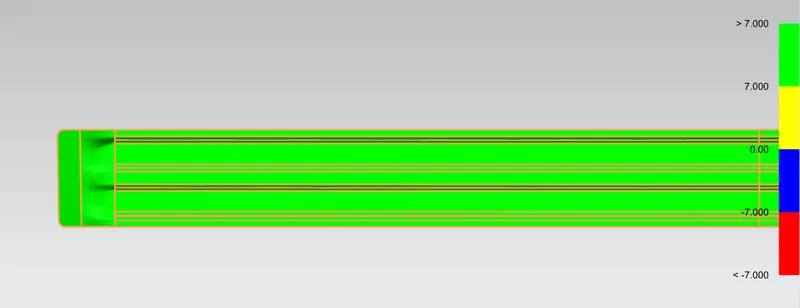
Draft analysis is a method of checking the draft angle on various faces of a part in a particular direction. It should be more than 7 degrees. The Draft analysis results of each roof rail is positive in this case.
Front rail
Rear rail
Center rail
Bow roof 1
Bow roof 2
Conclusion
Thus the designed roof assembly satisfies both the Heat distortion & Snow load criteria, The Roof assembly design is done good.