Roof challenge
AIM : we are desiging the roof and its componentss, by taking care of its design consideration , how do we fix them and where do we positioning them.
while designing the roof , following points to be note down.
1. Design requirements for the Roof and its components
2. Functional requirements
3. Types of Roofs and their functionality
4. ROLL over test Regulation and requirements
5. Identification Methods to increase the strength of the roof
6. material identofication techniques
7. Joining techniques like Mastic, welding.
8. Accessory part purpose and reuirements.
9. gap and flushness requrements.
INTRODUCTION
ROOF is the top portion of an automobile that sits above the passenger compartment, protecting the vehicle occupants from sun, wind, rain, and other external elements.
The Car Roof Consists of the following parts:
- The outer panel
- Front roof Rail
- Bow Roof
- Centre Roof Rail
- Rear Roof Rail
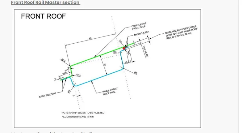
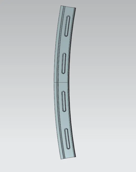
FRONT ROOF RAIL :
It is the one which joins with the wind shield glass and the front roof rail and the body side outer. It is an additional commodity which is being given as a reinforcements and also has certain features in it, which will be supporting the bracket map lamp and the room lamp, which is being mounted on this front roof rail.
Design criteria for designing front roof rail
1. Minimum head room clearance
REAR ROOF RAIL :
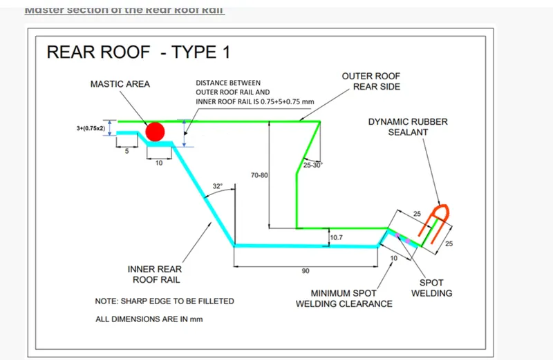
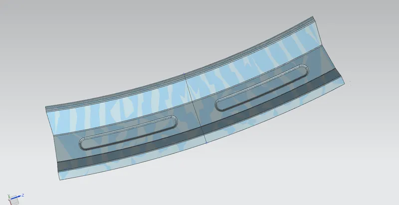
Rear roof rail is the one which joins with the back door and body side outer.
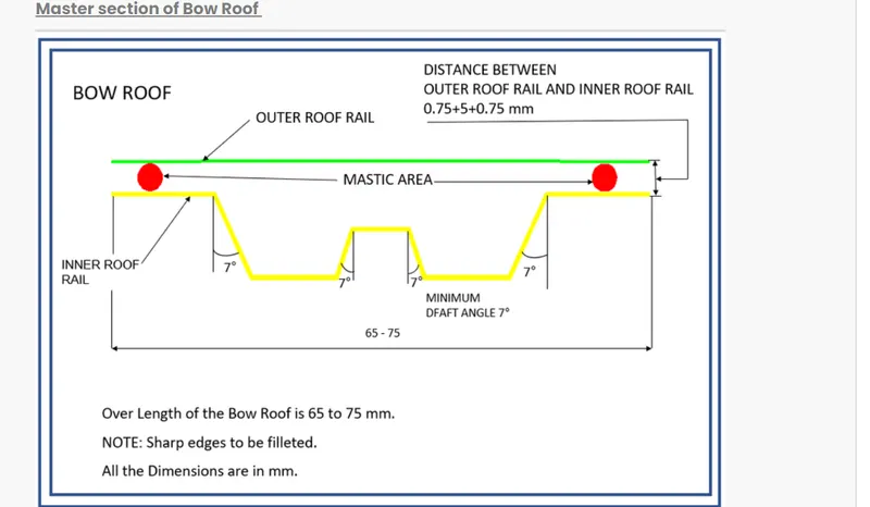
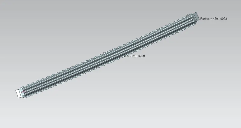
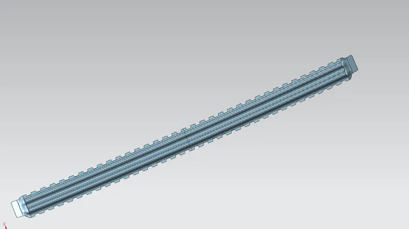
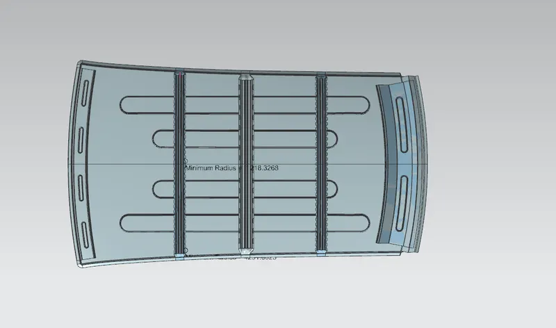
BOW ROOF : It is used to give strength to the roof . It is is placed between the front roof and centre roof . Another bow roof 2 is also placed between the centre roof and rear roof. we should placed these bow roof in such a way that it justify the curvature part.
BOW ROOF 1 :
BOW ROOF 2:
Centre sun roof : In this , centre bow roof is provided in order to increse the strngth. here i have given reinforcements in the centre sun roof , so that if we cut the part for the sun roof, its strength will be decrese, in order to maintain that strength, we need to provide more strength.
- Sunroofs - A sunroof is a movable panel that opens to uncover a window in an automobile roof, allowing light and/or fresh air to enter the passenger compartment. Sunroofs can be manually operated or motor driven, and are available in many shapes, sizes and style.
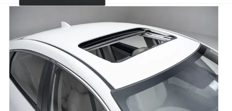
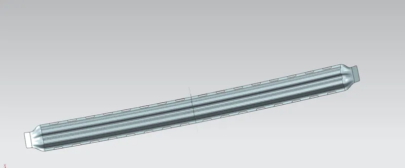
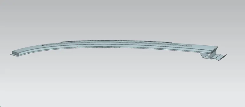
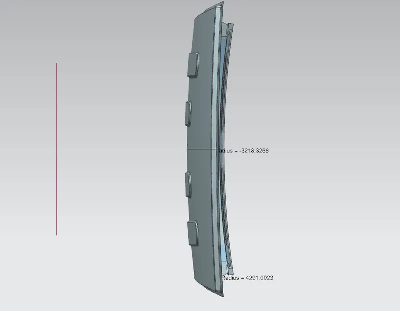
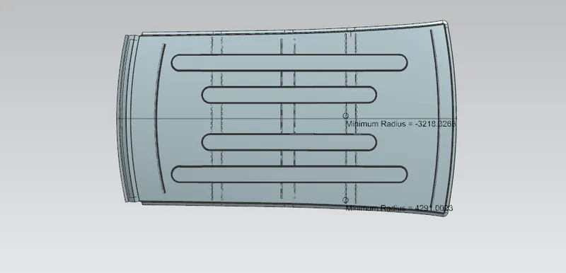
ROOF IMAGES :
MANUFACTURING PROCESS OF SHEET METAL DESIGN :
- Shearing Operations :a sheet metal workpiece is placed or kept between two dies from one end. And, the punch is hit at the other end of the sheet, producing a shearing effect.
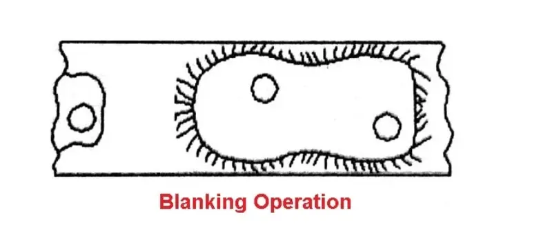
2. Blanking Operations : It is an operation of cutting a whole piece from sheet metal. In which enough scrap is left all around. A punch and die is applied for this type of sheet metal operation.
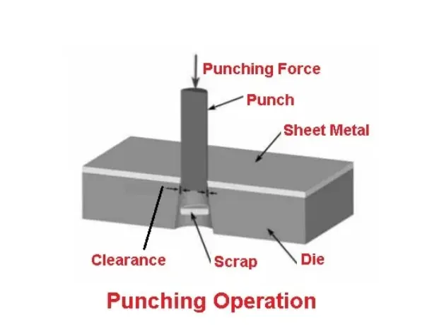
3. Punching Operations :It is an operation of producing circular holes on a sheet of metal by a punch and die. This is the exact opposite of blanking but the operation is nearly the same. A Punch and die are further used here such as blanking operations.
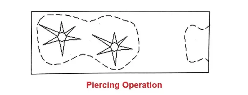
4. Piercing Operations :It is the process in which desired shape holes are produced in a piece of sheet metal without eliminating any material from the sheet or removing a very small amount of material . Both punch and die are also applied in this operation. The punch used in the piercing operation is usually bullet-shaped.
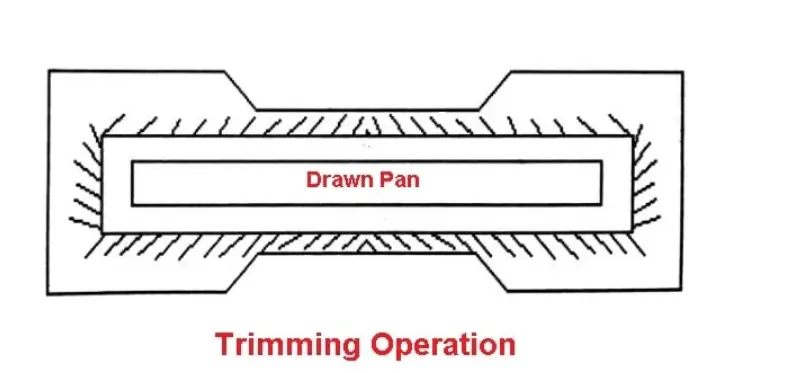
5. Trimming Operations : The trimming operation is also known as shaving operation. It is a finishing operation by removing the burrs from the cut edges is taken out in order to make edges smooth and also provide dimensional accuracy.
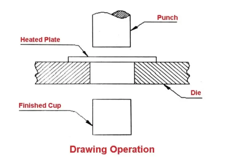
6. Drawing Operations :
It is an operation of producing thin-walled hallows or vessel shaped parts from sheet metal. It can be divided into two categories:
- Deep drawing :The length of depth of the object to be drawn is deeper than its width.
- Shallow drawing : The length of the object to be drawn is less than its width. The examples of drawing are pans, tubes and cams.
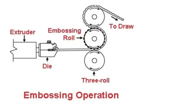
7. Embossing Operations :It is the metalworking operation which is used to create raised surfaces or lettering in sheet metal. There is no change in metal thickness during this operation.
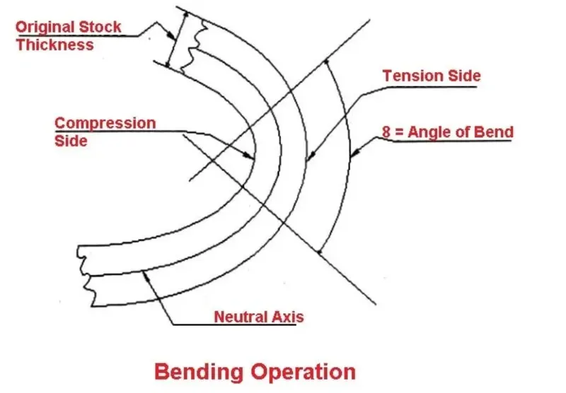
8. Bending Operations :It occurs when forces are applied to localized areas. Here the metal flow is uniform along the bend axis with the inner surface in compression and outer surface in tension.
Types of bending:
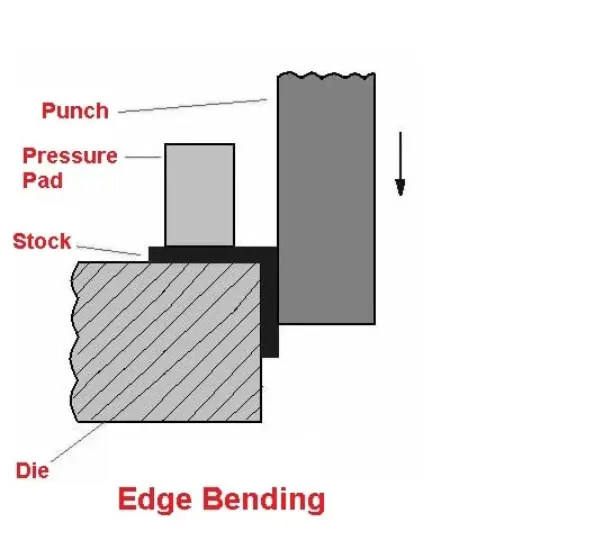
- Edge bending: It is a type of bending operation, In which a piece of sheet metal is fixed or held between two dies from one end. Then the other end is forced to strike upon the punch which is free or unfixed. Thus, the free or unfixed edge of the sheet metal piece is bent to make the forming process.
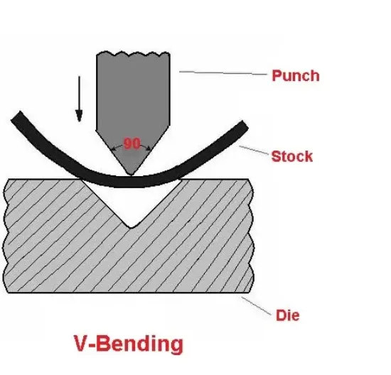
2. V-bending : n these type of bending operation, when a piece of sheet metal is pressed between the die and the punch; It is formed into a V-shape in the die.
3. U-bending : In this type of a bending operation, in which when the punch is pressed by a force to move into the die, the sheet metal piece gets formed into a U-shape.

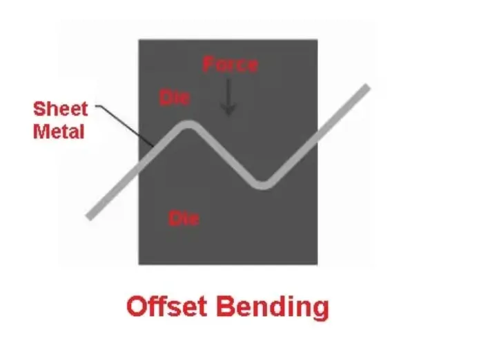
4. Offset bending : It is a type of bending operation, in which a piece of sheet metal is formed into an offset shape with the help of a punch and die.
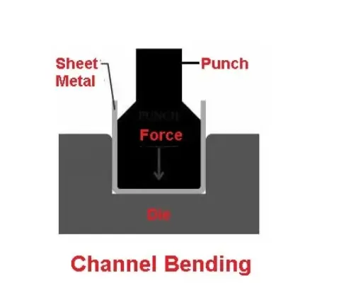
5. Channel bending : In this type of a bending operation, in which when a force is used to the punch to move into the die, the sheet metal piece, in between the punch and die, gets the shape according to the shape of the die and punch i.e. a channel shape.
- Squeezing Operations : It is a quick and widely used way of forming ductile metals. It has different operations such as sizing, coining, riveting etc.
1. Sizing : This operation is a squeezing operation that reduces the thickness of the metal. The sizing is done in an open die and only the surface where the die and workpiece touch will be sized.
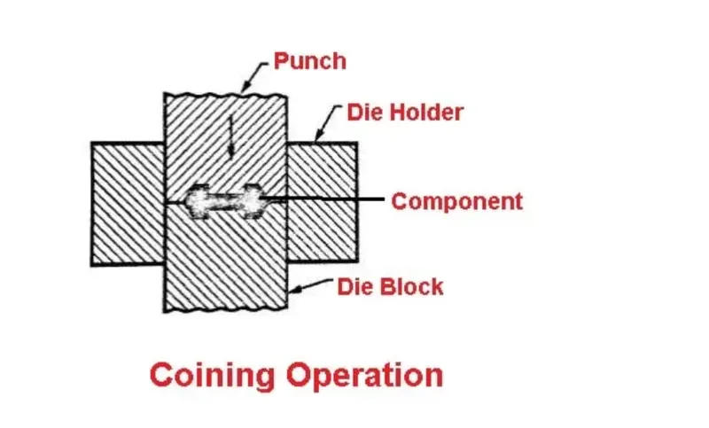
2. Coining : It is a process of pressing metal in a die so that it flows into the die space. For example Medals, Coins, and Jewellery.
HEAT DISTORTION CRITERIA :
we are doing the heat distortiion test , for temperature variation. Due to rapid cooling and heating of the material , it will result in bending , so for that we need to test these heat distortion.
In this we are testing the -300 offset from the centre 0-y line, because the SUN has 23.5 degree tilt from its axis, so temperature from the sun dont hit dirctly to the centre, it deviates . Therefore we have offset from the centre.
Bow–Roof Prediction Formula
W = [1.73 x 10^(-3) x L] + [1.85 x 10^(-8) x (R^2)/t] + [ 1.10x10^(-3) x l] - 2.68
Where,
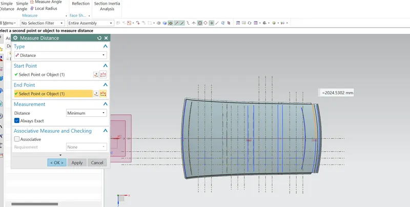
L = Roof Length in X-Direction[mm](Roof dimension in 0-Y)
R = Roof curvature
R = 2(Rx*Ry)/(Rx+Ry)
Rx = X curvature
Ry = Y curvature
t = Roof plate thickness [mm]
l = Bow Roof Span [mm]
Judgment Condition
OK< 2.7
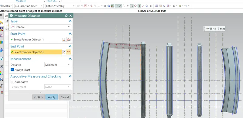
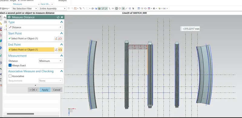
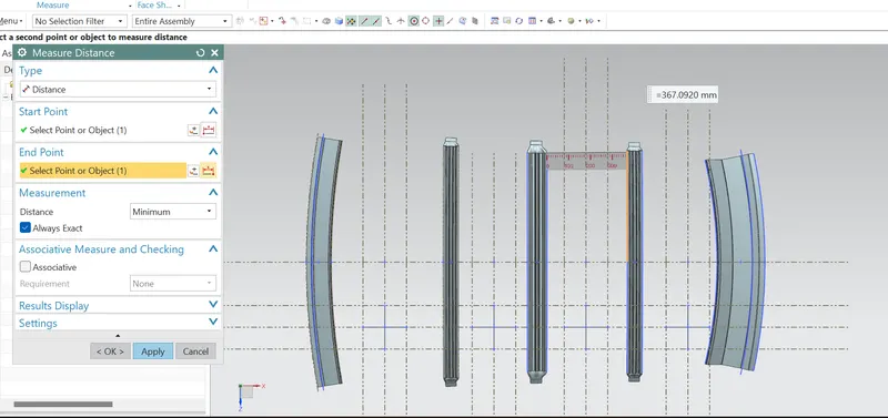
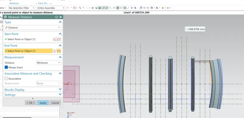
TO MEASURE DISTANCE OF L :
Ry 1 :
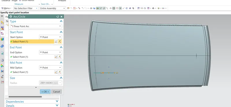
RY2 :
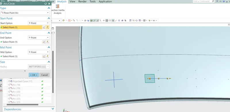
RY3 :
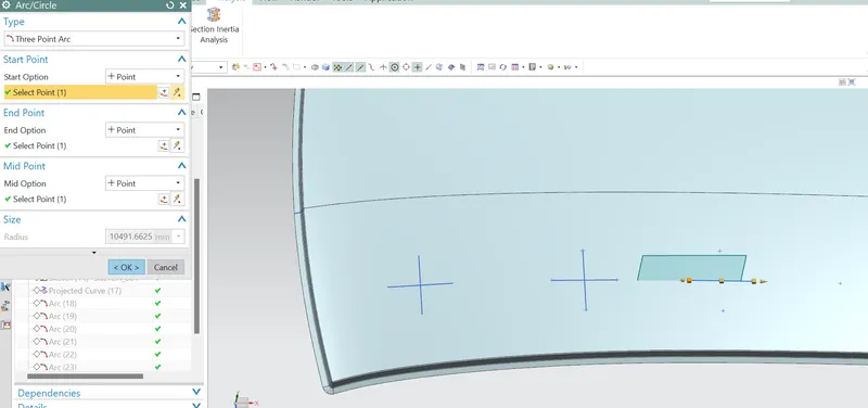
RY4 :
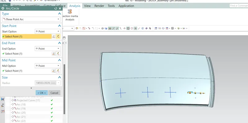
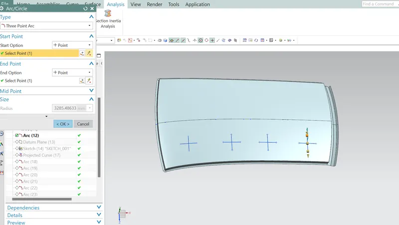
RX1
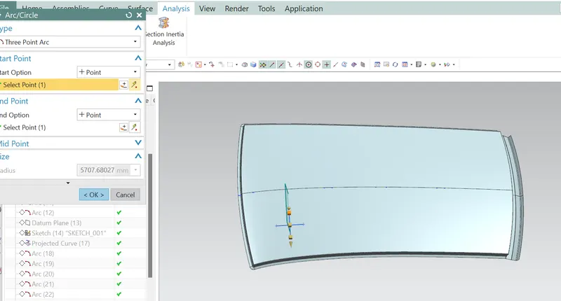
RX2
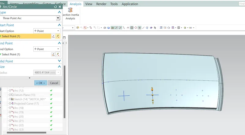
RX3
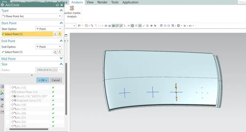
RX4
i1
for i2
i3
i4
| heat distortion | HEAT DISTORTION CALCULATION | |||||||||
| s.no | bow roof | Rx | Ry | R | t | I | L | (R^2/t) | W | RESULT |
| 1 | FRONT ROOF to BOW ROOF 1 | 5707.68 | 2891.66 | 3838.591 | 0.75 | 465 | 2024.53 | 1.74E+07 | 1.65 | pass |
| 2 | BOW ROOF 1 to Centre SUN ROOF | 4803.41 | 6877.013 | 5656.14 | 0.75 | 315.2217 | 2024.53 | 4.26E+07 | 1.95 | pass |
| 3 | CENTRE SUN ROOF to BOW ROOF 2 | 3996.85416 | 10491.66 | 5788.529 | 0.75 | 367.092 | 2024.53 | 4.46E+07 | 1.96 | pass |
| 4 | BOW ROOF 2 to REAR ROOF RAIL | 32854.4863 | 14553.35 | 5360.755 | 0.75 | 288.4706 | 2024.53 | 3.83E+07 | 1.84 | pass |
SNOW LOAD :
we have been testing the snow load condition for the snow accumulating over the car , as countries which faces very less temperature , for that we need to test the snow load criterion.
For test to be done on the outer roof , it lies at the centre of 0-y line , because there is chances of accumulating the snow at centre part of the roof.
Snow Load Prediction Formula
Qr = [Iy x t2] / [α x s x [(Rx + Ry)/2]2 x 10-8]
Note: The Qr value given over here is correct. There was a typo error in the formula given in the video.
Where,
α = My x Lx2 x 10-12 , My = Y(Ly-Y)
t = Roof plate thickness [mm]
Ly = Distance between the front and rear roof Rails on the Vehicle along with 0Y[mm]
Length of Roof panel with the center point between Roof rail Front /Rear as the front and rear reference point.
Lx = Distance between the Left and Right end of the roof on the Roof BOW [mm]
The width of the roof panel is exposed on the surface.
Y = Distance front Front Roof Rail to Roof BOW[mm]
s = Distance for which Roof BOW bears divided load [mm]
s = L1/2 + L2/2
Iy = Geometrical moment of inertia of Roof BOW (Y cross-section )[mm4]
Rx = Lateral direction curvature radius of roof panel Y cross-section on Roof BOW [mm]
Roof panel curvature Radius of the Length Lx in Front view
Ry = Longitudinal Direction curvature radius of the Roof panel X cross-section on Roof BOW [mm]
Roof panel X curvature radius of length s in Side view
Judgment condition
Qr ≥ 3.1
250 ≤ s ≤ 380
Snow Load Prediction Formula
Qr = [Iy x t2] / [α x s x [(Rx + Ry)/2]2 x 10-8]
Note: The Qr value given over here is correct. There was a typo error in the formula given in the video.
Where,
α = My x Lx2 x 10-12 , My = Y(Ly-Y)
t = Roof plate thickness [mm]
Ly = Distance between the front and rear roof Rails on the Vehicle along with 0Y[mm]
Length of Roof panel with the center point between Roof rail Front /Rear as the front and rear reference point.
Lx = Distance between the Left and Right end of the roof on the Roof BOW [mm]
The width of the roof panel is exposed on the surface.
Y = Distance front Front Roof Rail to Roof BOW[mm]
s = Distance for which Roof BOW bears divided load [mm]
s = L1/2 + L2/2
Iy = Geometrical moment of inertia of Roof BOW (Y cross-section )[mm4]
Rx = Lateral direction curvature radius of roof panel Y cross-section on Roof BOW [mm]
Roof panel curvature Radius of the Length Lx in Front view
Ry = Longitudinal Direction curvature radius of the Roof panel X cross-section on Roof BOW [mm]
Roof panel X curvature radius of length s in Side view
Judgment condition
Qr ≥ 3.1
250 ≤ s ≤ 380
RY1
RY2
RY3
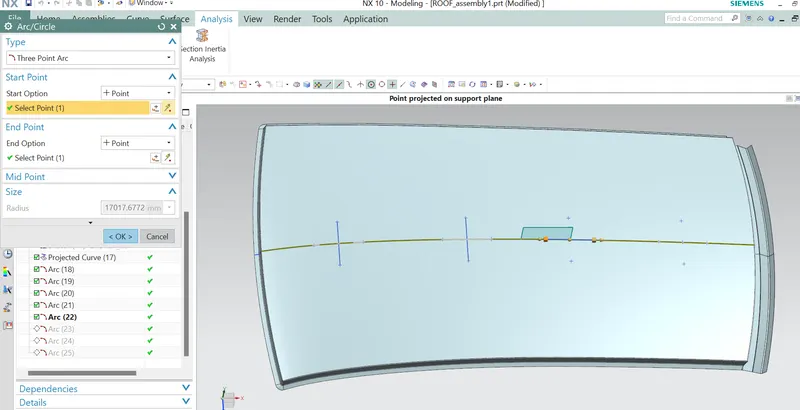
RY4
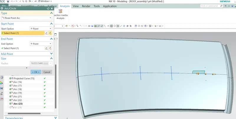
RX1
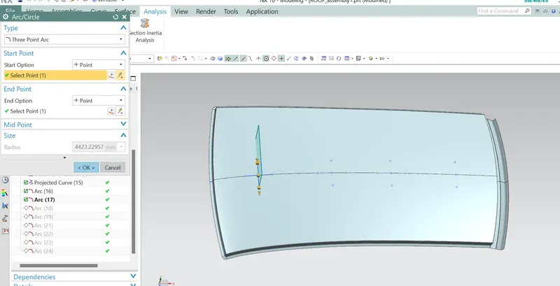
RX2
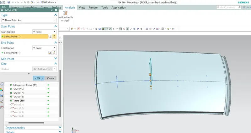
RX3
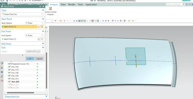
RX4
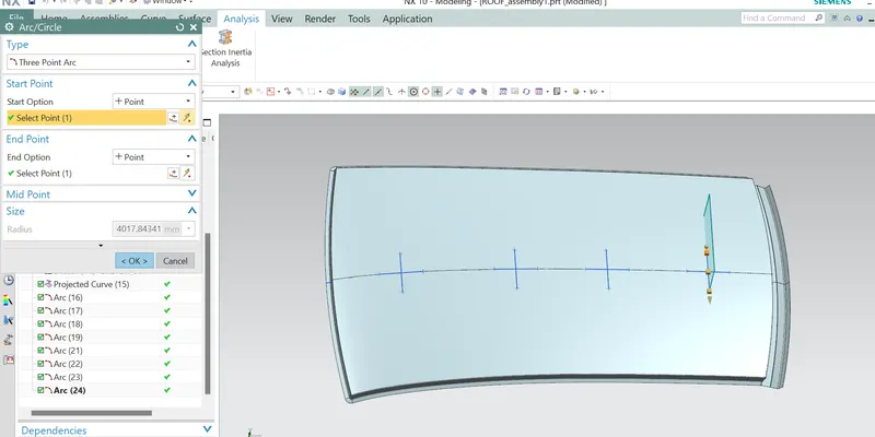
LY
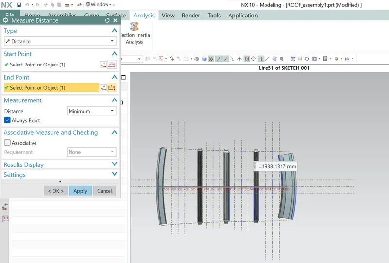
LX1
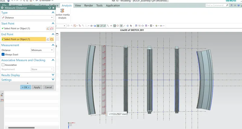
LX2
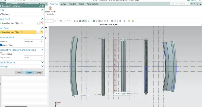
LX3
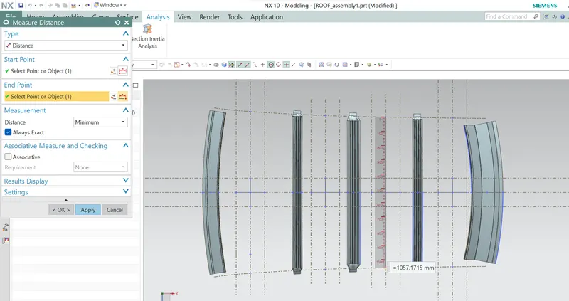
LX4
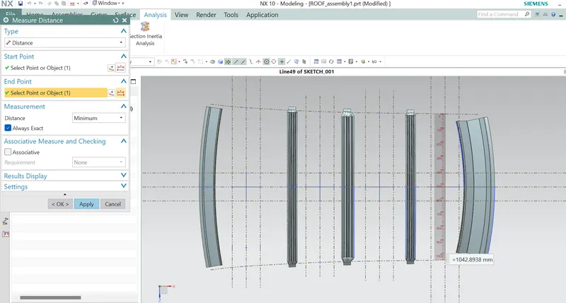
Y1
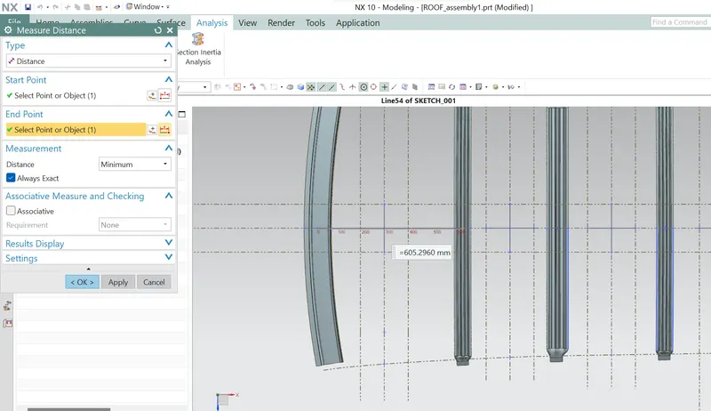
Y2
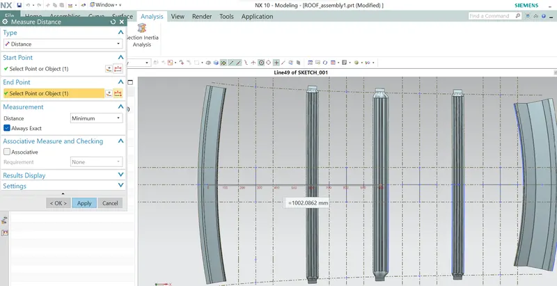
Y3
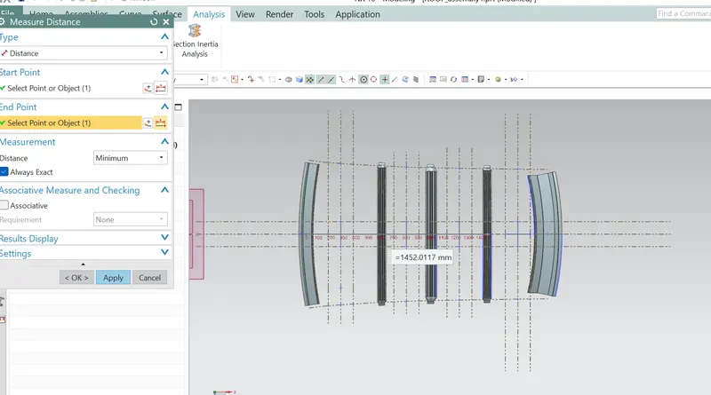
Y4
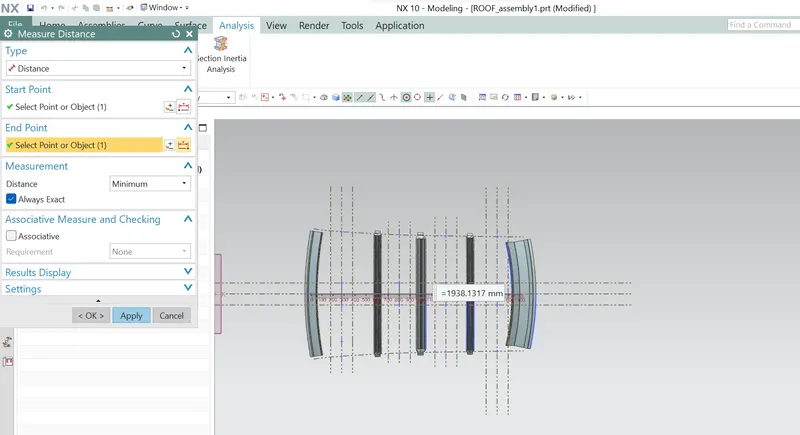
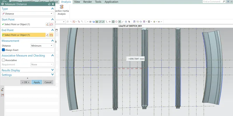
FIRST SECTION :
L1
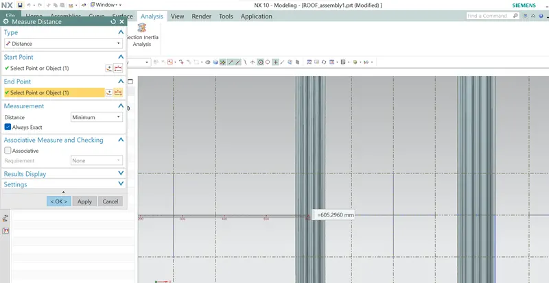
L2
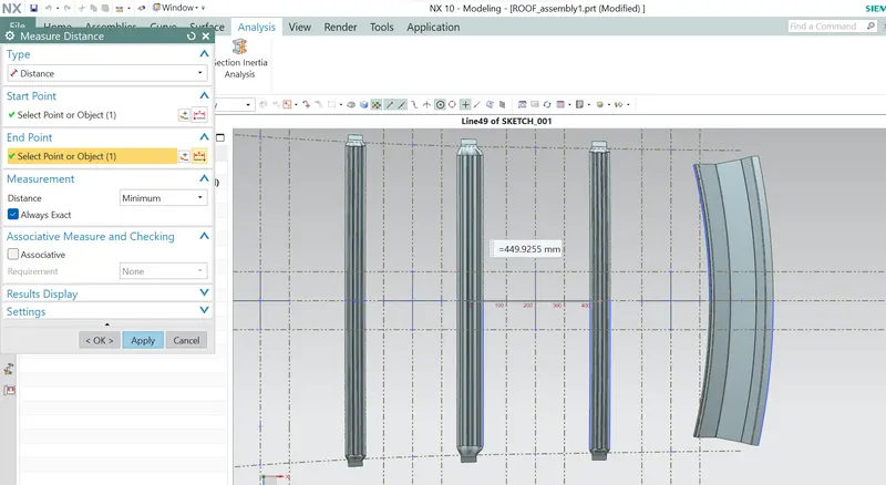
FOR SECOND SECTION
L1
L2
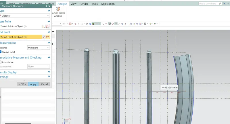
FOR 3RD SECTION
L1
L2
FOR FOURTH SECTION
L1
L2 = 0
MOMENT OF INERIA : It is used to calculate how much the strength has in its components, greater the area , greater will be strength.
FRONT ROOF :
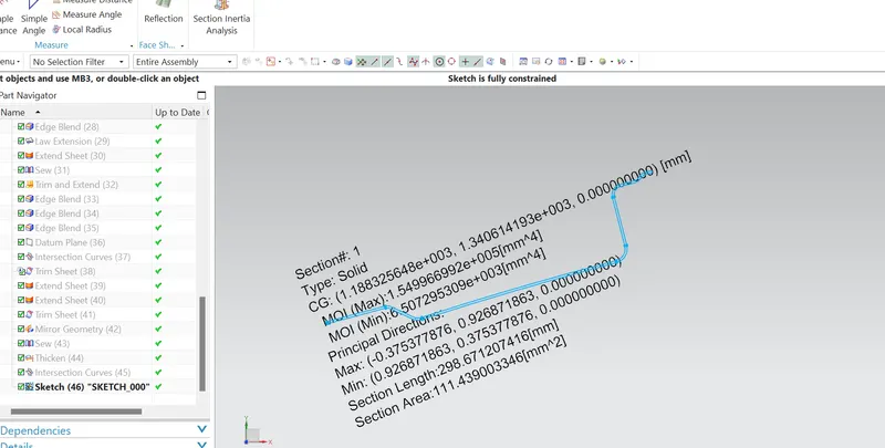
REAR ROOF :
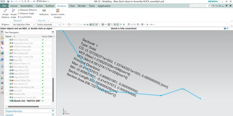
BOW ROOF 1
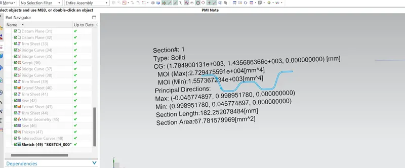
CENTRE SUN ROOF :
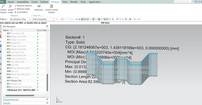
BOW ROOF 2
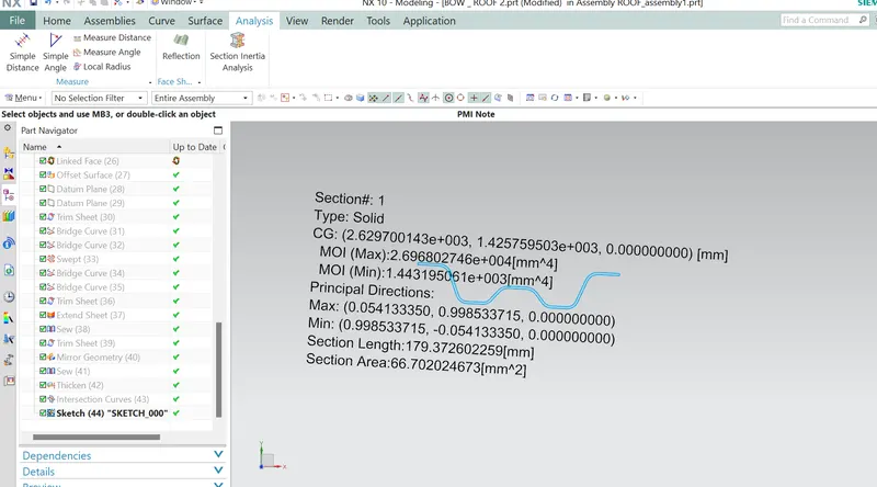
calculations of the snow load condition from the above values which we have get .
| s.no | bow roof | RX | RY | LX | LY | L1 | L2 | t | Y | S | My | Iy | alpha | Qr | result |
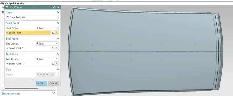
| 1 | FRONT ROOF to BOW ROOF 1 | 4423.23 | 2761.87 | 1133.29 | 1938.31 | 605.29 | 690.78 | 0.75 | 605.29 | 648.02 | 806754.72 | 6500 | 1.03 | 42.44 | pass |
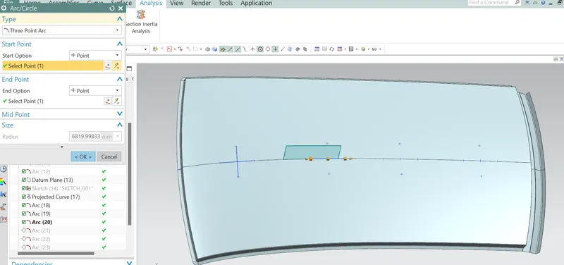
| 2 | BOW ROOF 1 to Centre SUN ROOF | 3811.86 | 6819.99 | 1077.08 | 1938.31 | 690.7841 | 449.925 | 0.75 | 1002.08 | 570 | 938597.82 | 1550 | 1.08 | 5 | pass |
| 3 | CENTRE SUN ROOF to BOW ROOF 2 | 11859.57 | 17017.67 | 1057.17 | 1938.31 | 449.9 | 486.12 | 0.75 | 1459.011 | 468 | 699038 | 2420 | 0.78 | 1.7 | fail |
| 4 | BOW ROOF 2 to REAR ROOF RAIL | 4017.843 | 16353.54 | 1042.89 | 1938.31 | 486.1 | _ | 0.75 | 1938.13 | 243 | 0 | 1440 | 0 |
FOR THE FAIL RESULTS , WE NEED TO DO SOME CHANGES FOR GETTING BETTER RESULTS, FOLLOWING POINTS NEED TO DO .
1. modified the radius of curvature gradually of the roofs.
2. position of the bow roof, for this we look at the cenre region weather it is flat or not. Generally we go with the flat surface
3. Reduce Non -Mastic influence area,so that we have a better strength to the roof.
4. Local embosses over the car, this will give a drastic improvement in the strength.
DRAFT ANALYSIS:
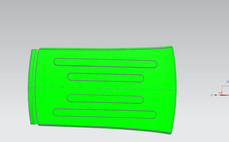
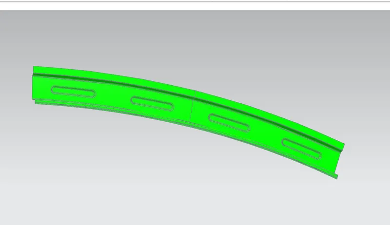
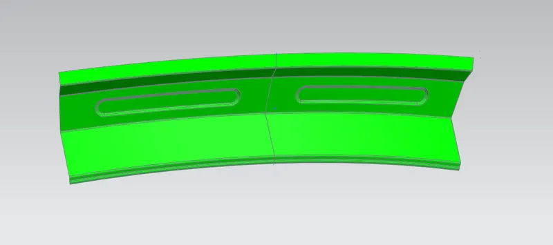
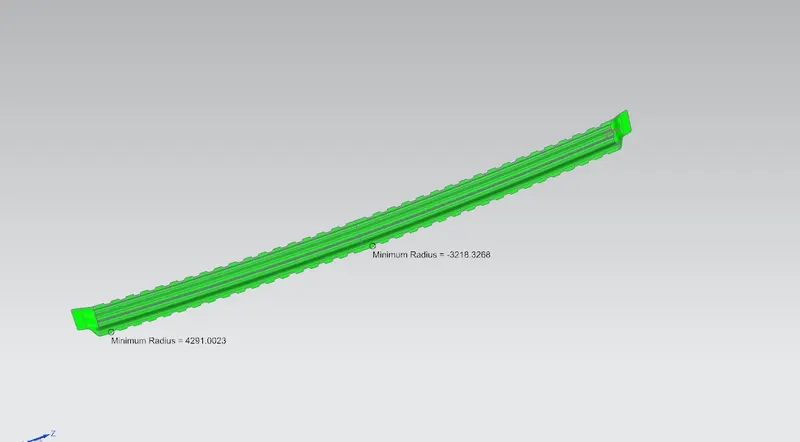
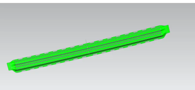
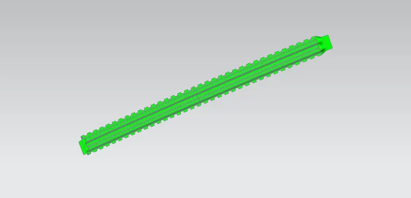
The part has to be fully constrained , as it doesn't have any negative draft or how does the part behave .
Before sending to the simulation department , we need to check that we should not have any underuts in our part and have maintained n (3 + thickness ) radius. In addition to this, we need to maintain minimum hole requirements gap.
After all the things is done in desiginig , there are various test needs to be done in order to check the strength , before it came on road.
- Car Roll-over Test - The rollover test conducted by NHTSA subjects vehicles to a handling maneuver called a fishhook which is a term used for quick left-right turn at speeds ranging from 35 to 50 miles per hour. The operation is a simulation of the driver overdoing the vehicle steering usually happens during emergency situations.
. Roof Crush Test - In this test the load is applied on the roof to test the strength in static car postion
. FMVSS 216 Roof Crush : The purpose of the FMVSS 216(Federal motor vehicle safety standard) is to reduce the head injuries, neck injuries and deaths by the roof crush of the car in to the passenger compartment in rollover crashes.
CONCLUSION :
THUS, we have design the roof with all the strength while considering all the design consideration using nx cad software.