Roof challenge
Roof challenge
…
Aim- To design and implement reinforcements and flanges with appropriate dimensions and verify the design by performing Heat Distortion, Snow Load and Draft analysis.
Software: Siemens NX-CAD, student version.
Roof- According to Wikipedia (https:// en.wikipedia.org/wiki/Automobile_roof), an automobile roof is the portion of an automobile that “sits above the passenger compartment, protecting the vehicle occupants from sun, wind, rain, and other external elements,” and helping ensure their safety in the event of vehicle rollover.
Types of roof can include (with variations):
- Convertible roofs
- Hardtops
- Sunroofs
- T-tops
- Targa tops
- Vinyl roofs
Convertible roofs – According to Wikipedia, “A convertible or cabriolet is a passenger car that can be driven with or without a roof in place. The methods of retracting and storing the roof vary among eras and manufacturers. A convertible car's design allows an open-air driving experience, with the ability to provide a roof when required. A potential drawback of convertibles is their reduced structural rigidity (requiring significant engineering and modification to counteract the effects of removing a car's roof).
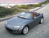
Fig 1 – 2006-07 Mazda MX-5 Miata
Hardtops – According to Wikipedia, “a hardtop is a rigid form of automobile roof, which for modern cars is typically constructed from metal. A hardtop can either be fixed,” or non-detachable, or detachable for separate storing.
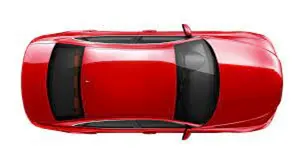
Fig 2 – Hardtop Roof
- Sunroofs – As per Wikipedia, “a sunroof is a movable panel that opens to uncover a window in an automobile roof, allowing light and/or fresh air to enter the passenger compartment. Sunroofs can be manually operated or motor driven, and are available in many shapes, sizes and styles. While the term sunroof is now used generically to describe any glass panel in the roof, the term "moonroof" was historically used to describe stationary glass panes rigidly mounted in the roof panel over the passenger compartment.” A variation on the sunroof is the moonroof, a transparent panel on the roof that is either non-moveable or only partially movable, such as tiltable. According to Wikipedia, “a moonroof has a glass panel that is transparent and usually tinted. Previous terms include Sunshine Roof, Sliding Head and Sliding Roof.”
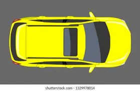
Fig 3 - Sunroof
- T-Tops – Wikipedia indicates that a “T-top is an automobile roof with a removable panel on each side of a rigid bar running from the center of one structural bar between pillars to the center of the next structural bar. The panels of a traditional T-top are usually made of auto grade safety glass.”
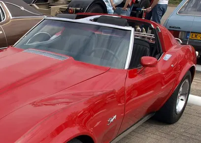
Fig 4 – T-Top (1972 Chevrolet Corvette)
- Targa Tops – According to Wikipedia, the Targa top, “or targa for short, is a semi-convertible car body style with a removable roof section and a full width roll bar behind the seats. The rear window is normally fixed, but on some targa models, it is a removable plastic foldable window, making it a convertible-type vehicle. Any piece of normally fixed metal or trim which rises up from one side, over the roof and down the other side is sometimes called a targa band, targa bar, or a wrapover band.
Targa tops are different from T-tops, which have a solid, non-removable bar running between the top of the windscreen and the rear roll-bar, and generally have two separate roof panels above the seats that fit between the window and central t-bar.”
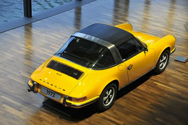
Fig 5 – Targa Top (1972 Porsche Targa)
- Vinyl Roofs - A final mainstream type of roof in production vehicles is the Vinyl roof. According to Wikipedia, “this covering was originally designed to give the appearance of a convertible to models with a fixed roof, but eventually it evolved into a styling statement in its own right. When leather, canvas and vinyl were sometimes used along with landau bars, to give a fairly accurate reproduction of a horse-drawn carriage's movable top.”
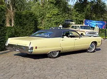
Fig 6 – Vinyl Top (1972 Chrysler Imperial Le Baron)
Solar Roof
An additional type of roof, not yet in widespread commercial use, is the Solar Roof, or a roof with a built-in solar panel. Specially-designed, lightweight solar-powered cars have traversed the entire United States and the entire continent of Australia, powered only by the Sun.
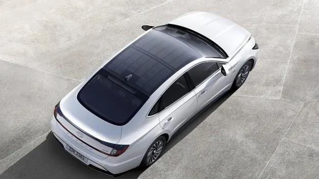
Figs 7a, b – Solar Roof and Solar Powered Car
Roof Design Criteria
Roof design follows several key criteria, as below:
- Safety
- Visibility
- Crash-worthiness
- Durability
- Heat distortion
- Snow load criteria
- Comfort
- Head clearance
- Visibility and NVH
- Manufacturability
- Draft analysis
Roof Skin
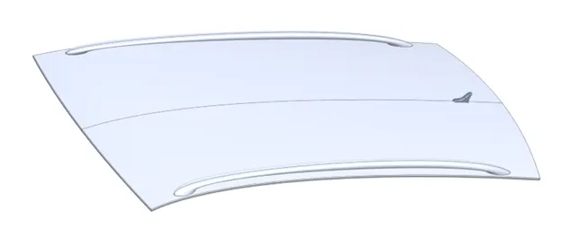
Fig 8 – Roof Provided by Design Team
We were provided a roof skin, or Roof Outer Panel, from the design team. We untrimmed it to remove the roof bar mounting surfaces, and also removed the shark fin antenna, and then used the design surface as a basis to derive the reinforcement rails.
Front Roof Rail Master Section
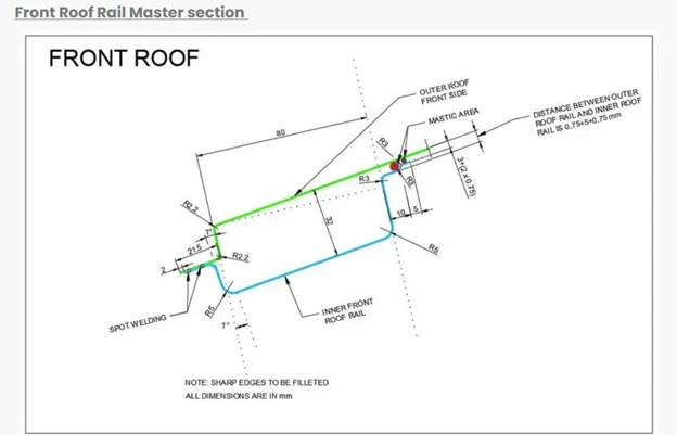
Fig 9 – Front Roof Rail
Center Reinforcement Roof Rail Master Section
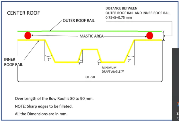
Fig 10 – Center Reinforcement Rail
Bow Roof Master Section
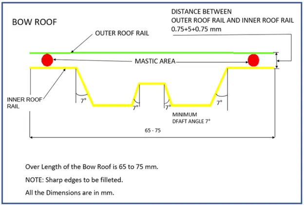
Fig 11 – Bow Roof Rail
Rear Roof Rail Master Section
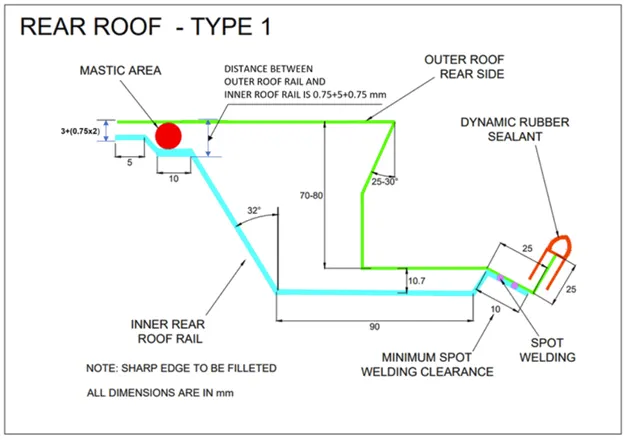
Fig 12 – Rear Roof Rail, and Outer Roof Panel Rear Extension
Front Roof Rail
We designed the front rail as per the Master Section, and added Embosses for Strength as well as to attach lighting and other parts and components, and also added holes for component attachment.
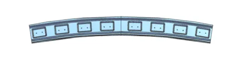
Fig 13a - Top View
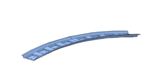
Fig 13b – Isometric View
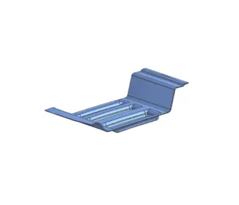
Fig 13c – Side View
Center Roof Rail View-
At 88mm wide, versus 72mm for the Bow Roof Rails, the center reinforcement rail is the widest of our three central reinforcement rails in the roof structure. It contains holes and a slot for mounting lighting and other components. It also has flanges for Mastic application.
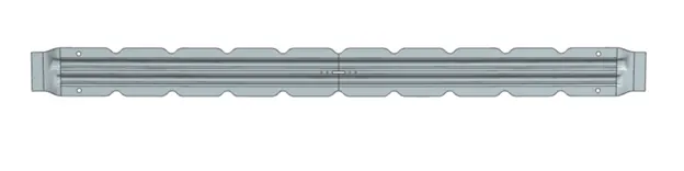
Fig 14a - Top View
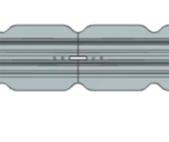
Fig 14b – Center section with Slot and Holes
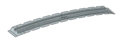
Fig 14c – Isometric View
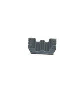
Fig 14d – Side View
Front Bow Roof Rail
The front bow roof rail has tabbed flanges for mastic sealant application.

Fig 15a - Top View
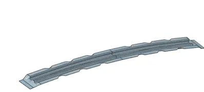
Fig 15b – Isometric View
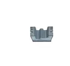
Fig 15c – Side View
Rear Bow Roof Rail
The rear bow roof is similar to the front, with slightly different notching for Mastic Seal application.

Fig 16a - Top View
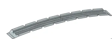
Fig 16b – Isometric View
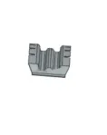
Fig 16a – Side View
Rear Roof Rail View
The rear roof rail contains numerous flanges for rear door attachment. It also has large embosses to provide strength, and slots to reduce weight and absorb rear impact.
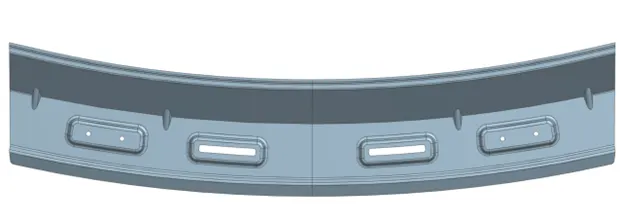
Fig 17a - Top View
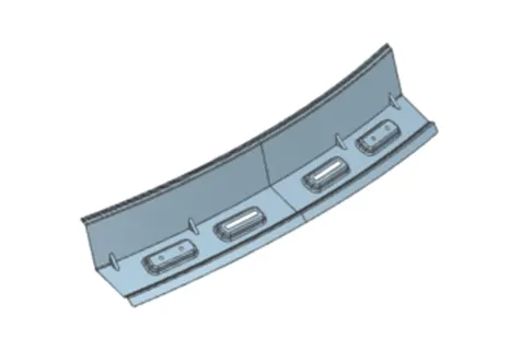
Fig 17b – Isometric View
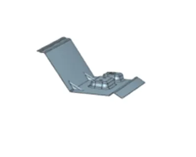
Fig 17c – Side View
Roof Rails Position
In our final design, the three central rails are positioned from the mid-section of the roof to the rear. As the front of the roof has larger curvature, it is is stronger and thus should require less support than the flatter rear section of the roof.
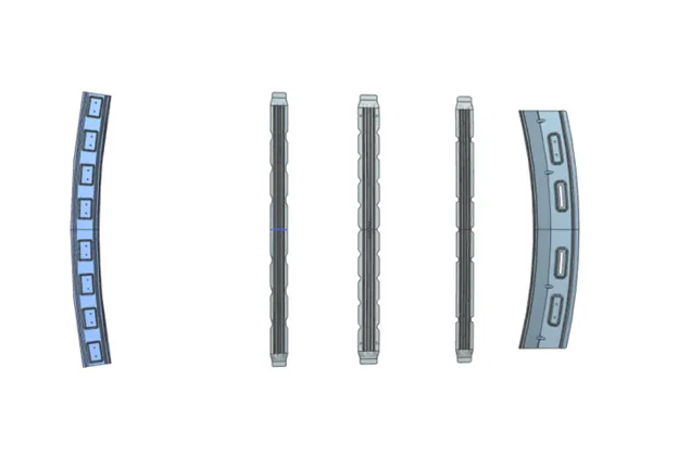
Fig 18a – Rail structure – Top View
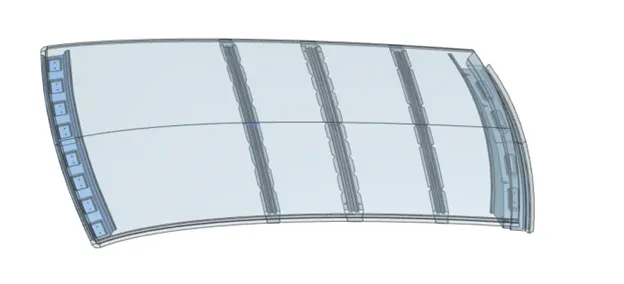
Fig 18b – Rail structure – Isometric View with Translucent Roof
Outer Roof Panel Flanges
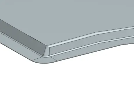
Fig 19a – Outer Roof Panel Flange
Outer Roof Panel Rear Extension
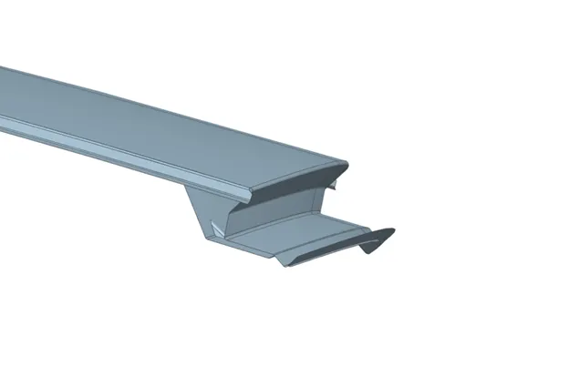
Fig 19b – Outer Roof Panel Rear Extension
Corner relief where the rear extension meets the roof ditch area side flanges.
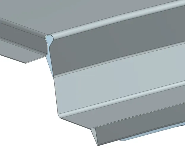
Fig 19c – Corner Relief on Rear Extension
The rear extension will help support the rear door hinges.
Complete Assembly View
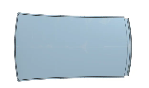
Fig 20a – Top View
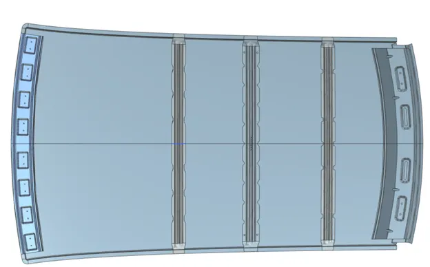
Fig 20b - Bottom View
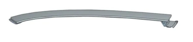
Fig 20c – Side View
Subsequent to completing the roof design, we performed calculations to verify the strength and durability of the Roof. In particular, we conducted a Heat Distortion Study, and a Snow Load Study. In each of these studies, we performed two sets of analysis: one with the reinforcement rails shifted forward, and one with the reinforcement rails shifted back to support the flatter area to the rear of the roof. The results of the studies suggest that the position of the reinforcement rails is not a critical factor in providing for resistance to Heat Distortion and Snow Loading.
Heat Distortion Calculation
We used the following Heat Distortion Calculation as given:
W = [1.73 x 10⁻³ x L] + [1.85 x 10⁻⁸ x (R2)/t] + [ 1.10x10⁻³ x l] - 2.68
Judgement Condition : OK< 2.7> 3.1
Where
L = Roof Length in X-Direction[mm](Roof dimension in 0-Y)
R = Roof curvature
R = 2(Rx*Ry)/(Rx+Ry)
Rx = X curvature
Ry = Y curvature
t = Roof plate thickness [mm]
l = Bow Roof Span [mm]
To determine Rx and Ry we created a sketch to measure these curvature values-
- We created the sketch on the Top Plane of the Roof
- We created a 0Y line along the x-axis in the center of roof
- We offset the 0Y line by 300mm to create a parallel horizontal line below the 0-Y line (-3Y line)
- We added two lines on both sides of the -3Y line, at 100mm offsets
- We created vertical lines running through the mid-point of the sections between each consecutive pairs of rails.
- We offset these vertical lines by 100mm on either side, to create a “grid” pattern.
- We added intersection points at the vertices of the grid.
- We projected the sketch points onto the roof surface, and then created “X” or “+” arcs on the surface to measure the curvature (Rx and Ry)
Case I
(Rails shifted forward)
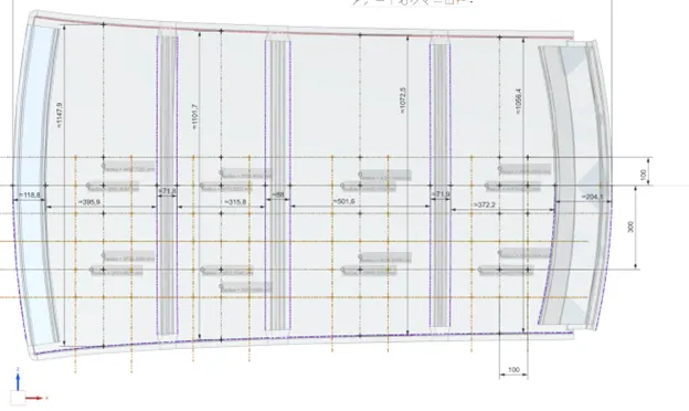
Fig 21a – Sketch for Heat Distortion and Snow Load tests, Case I
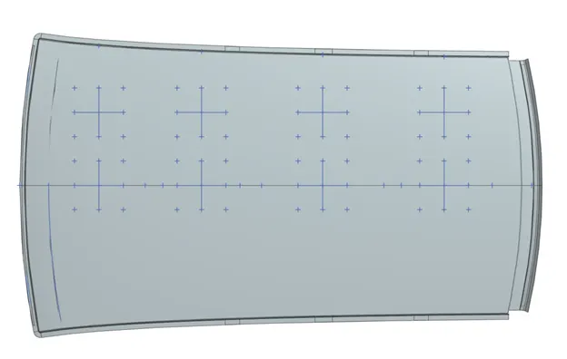
Fig 21b – Projection onto Roof
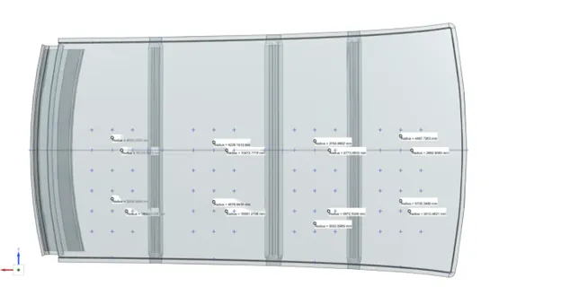
Fig 21c – Curvature Analysis Results shown
Case II (Rails shifted rearward)
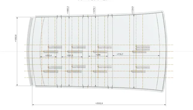
Fig 22a - Sketch for Heat Distortion and Snow Load tests, Case II
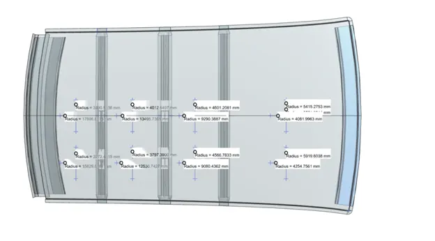
Fig 22b - Curvature Analysis Results shown on the model above
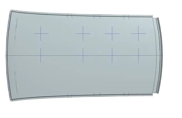
Fig 22c – Projected curves used to calculate curvature
Study Results
Case I

Case II

As the Judgement Condition is: OK< 2.7, all of the values obtained met the Judgement Condition.
Snow Load Calculation
In Winter in cold climates, snow can accumulate on the roof. The roof needs to be strong enough to hold the load, and regain its curvature when the snow is cleared.
Snow load Prediction formula
Qr = [Iy x t2] / [α x s x [(Rx + Ry)/2]2 x 10-8]
Where
α = My x Lx2 x 10-12 , My = Y(Ly-Y)
Judgement condition = Qr ≥ 3.1
250 ≤ s ≤ 380
t = Roof plate thickness [mm]
Ly = Distance between the front and rear roof Rails on the Vehicle along with 0Y[mm]
Length of Roof panel with the center point between Roof rail Front /Rear as the front and rear reference point.
Lx = Distance between the Left and Right end of the roof on the Roof BOW [mm]
Width of the roof panel exposed on the surface.
Y = Distance front Front Roof Rail to Roof BOW[mm]
s = Distance for which Roof BOW bears divided load [mm]
s = L1/2 + L2/2
Iy = Geometrical moment of inertia of Roof BOW (Y cross-section )[mm4]
Rx = Lateral direction curvature radius of roof panel Y cross-section on Roof BOW [mm]
Roof panel curvature Radius of the Length Lx in Front view
Ry = Longitudinal Direction curvature radius of the Roof panel X cross-section on Roof BOW [mm]
Roof panel X curvature radius of length s in Side view
To obtain the input values a sketch was created on top of Roof
- The OY line was created in the center of roof, along the X axis, with horizontal offsets of 100mm on either side.
- We created vertical lines midway between each successive pairs of rails.
- We offset vertical lines by 100mm on either side of the midway lines above
- We created intersection points on the grid created above, and projected these points onto the roof surface.
- Using the projected points, we constructed “X: or “+” shaped arcs on the roof surface and used Radius Analysis to measure the curvature of these arcs.
- We took cross-sections of the three central rails, and projected these into sketches, then performed Section Inertia Analysis to obtain the Section Inertia inputs into the Snow Load equation.
The diagrams are as per Figures 22a through 22c above. As with the Heat Distortion analysis, we constructed the same two cases: Case I with rails shifted forward, and Case II with rails shifted towards the flatter rear section of the roof.
Section Inertia Analysis:
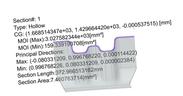
Fig 23a – Section Inertia Analysis, Bow Roof Front
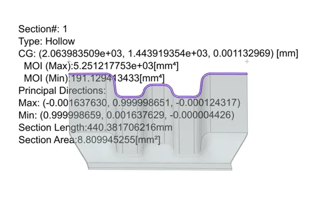
Fig 23b – Section Inertia Analysis, Center Reinforcement Rail
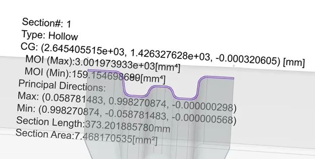
Fig 23c – Section Inertia Analysis, Bow Roof Rear
Snow Load Calculation
Case I

Case II

The Judgement condition is: Qr ≥ 3.1
Based on the Judgement condition, none of the sections in either Case passed. In otherword, whether the rails were shifted forward or rearward made little difference in strengthening the roof in the context of the Snow Load test. As all of the sections failed by a large margin, we suggest the following steps to improve the strength of the roof structure:
- Increase the width of the Bow and Reinforcement rails
- Increase the depth of the Bow and Reinforcement rails
- Add embosses to the roof surface
- Consider doubling the bow roof and reinforcement rails as per the design used for sunroofs.
- Consider adding a third bow roof rail
Draft Analysis
Fore manufacturability, we performed a draft analysis based on a 7 Degree Draft cut-off level (using 6.99 as the actual cut-off, so that a draft of 7-degress will pass).
Front Roof rail
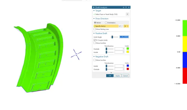
Fig 24a – Draft Analysis, Front Roof Rail
Center Reinforcement Rail
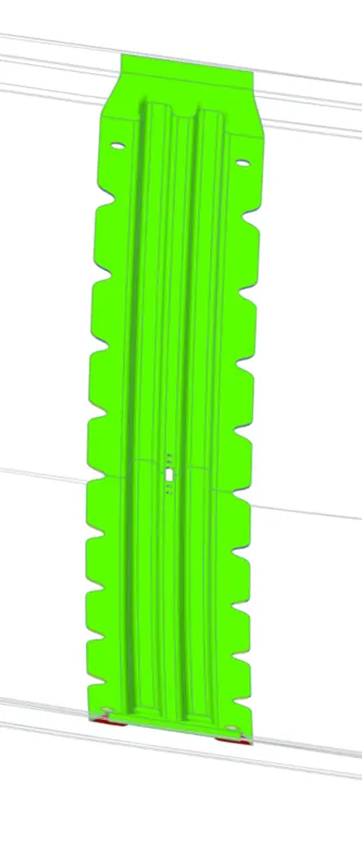
Fig 23b – Draft Analysis, Center Reinforcement Rail
Bow Roof Front
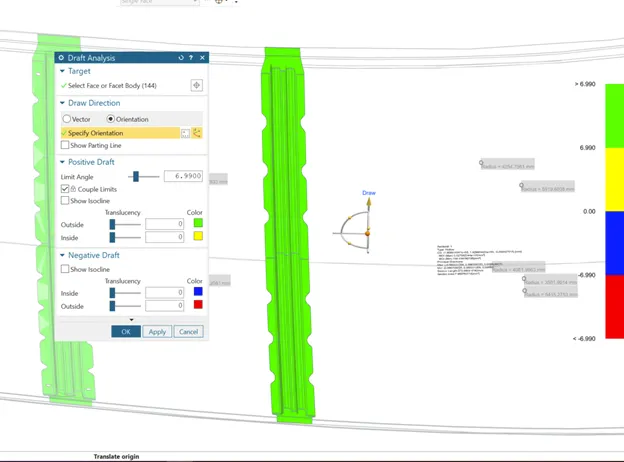
Fig 23c – Draft Analysis, Bow Roof Front
Bow Roof Rear
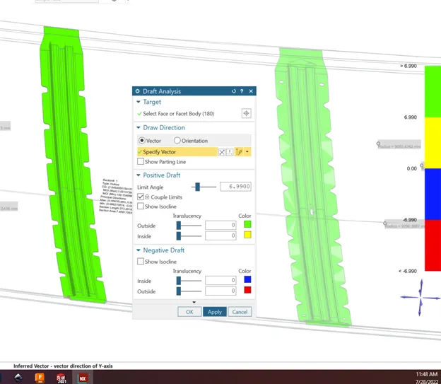
Fig 23d – Draft Analysis, Bow Roof Rear
Rear Roof rail
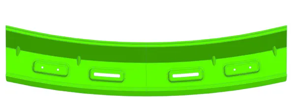
Fig 23e – Draft Analysis, Rear Roof Rail
Outer Panel
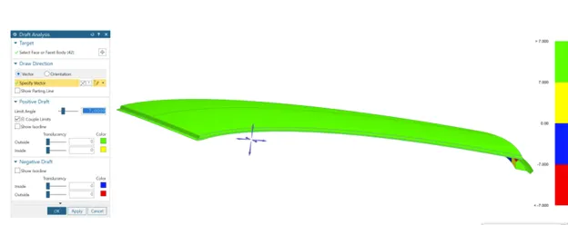
Fig 23f - Draft Analysis, Roof Outer Panel
Additional Views of Roof:
Front View
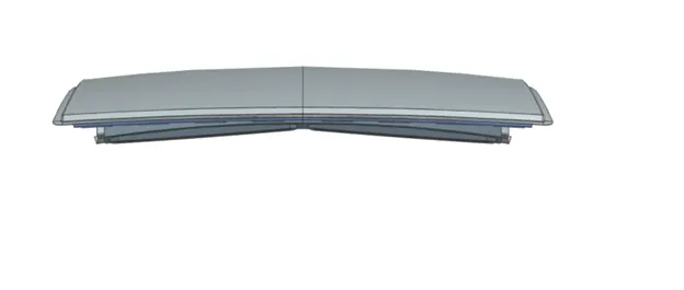
Fig 24a – Roof Front View
Back View
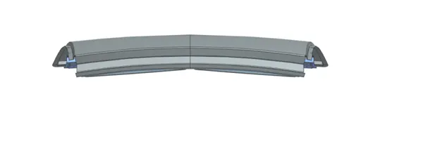
Fig 24b – Roof Rear View
Isometric View
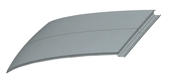
Fig 24c – Roof Isometric View
Side
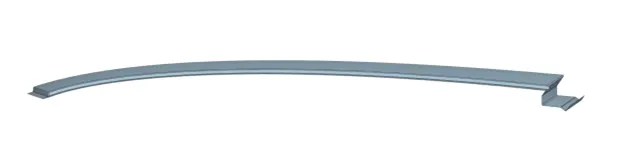
Fig 24d – Roof Side View
Conclusion
We successfully completed the design and testing of the roof structure. The structure as given does not pass the Snow Load test. Colleagues in the Design Department should make suggestions regarding whether the roof should be embossed, and whether the rail structure should be strengthened/improved.