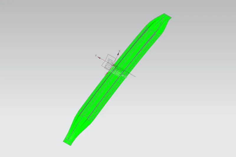
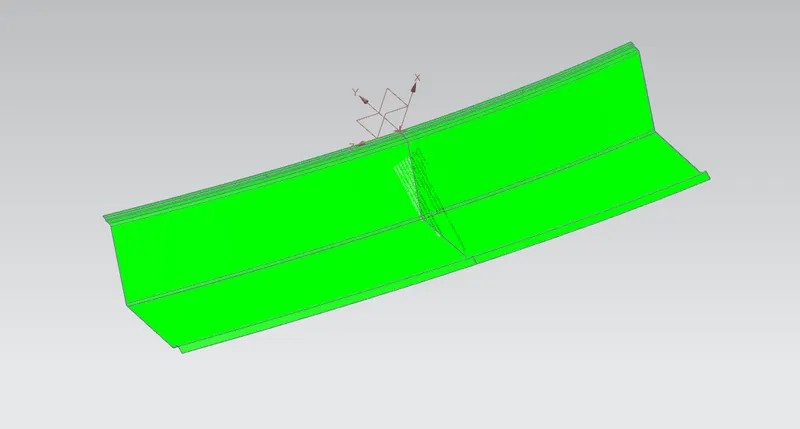
To design and develop the roof of a car with it's components by following the master section and design parameters.
Objectives:
• To develop the essential flanges and reinforcements using roof styling as input.
• To do a curvature study on the roof and perform calculations to determine the position of the Bow-roof.
• To analyze the design roof for Heat Distortion Criteria and Snow Load Criteria of the car's roof.
• To find the section modulus on the O-Y section of the roof and also for all the components of it.
• To perform Draft analysis on the final CAD model of the roof.
Introduction:
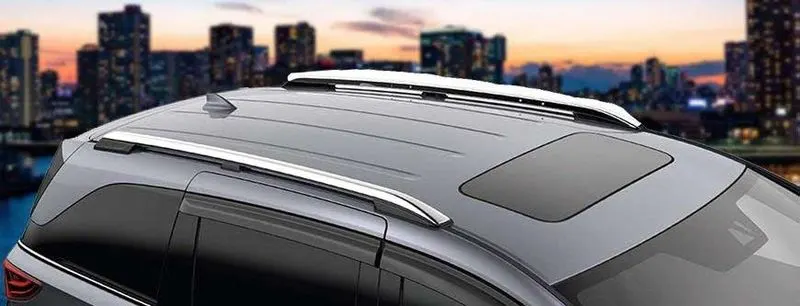
An automobile roof or roof of a car is the top portion of an automobile that sits above the passenger compartment, protecting the vehicle occupants from sun, wind, rain and other external elements.
Fig01: Roof of a car.
Problem Statement:
Design the roof of a car as per given data:
Develop the reinforcements as separate parts.
Start with the creation of a roof ditch area with a tool opening angle of 7 degrees.
Here are some Reference images for the Master sections - These images are just to give you a brief idea about the design.
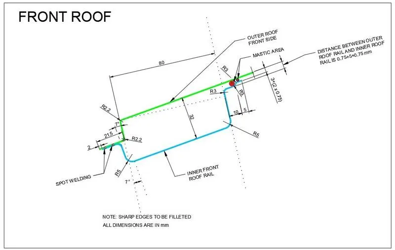
Fig02: Master section of Front Roof Rail.
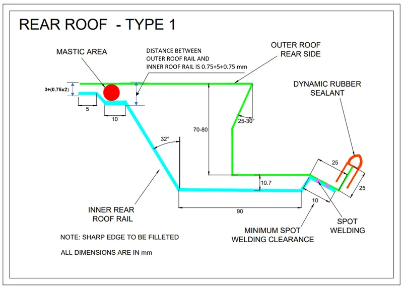
Fig03: Master section of the Rear Roof Rail.
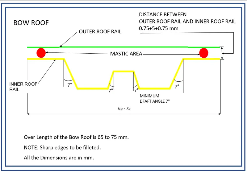
Fig04: Master section of Bow Roof.
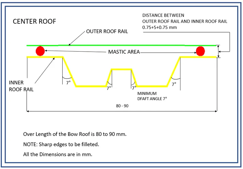
Fig05: Master section of Center Reinforcement Rail.
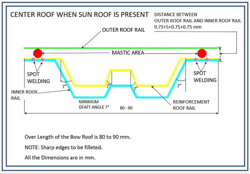
Fig06: Master section of Center Reinforcement Rail when sunroof is present.
Analyze the designed roof for:
I]
Heat Distorsion Prediction Formula
W = [1.73 x 10^(-3) x L] + [1.85 x 10^(-8) x (R^2)/t] + [ 1.10x10^(-3) x l] - 2.68
Where,
L = Roof Length in X-Direction[mm](Roof dimension in 0-Y)
R = Roof curvature
R = 2(Rx*Ry)/(Rx+Ry)
Rx = X curvature
Ry = Y curvature
t = Roof plate thickness [mm]
l = Bow Roof Span [mm]
Judgment Condition
OK< 2.7
II]
Snow Load Prediction Formula
Qr = [Iy x t2] / [α x s x [(Rx + Ry)/2]2 x 10-8]
Note: The Qr value given over here is correct. There was a typo error in the formula given in the video.
Where,
α = My x Lx2 x 10-12 , My = Y(Ly-Y)
t = Roof plate thickness [mm]
Ly = Distance between the front and rear roof Rails on the Vehicle along with 0Y[mm]
Length of Roof panel with the center point between Roof rail Front /Rear as the front and rear reference point.
Lx = Distance between the Left and Right end of the roof on the Roof BOW [mm]
The width of the roof panel is exposed on the surface.
Y = Distance front Front Roof Rail to Roof BOW[mm]
s = Distance for which Roof BOW bears divided load [mm]
s = L1/2 + L2/2
Iy = Geometrical moment of inertia of Roof BOW (Y cross-section )[mm4]
Rx = Lateral direction curvature radius of roof panel Y cross-section on Roof BOW [mm]
Roof panel curvature Radius of the Length Lx in Front view
Ry = Longitudinal Direction curvature radius of the Roof panel X cross-section on Roof BOW [mm]
Roof panel X curvature radius of length s in Side view
Judgment condition
Qr ≥ 3.1
250 ≤ s ≤ 380
Provide appropriate dimensions and check for Draft analysis.
Do a curvature study on the roof and perform calculations to determine the position of the Bow-roofs.
Suggest and implement remedies in the design if the criterion is not full-filling.
Solution:
Design and Calculations:
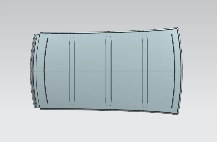
Roof and roof reinforcements are designed in NX CAD from the given styling surface. Sheet thickness is considered as 0.75 mm for all components. Two bow roofs are provided for the strength of the roof.
Fig07: Outer surafce of the roof of a car with the reinforcements.
Front roof rail:
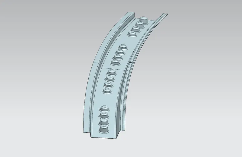
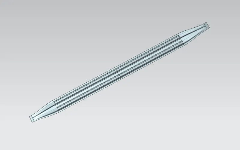
This is the reinforcement provided at front. This part is joined to BIW body and windshield. Visibility criteria is taken in account for joining it with windshield. It is fixed to BIW with spot welds and roof surface is attached with the help of mastic sealants. A draft angle is provided for deep drawing operation. Draft analysis is also done on the section to check it's manufacturing ability.
Fig08: Front roof rail of the roof of a car.
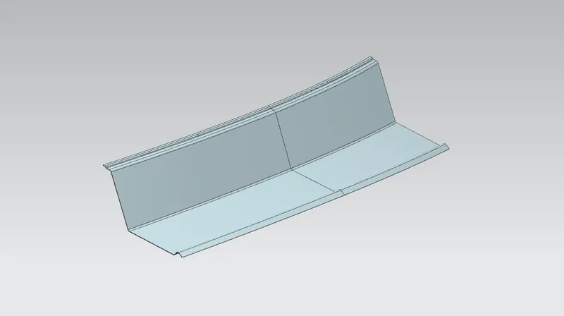
Bow roof rail 1 and 2:
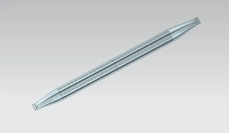
These are additional reinforcements provided to increase the strength of the roof. It is fixed with roof body with mastic sealants.
Fig09: Bow roof rail-1 of the roof of a car.
Fig10: Bow roof rail-2 of the roof of a car.
Centre roof rail:
Centre rail roof can be considered as reinforcement joining the left and right part of the roof. It is fixed to roof by mastic sealants and to BIW by spot welds.
Fig11: Centre roof rail of the roof of a car.
Rear roof rail:
It is the reinforcement provided at rear side of the roof. Backdoor and bodyside panels are attached with this part. It is also attached with mastic sealants and spot welds.
Fig12: Rear roof rail of the roof of a car.
Analysis of roof for heat distorsion criteria:
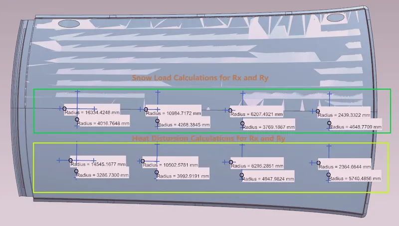
Fig13: Calculations for Rx and Ry of roof rails of the roof of a car.
Fig14: Heat Distorsion calculations for the roof of a car.
Analysis of roof for snow load criteria:
Fig15: Snow Load calculations for the roof of a car.
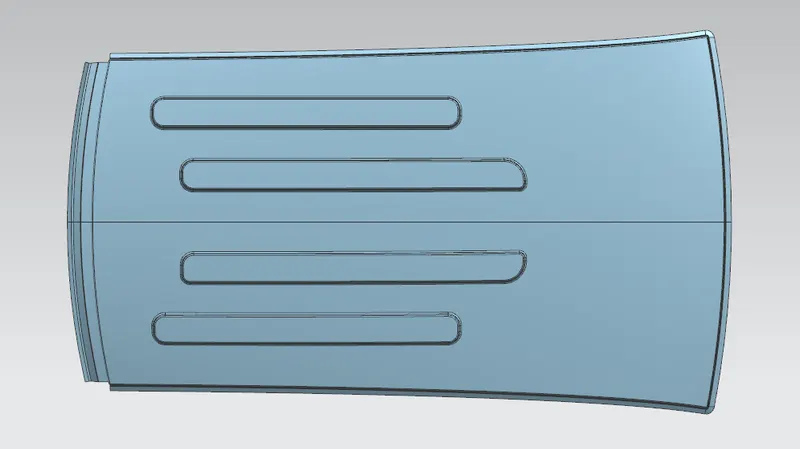
It is observed that the roof is not satisfying the required conditions for snow load criteria between it's adjacent roof rails. So in order to strength the the roof at these areas embosses are created on the outer roof.
Fig15.1: Roof of a car with emobosses.
Section modulus:
Section modulus is a geometric property for a given cross-section used in the design of beams. Other geometric properties used in the design include an area for tension, radius of gyration for compression and moment of inertia for stiffness. The section modulus of cross-sectional shape is of significant importance in designing of structures. It is the direct measure of the strength of the structure.
A structure that has a larger section modulus than other will be stronger and capable of supporting greater loads.
The section modulus is defined as:
`S = frac{I}{y}`
where,
S = Section Modulus.
I = Moment of Inertia.
y = Distance from the neutral axis to any given part.
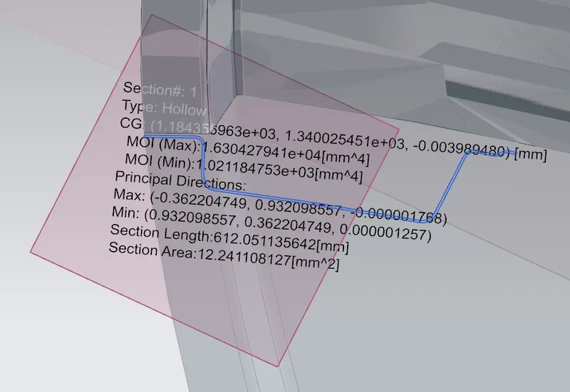
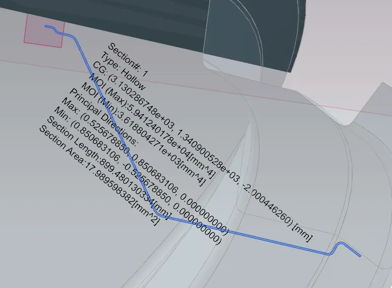
Fig16: Section inertia analysis for front roof rail of a car.
I = 1021.18 mm^4
y = 56.07 mm
S = I/y
S = 18.21 mm^3
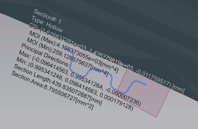
Fig17: Section inertia analysis for bow roof rail-1 of a car.
I = 259.13 mm^4
y = 37.43 mm
S = I/y
S = 6.9 mm^3
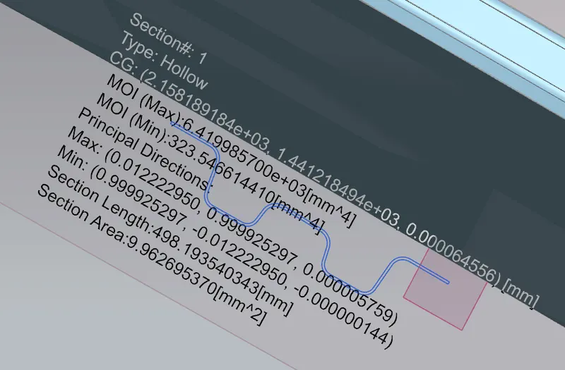
Fig18: Section inertia analysis for centre roof rail of a car.
I = 323.55 mm^4
y = 45 mm
S = I/y
S = 7.19 mm^3
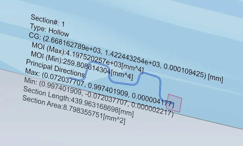
Fig19: Section inertia analysis for bow roof rail-2 of a car.
I = 259.81 mm^4
y = 37.43 mm
S = I/y
S = 6.9 mm^3
Fig20: Section inertia analysis for rear roof rail of a car.
I = 3618.80 mm^4
y = 85.71 mm
S = I/y
S = 42.22 mm^3
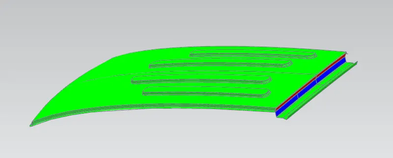
Fig21: Draft analysis for roof of a car.
Here, red portion represents that this part cannot be produced in one GO, therefore we will have to manufacure it in two different parts and then join it with suitable method.
Fig22: Draft analysis for front roof rail of a car.
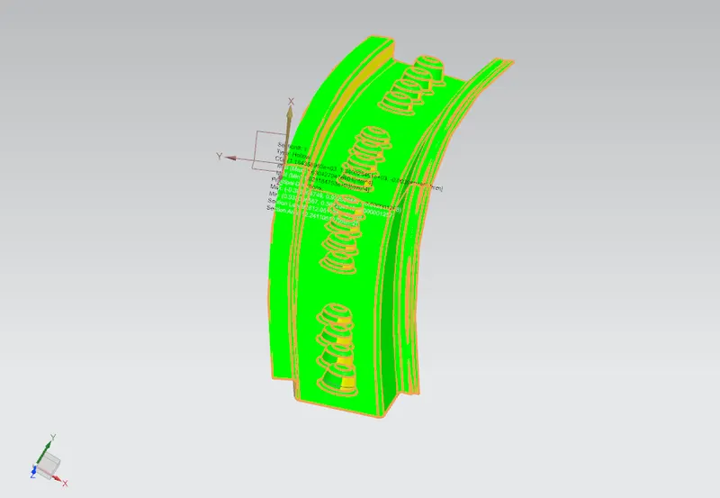
Fig23: Draft analysis for bow roof rail-1 of a car.
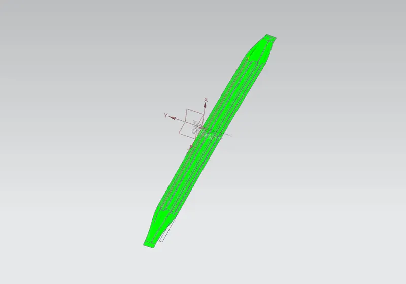
Fig22: Draft analysis for centre roof rail of a car.
Fig22: Draft analysis for rear roof rail of a car.
Conclusion:
We studied the design and analysis of a roof of a car using NX-CAD tool.