Roof Design and Curvature Study
- Project: Roof Design and Curvature Study
- Introduction:
This project report is about 3D modelling a Roof Assembly of automobile and curvature study using Siemens NX 11.
- Objective:
The aim of this Project is to model a Roof Assembly considering all design and safety factors which satisfies industry’s standards, manufacturing & functional requirements and engineering inputs using Siemens NX 11. And also, to study the curvature of roof outer panel.
- Roof Design and Assembly:
A car roof top protects the passengers from sun, rain and other external elements.
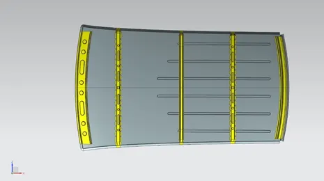
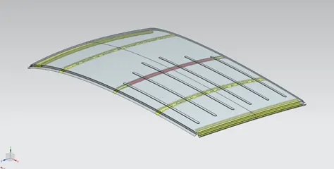
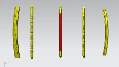
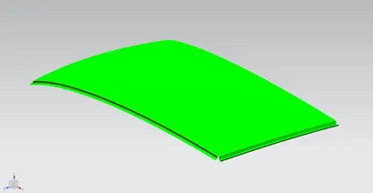
A Roof assembly consist of roof outer panel which is supported by bow roof rails and Front and Rear roof rails.
In this project we will be focusing on designing Fr and Rr roof rails, bow roof rails and ditch area using Siemens NX 11 surface and other tools.
We will also study the roof curvature and bow roof positioning with the help of bow roof prediction formula and snow load prediction formula.
- Commands used:
- Extracted geometry: Creates a associative copies of bodies, surfaces, curves, points etc.
- Offset Surface: This command is used to create a surface by offsetting a set of faces.
- Offset Curve in Face: It is used to offset curves along a selected face or surface.
- Trim Sheet: It is used to cut off a portion of surface.
- Through curves: Creates a surface through multiple sections where the shape changes to pass through each section.
- Studio Surface: Creates a surface using any number of section and guide strings.
- Face blend: Add tangent blend faces between selected set of faces with specified radius.
- Projected curve: Using this command we can project curves, sketch or points on to the selected face or plane.
- Law Extension: It creates a law-controlled extension from base sheet, dynamically or based on laws for distance and angle.
- Extend Sheet: Extends the sheet body by distance or to the intersection with another body.
- Edge blend: Rounds the sharp edges of the faces with specified radius.
- Emboss: This command modifies the surface by projecting a section along a vector, with options for end cap location and shape.
- Curve on Surface: It used for sketching a spline on face or surface.
- Mirror Geometry: Copies the geometry and mirrors them across a plane.
- Sew: Sew is used to combine sheet bodies by sewing their edges together.
- Thicken: It gives thickness to the surface body.
- Draft Analysis:
This tool helps us to analyze the back-draft condition of the model.
- Roof:
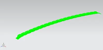
- Front Roof Rail:
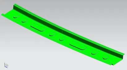
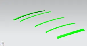
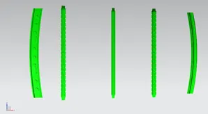
- Front Bow Roof Rail:
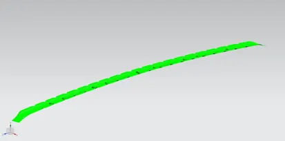
- Centre Bow Roof Rail:
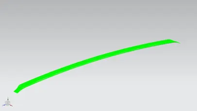
- Centre Bow Roof Reinforcement:
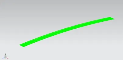
- Rear Bow Roof Rail:
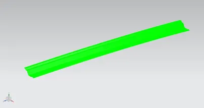
- Rear Roof Rail:
- Section Modulus Calculation:
Section Modulus is a geometric property for a given cross-section area used in structural engineering design. There are two types section modulus called Elastic section modulus and Plastic section modulus.
In this report we are discussing about Plastic section modulus.
Plastic Section Modulus Equation:
S=I/y, where
S= Elastic Modulus
I = second moment of sectional area
y= distance from neutral axis to extreme end of the object
- Roof:
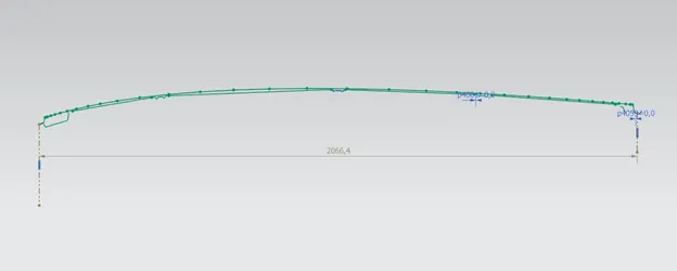
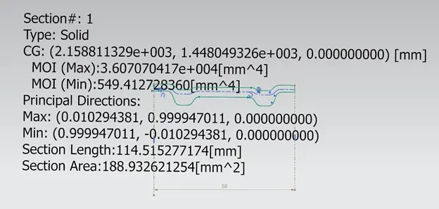
I = 1.8404 x 107 mm4
Y = 1033.2 mm
S = 17.80931x103 mm3
- Front Roof Rail:
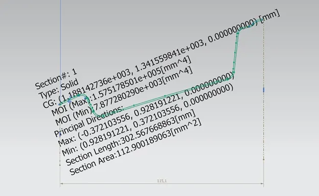
I = 7.8773 x 103 mm4
Y = 57.55 mm
S = 136.87 mm3
- Front Bow Roof Rail
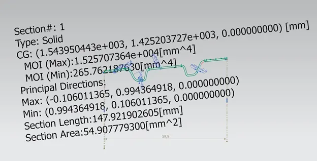
I = 265.7621 mm4
Y = 29.9 mm
S = 8.888 mm3
- Centre Bow Roof Rail with Reinforcement:
I = 549.4127 mm4
Y = 25 mm
S = 21.99 mm3
- Rear Bow Roof Rail:
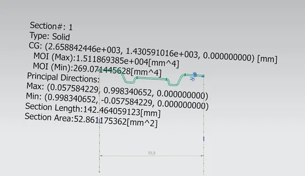
I = 269.0714 mm4
Y = 29.9 mm
S = 8.99 mm3
- Rear Roof Rail:
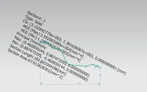
I = 1.1957 x 103 mm4
Y = 37.25 mm
S = 32.099 mm3
- Curvature Study (Bow Rail Positioning Prediction):
The curvature study analysis helps us to determine and validate the positioning of the bow roof rails.
The study is done using below two criteria:
- Heat Distortion Criteria:
- Snow load Criteria:
- Bow – Roof prediction Formula:
W = [1.73 x 10⁻³ x L] + [1.85 x 10⁻⁸ x (R2)/t] + [ 1.10x10⁻³ x l] - 2.68
Judgement Condition: OK< 2.7> 3.1
Where
L = Roof Length in X-Direction[mm] (Roof dimension in 0-Y)
R = Roof curvature
R = 2(Rx x Ry) / (Rx + Ry)
Rx = X curvature
Ry = Y curvature
t = Roof plate thickness [mm]
l = Bow Roof Span [mm]

- Snow load Prediction formula:
Qr = [Iy x t2] / [α x s x [(Rx + Ry)/2]2 x 10-8]
Where
α = My x Lx2 x 10-12 & My = Y(Ly-Y)
Judgement condition = Qr ≥ 3.1
250 ≤ s ≤ 380
t = Roof plate thickness [mm]
Ly = Distance between the front and rear roof Rails on the Vehicle along with 0Y[mm]
Length of Roof panel with the center point between Roof rail Front /Rear as the reference point of the front and the rear.
Lx = Distance between the Left and Right end of the roof on the Roof BOW [mm]
Width of the roof panel exposed on the surface.
Y = Distance from Front Roof Rail to Roof BOW [mm]
s = Distance for which Roof BOW bears divided load [mm]
s = L1/2 + L2/2
Iy = Geometrical moment of inertia of Roof BOW (Y cross-section) [mm4]
Rx = Lateral direction curvature radius of roof panel Y cross-section on Roof BOW [mm]
Roof panel curvature Radius of the Length Lx in Front view
Ry = Longitudinal Direction curvature radius of the Roof panel X cross-section on Roof BOW [mm]
Roof panel X curvature radius of length s in Side view

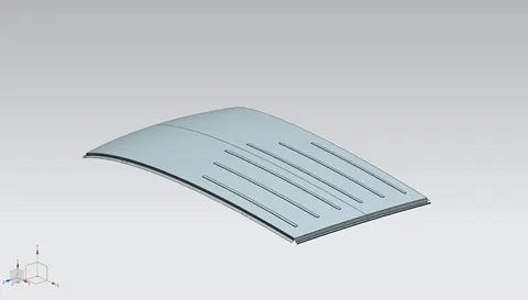
For this roof design, from snow load formula we get to know that the curvature of roof from mid to rear section is Not Good therefore we have to make some changes in the roof design.
We can change the position of bow roof rail or can add one more bow roof rail or we can add embosses on the roof outer skin to increase the strength.
I have added embosses on the roof outer skin.
Conclusion:
From this excersize, I have learned how to approach the Roof Design using Siemens NX 11.