Roof challenge
ROOF
What is a Roof?
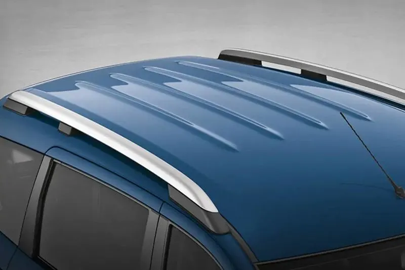
- It is an automobile roof which is a BIW portion of an automobile that sits above the passengers compartment and protecting the vehicle occupants from sun,rain,wind and other external elements.
DESIGN CONSIDERATIONS
1. Visibility Criteria: This should be followed while creating the front flange and it should provide proper support to wind shield and also provide proper visibility to the customer.
2. Head Clearence:The measurement of “headroom” is the distance from a vehicle's roof to its seat bottom.
3. Heat Distortion and Snow Distortion: These calculations and consdieration are done according to the climatic condition of the country the consumer is going to use the vehicle.
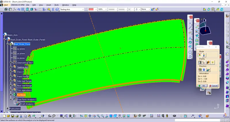
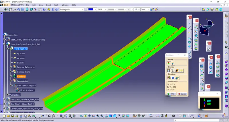
4. Draft Analyisis: This analysis is done on the finished product to check whether the whole product is following draft conditions or not.
There are two types of RollOvers:
1. Tripped-NHTSA data show that 95% of single-vehicle rollovers are tripped. This happens when a vehicle leaves the roadway and slides sideways, digging its tires into soft soil or striking an object such as a curb or guardrail. The high tripping force applied to the tires in these situations can cause the vehicle to roll over. E.g. Soft soil, Guardrail, Steep Slope
2. Un-Tripped -Un-tripped rollovers are less common than tripped rollovers, occurring less than 5% of the time, and mostly to top-heavy vehicles. Instead of an object serving as a tripping mechanism, un-tripped rollovers usually occur during high-speed collision avoidance manoeuvres.
Inputs provided by styling team are:
1. Front Roof.
2. Rear Roof.
3. Center Roof Rail.
4. Bow Roof Rail.
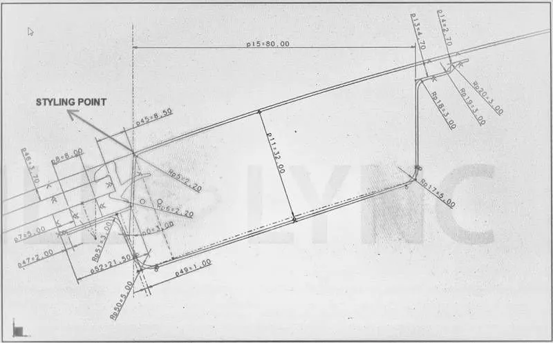
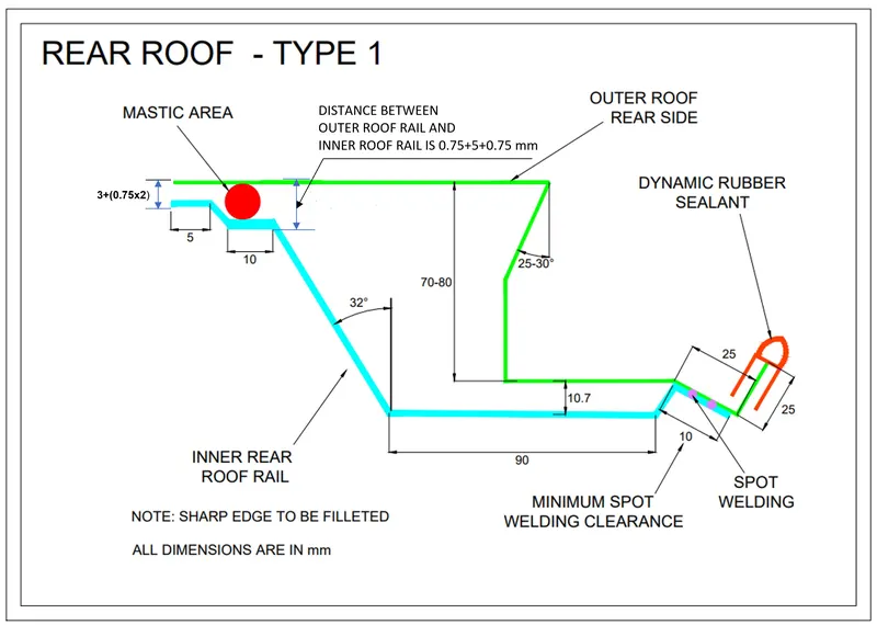
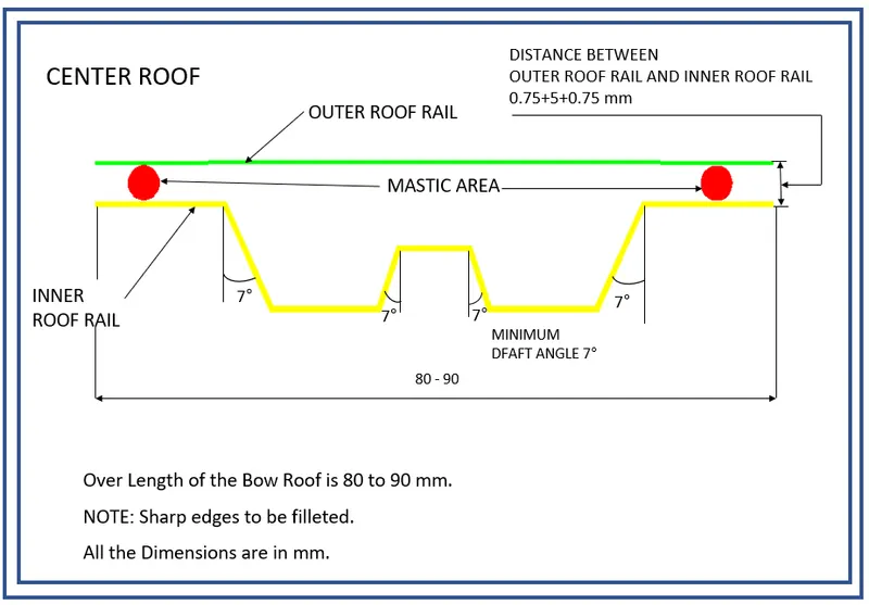
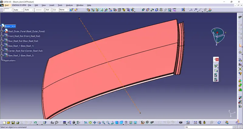
Roof Ditch Area: This is the aesthetic part of the vehicle which is visible to human eye. This is the top most part of the vehicle. The design of roof is done using the master sketch given giving appropriate draft angle for sheet metal production. To design this we had used front roof and rear roof master section.
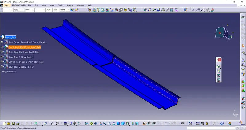
Front Rail: This is the part that connects the roof ditch panel to the A-pillar of the car. Except for the roof panel all other parts provides strengthening aids to the roof panel. The Front rail is welded to the A pillar and the roof panel. The front rail comes in the front part of the vehicle.
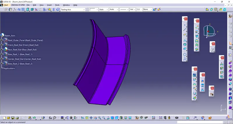
Rear Rail: This part connects the roof panel to the rear pillar. This part is designed as per the opening of the rear door of the Vehicle. The design is done as per the master sections provided.
Center Roof Rail: The centre reinforcement is given to add more stiffness to the roof. It helps in increasing the load-carrying capacity of the roof and resists to deformation caused due to any snow settling over the roof.
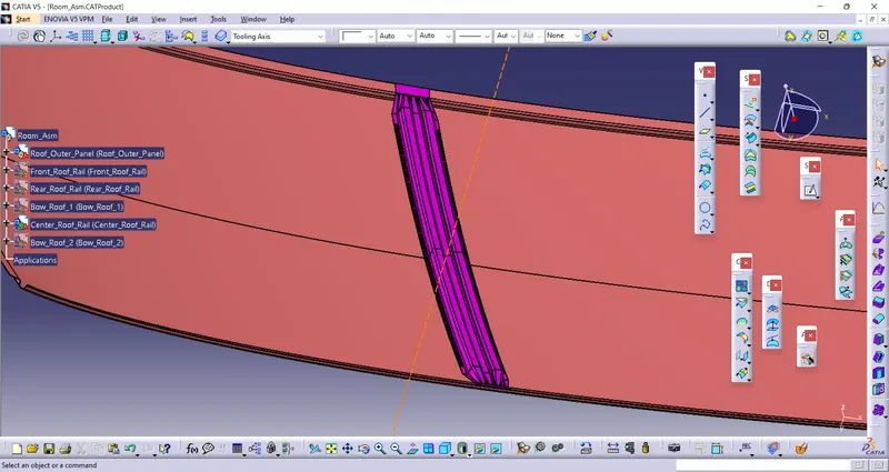
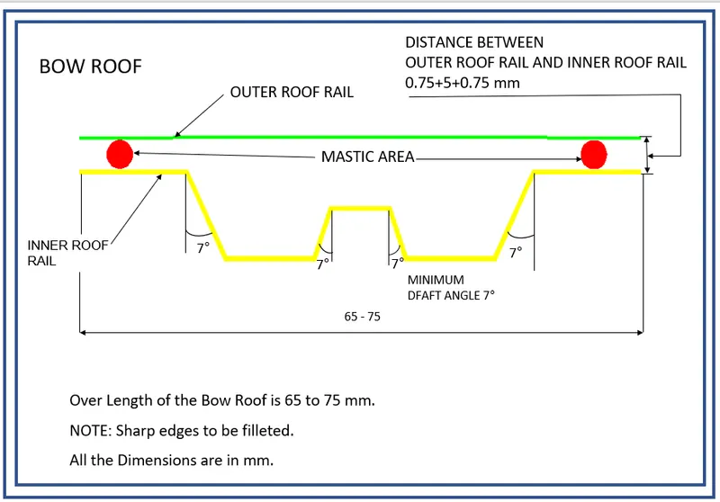
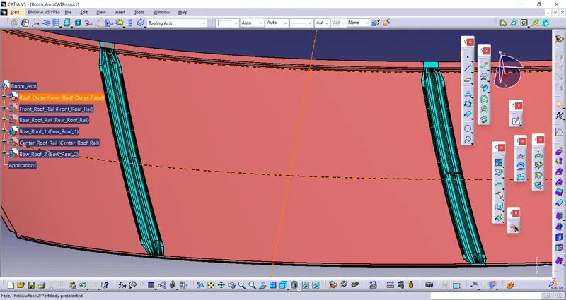
Bow Roof Rail: These parts are added to increase the load-carrying capacity of the roof of the car. Three bow roofs are designed for our project.
DRAFT ANALYSIS
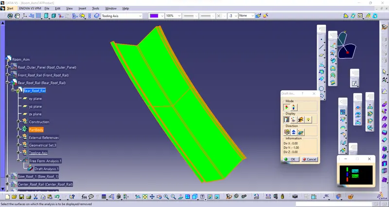
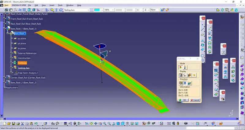
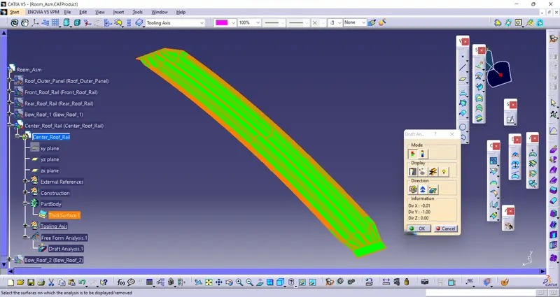
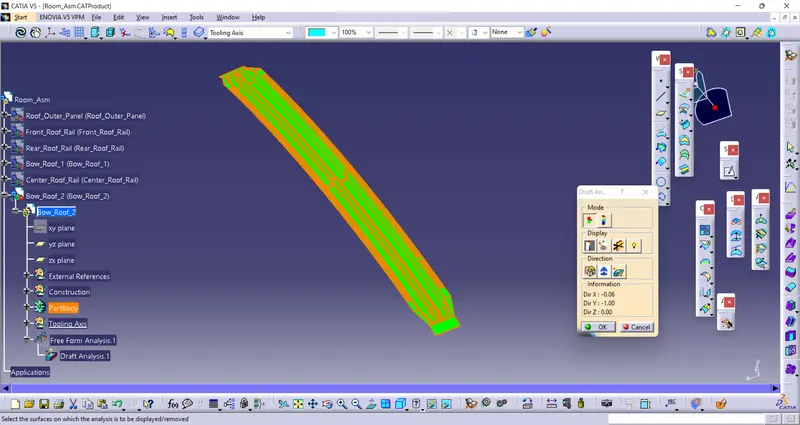
Heat Distortion Analysis
The location of the bow roof and reinforcements are determined prior to the start of design. This helps in reducing the work of analysis engineer for crash and snow load tests. All the values are created based on the formula given below.
Formula:
W = [1.73 x 10^(-3) x L] + [1.85 x 10^(-8) x (R^2)/t] + [ 1.10x10^(-3) x l] - 2.68
Judgement Condition : W< 2.7
Where
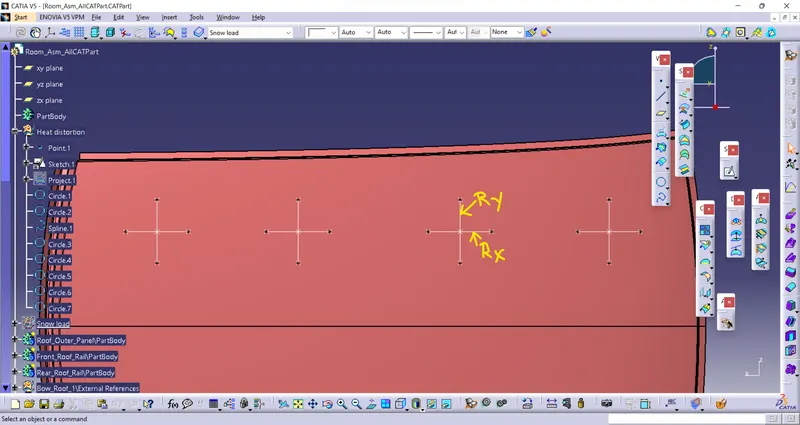
L = Roof Length in X-Direction[mm](Roof dimension in 0-Y)
R = Roof curvature
R = 2(Rx*Ry)/(Rx+Ry)
Rx = X curvature
Ry = Y curvature
t = Roof plate thickness [mm]
l = Bow Roof Span [mm]
|
CASES |
L |
Rx |
Ry |
t |
l |
W |
W<2.7 |
|
FRR-BR1 |
2115.653 |
1830.636 |
5739.268 |
0.75 |
382.036 |
1.59 |
OK |
|
BR1-CRR |
2115.653 |
3206.673 |
4974.78 |
0.75 |
425.087 |
1.82 |
OK |
|
CRR-BR2 |
2115.653 |
4086.245 |
3978.36 |
0.75 |
424.837 |
1.84 |
OK |
|
BR2-RRR |
2115.653 |
4569.346 |
3299.345 |
0.75 |
330.418 |
1.705 |
OK |
Snow Load Analysis
Qr = [Iy x t2] / [α x s x [(Rx + Ry)/2]2 x 10-8]
Where
α = My x Lx2 x 10-12 , My = Y(Ly-Y)
Judgement condition = Qr ≥ 3.1
t = Roof plate thickness [mm]
Ly = Distance between the front and rear roof Rails on the Vehicle along with 0Y[mm]
Length of Roof panel with the centre point between Roof rail Front /Rear as the front and rear reference point.
Lx = Distance between the Left and Right end of the roof on the Roof BOW [mm]
( Width of the roof panel exposed on the surface.)
Y = Distance front Front Roof Rail to Roof BOW[mm]
s = Distance for which Roof BOW bears divided load [mm]
s = L1/2 + L2/2
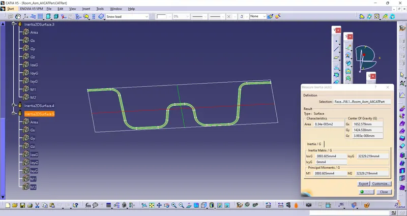
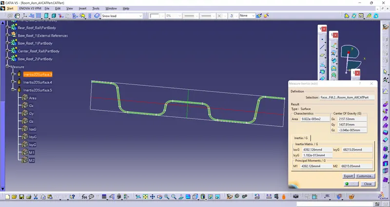
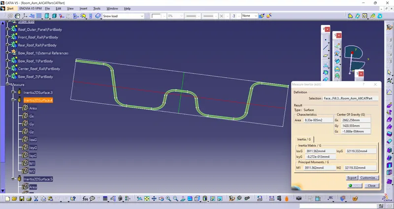
Iy = Geometrical moment of inertia of Roof BOW (Y cross-section )[mm4]
Rx = Lateral direction curvature radius of roof panel Y cross-section on Roof BOW [mm]
Roof panel curvature Radius of the Length Lx in Front view
Ry = Longitudinal Direction curvature radius of the Roof panel X cross-section on Roof BOW [mm]
Roof panel X curvature radius of length s in Side view
Section Modulus
1. Bow Roof 1
2. Center rail roof
3. Bow Roof 2
|
CASES |
IY |
t |
α |
Lx |
Ly |
My |
Rx |
Ry |
|
FRR-BR1 |
3893.605 |
0.75 |
0.9709 |
1116.502 |
2115.653 |
778903.24 |
1863.765 |
4555.021 |
|
BR1-CRR |
4392.126 |
0.75 |
0.9459 |
1078.37 |
2115.653 |
813493.63 |
3184.848 |
3763.334 |
|
CRR-BR2 |
3911.562 |
0.75 |
0.9137 |
1060.059 |
2115.653 |
813170.76 |
4164.854 |
4274.07 |
|
BR2-RRR |
- |
0.75 |
0.8489 |
- |
2115.653 |
755506.68 |
4740.801 |
4036.808 |
|
L1 |
L2 |
S |
Y |
Qr |
|
474.651 |
505.103 |
489.877 |
474.651 |
44.706 |
|
505.103 |
504.811 |
504.957 |
505.103 |
42.856 |
|
504.811 |
454.925 |
479.868 |
504.811 |
28.18 |
|
454.925 |
- |
227.462 |
454.925 |
- |
CONCLUSION: We developed Roof with front rail, rear rail, center roof rail and Bow roof rail with the provided master section and also followed with draft analysis and did calculation for Heat distortion and Snow Load Distortion for the roof stiffness.