Roof challenge
DESIGN OF ROOF
1. Objective-: The main aim of this project is to design the flanges, reinforcements and bow roof from the given roof Class-A surface.
- To perform the case study for Heat distortion & Snow load.
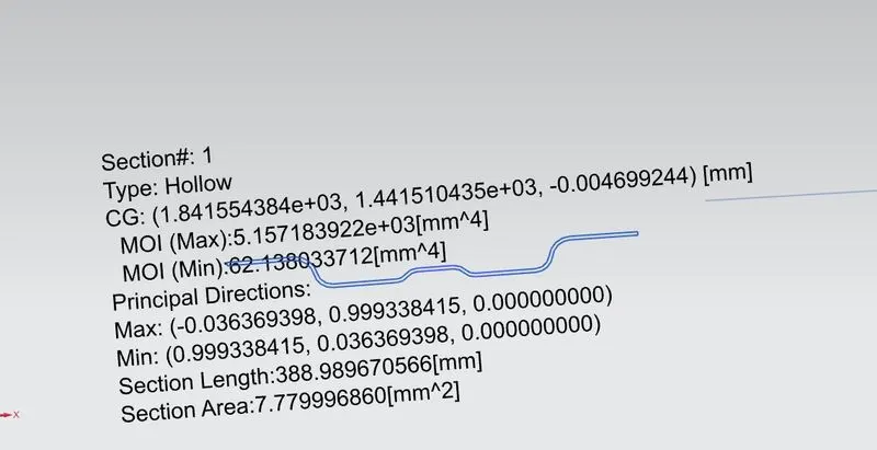
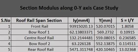
- To calculate Section modulus of each reinforcement & rails along Y axis.
- To perform draft analysis & submit detailed report.
2. Introduction-: A vehicle roof is an essential and major component that plays an essential role in vehicle body. This part/compartment is situated at the top of vehicle body. Roof function is to protect & prevent car passengers from sunlight, rain, dust, wind. Roof not only shields guard the vehicle from environmental factors but also provide an aesthetic as well as appealing appearance.
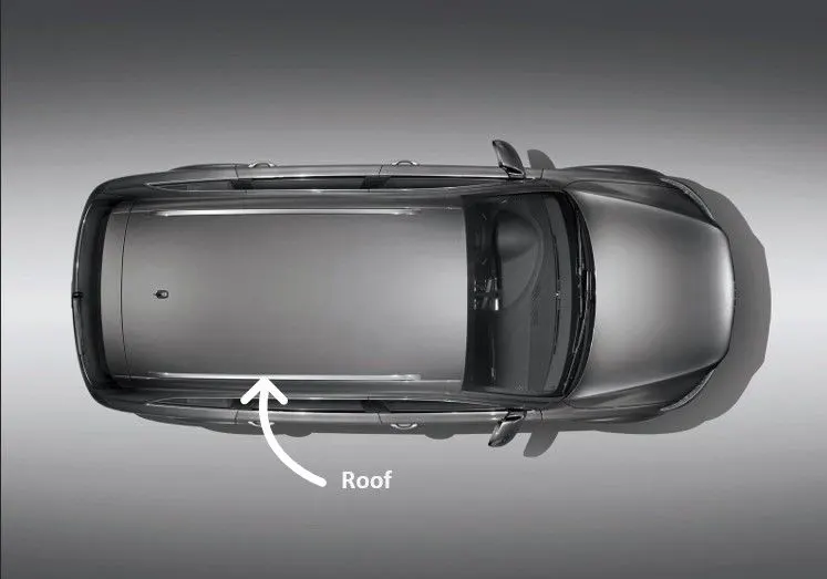
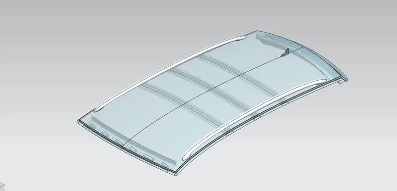
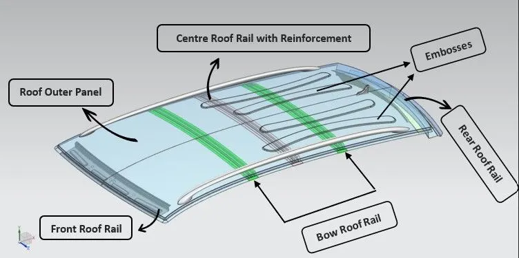
Roof is designed from the Class-A surface & master sketch shared with us. Roof is designed with following considerations - styling, aesthetic as well as an, safety standards, driver viewing angle. The roof is designed as an assembly with the following components-:
- Front Roof Rail.
- Rear Roof Rail.
- Bow Roof Rails.
- Centre Roof Rail with reinforcement.
- Ditch Area.
Significance of Car roof-:
Provide safety from environmental weather factors and atmosphere.
- To prevent from accidental drops & external damage if any.
- Provides car an aesthetic appearance & durability to vehicle structure.
- Can be used as the luggage carrier along with roof rails.
Types of Car roof-:
The vehicle roof determines and appeals a lot about it. It depicts the use of vehicle, its segment, the community of people who will buy it, the region for which car is designed.
There are various types of car roofs based on its segment and appearances-:
a. Hardtops-: These types of roofs are seen in modern day usage cars. They are built up of metal.
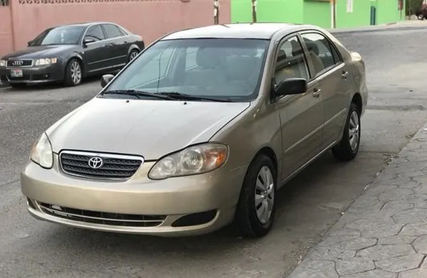
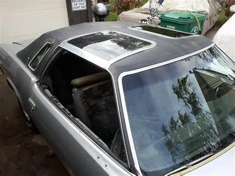
b. Sunroof-: These types of roofs are more common now a days. These types of roofs are operatable roofs that can be opened and closed manually or automatically. Roof contains a section that is of window form that can be opened or closed. The types of sunroofs are-:
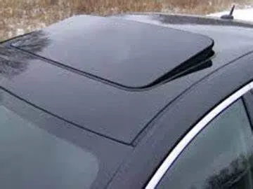
i. Pop-Up Sunroof-: The pop-up sunroofs tilts when you open it. These sunroofs are common and cheap. The sunroof can be removed in some cases and kept in trunk for usage.
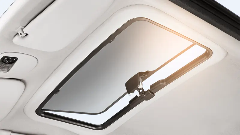
ii. Spoiler Sunroof-: These roofs are slide type of sunroofs and can be slide to open and close.
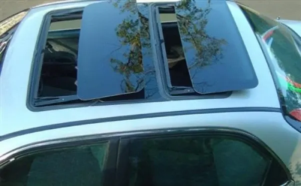
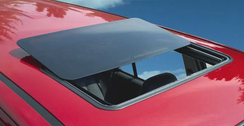
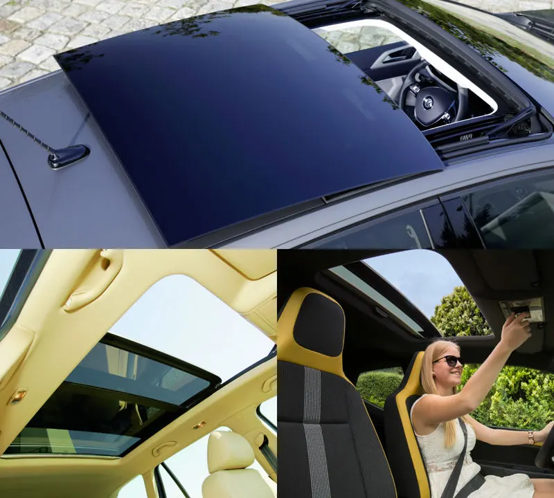
iii. Panoramic Sunroof or Moonroofs-: These roofs are known as Panoramic sunroof or also as moonroofs. These are operated automatically and are also provide as front and rear sunroofs.
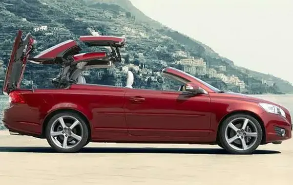
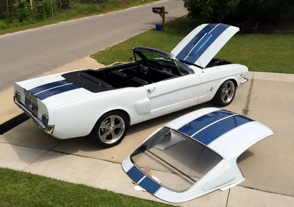
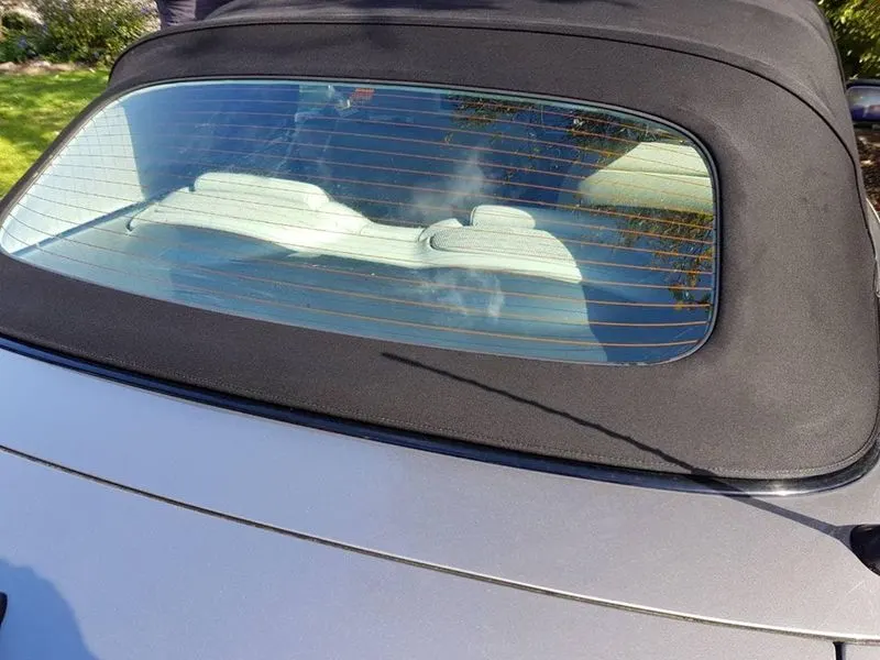
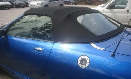
iv. Convertibles-: The Convertibles vehicles are also known as Open roof vehicles. These are the roofs that can be folded and retract on its trajectory. The types of convertible roofs are-:
a. Retractable hardtops-:
b. Detachable Hardtops-:
c. Soft Tops-:
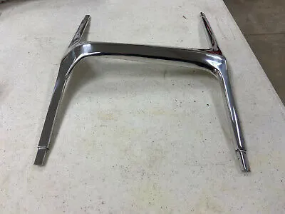
d. T-Tops-:
4. Manufacturing practices for roof-:
a. Stamping -: Stamping is the process of getting aa desired shape out of a piece of sheet metal. In this process the sheet metal is blanked into the desired size and then drawn into a desired shape using die. The draft angle is taken into consideration for part producibility at which the part is drawn.
Then the part is trimmed for unwanted parts and heat treated for improving the strength and the required thickness. This whole process is known as stamping.
b. Assembly-: In this process the sheet metal parts and components are joined and assembled into the required shape by welding process. The welding processes used for joining sheet metal parts are –
- TIG Welding.
- MIG Welding.
- Fused arc welding.
- Spot welding or robot welding.
- Fibre Laser Welding.
c. Washing & Painting-: Then the assembled part is washed on a jet spray or shower line for impurities and unwanted dust particles from the part surface. The part is inspected physically for any unwanted area or for bad weld seam. Then the part is marked ok and supplied to paint line for painting process.
5. Designing of Roof-:
For designing of roof, we need some inputs such as front & rear visibility criteria, driver seat position, & a Class-A surface from styling team. Then later the flanges, reinforcements and inner roof rails are designed from the following inputs. The considerations required for designing a hood is-:
- Head clearance.
- Class-A surface.
- Visibility criteria.
- Master Section for reinforcements & inner roof rail.
- Section modulus case study for inner roof rails & reinforcements.
- Draft Analysis for part producibility analysis.
- Safety Procedures.
Design Considerations-:
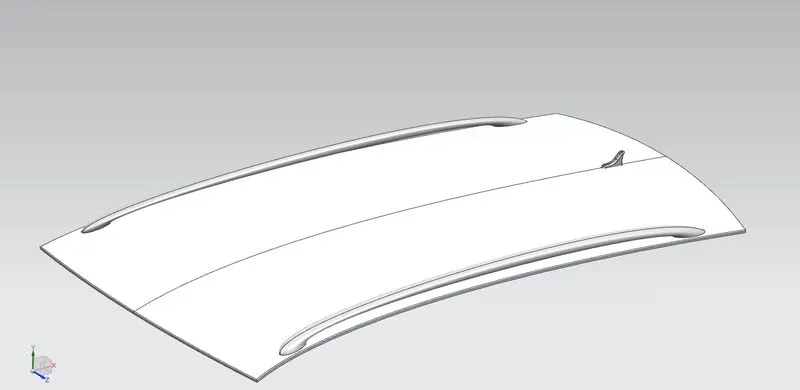
i. Styling surface/Class-A surface-: The outer surface which has aesthetic appearance & is aerodynamic. According to this surface we will design the entire roof part.
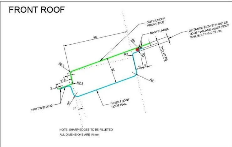
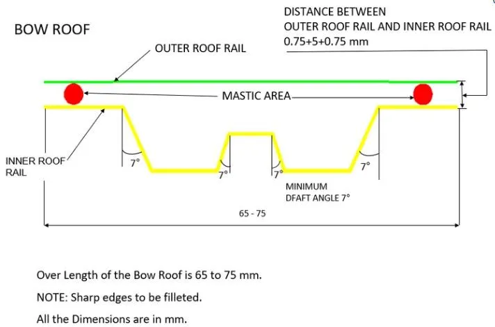
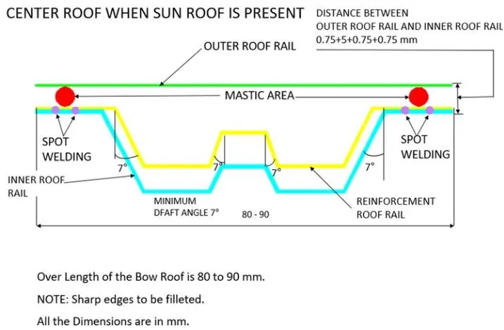
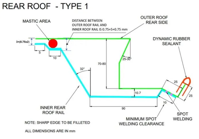
ii. Master Sections-: With reference to these we will provide dimensions and tolerances to inner roof rails and reinforcements. These can vary for each car model.
Front Rail Roof-:
Bow Rail Roof-:
Center Rail Roof with Reinforcement-:
Rear Rail Roof-;
iii. A sheet containing design parameters for different component, materials, safety criteria, visibility criteria etc.
Designing of Roof Components -: Roof of a vehicle is generally comprised of the 5 components that are-:
- Flanges & Ditch area.
- Front Roof Rail.
- Bow Roof Rail.
- Centre Roof Rail.
- Rear Roof Rail.
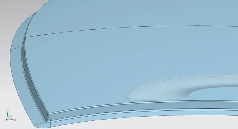
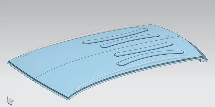
- Flanges & Ditch Area-: The flanges & Ditch area are designed taking in consideration to the various mountings on each side as well as the visibility criteria.
- Front_Roof_Rail-: The Front Roof Rail is designed in consideration to viewing angle and headroom space and other mountings such as rubber backings, windshield etc.
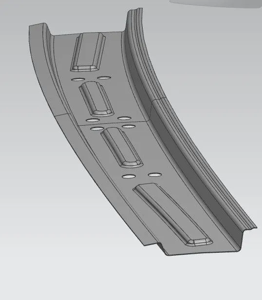
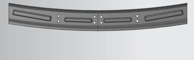
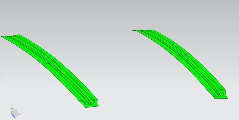
- Bow Rails Roof-: Bow roof Rail are the inner roof rail that provide strength and support to the roof. These are designed and placed taking in consideration to heat distortion & snow load analysis.
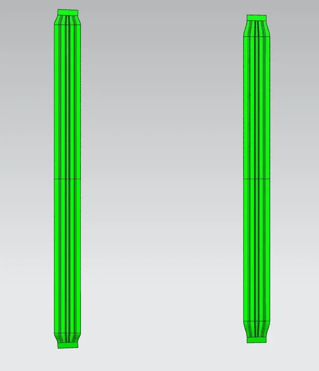
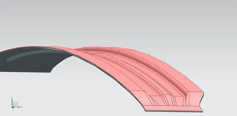
- Centre Rail Roof-:
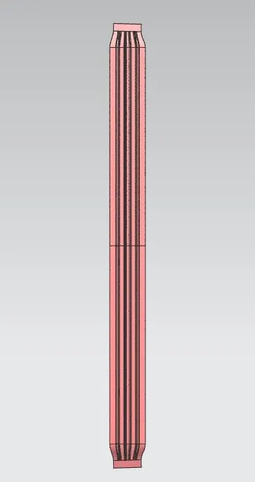
- Rear Rail Roof-:
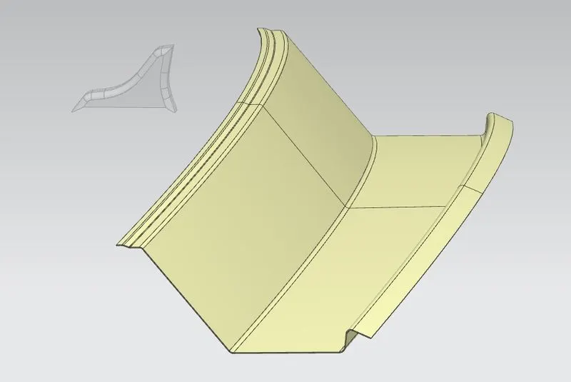
Assembly Components View-:
6. Heat Distortion Analysis / Bow Roof Prediction Formulae-:
W = [1.73 x 10^(-3) x L] + [1.85 x 10^(-8) x (R^2)/t] + [ 1.10x10^(-3) x l] - 2.68
Where,
L = Roof Length in X-Direction[mm](Roof dimension in 0-Y)
R = Roof curvature
R = 2(Rx*Ry)/(Rx+Ry)
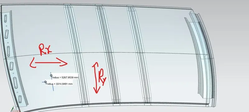
Rx = X curvature
Ry = Y curvature
t = Roof plate thickness [mm]
l = Bow Roof Span [mm]
Case Study-:
Procedure/steps taken-:
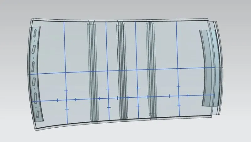
- Drawn a straight parallel line at 0-Y axis on the assembly, offset it by 300 mm on one side and again offset the -300 0-Y line at 100 mm on each side. The 100 mm lines are considered as reference lines.
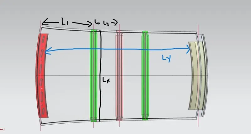
- Now the lines perpendicular to 0-Y axis are drawn at centre of each zone such as it is at equal distance from front roof rail and bow roof rail 1 outer end.
- Similarly, the whole part is divided into 4 sections with these perpendicular lines. Now these lines are again offset at 100 mm on each side as shown in figure below.
- The Intersection points are then marked and projected on the outer panel surface of the roof assembly.
- A 3-D curve is drawn in X axis and Y axis to determine the curvature values of hood at these local areas such as Rx & Ry.
- Then the value of W is calculated for each area and analysed for the judgement criteria, whether our roofs are placed correctly or not.
- Results are attached below in a table for your reference.
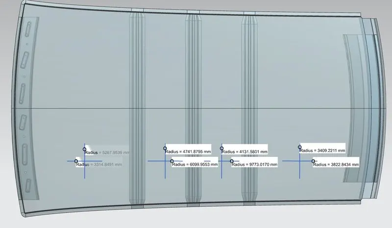
Results for Heat distortion Case study & Bow roof prediction formulae are attached below-:

Conclusion-: Taken into consideration all dimensions we calculated W value for each region and hence results appeared to be satisfied with judgement value OK<2.7. Thus, our bow roofs are placed correctly.
7. Snow Load Prediction Formulae-:
Qr = [Iy x t2] / [α x s x [(Rx + Ry)/2]2 x 10-8]
Note: The Qr value given over here is correct. There was a typo error in the formula given in the video.
Where,
α = My x Lx2 x 10-12 , My = Y(Ly-Y)
t = Roof plate thickness [mm]
Ly = Distance between the front and rear roof Rails on the Vehicle along with 0Y[mm]
Length of Roof panel with the center point between Roof rail Front /Rear as the front and rear reference point.
Lx = Distance between the Left and Right end of the roof on the Roof BOW [mm]
The width of the roof panel is exposed on the surface.
Y = Distance front Front Roof Rail to Roof BOW[mm]
s = Distance for which Roof BOW bears divided load [mm]
s = L1/2 + L2/2
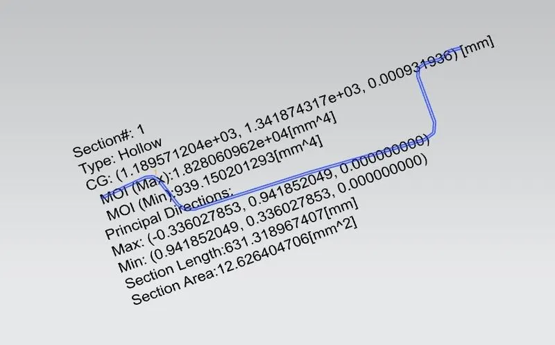
Iy = Geometrical moment of inertia of Roof BOW (Y cross-section )[mm4]
Rx = Lateral direction curvature radius of roof panel Y cross-section on Roof BOW [mm]
Roof panel curvature Radius of the Length Lx in Front view
Ry = Longitudinal Direction curvature radius of the Roof panel X cross-section on Roof BOW [mm]
Roof panel X curvature radius of length s in Side view
Judgment condition
Qr ≥ 3.1
250 ≤ s ≤ 380
Case Study-:
Procedures-:
- The perpendicular lines are drawn similarly but with the reference to centre of each rail such that it is equally situated from centre of front roof etc.
- The parallel line at 0-Y axis is drawn and offset at 100 mm on each direction.
- Offset lines are taken into reference.
- The Intersection points are then marked and projected on the outer panel surface of the roof assembly.
- A 3-D curve is drawn in X axis and Y axis to determine the curvature values of hood at these local areas such as Rx & Ry.
- Then the value of Qr is calculated for each area and analysed for the judgement criteria.
- Results are attached below in a table for your reference.
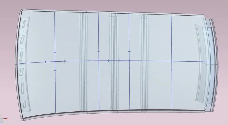
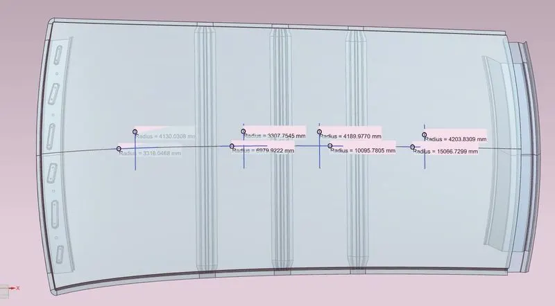
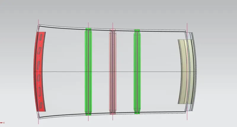
Results for Snow Load prediction formulae are attached below-:

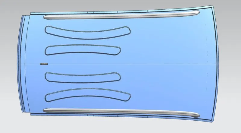
Conclusion-: The above case study is performed taken into all dimensions and values required, as per the results derived the 3rd section appears to fail in Snow load prediction and hence declared as NG in the results. To clear the NG we have 3 measures to taken as follows-:
- Either change the position of bow roofs.
- Change the thickness of bow roofs.
- Provide embosses on to the surface.
Action Taken-: We had provided embosses on to the weaker section surface and hence cleared the NG for the following section. Image attached below.
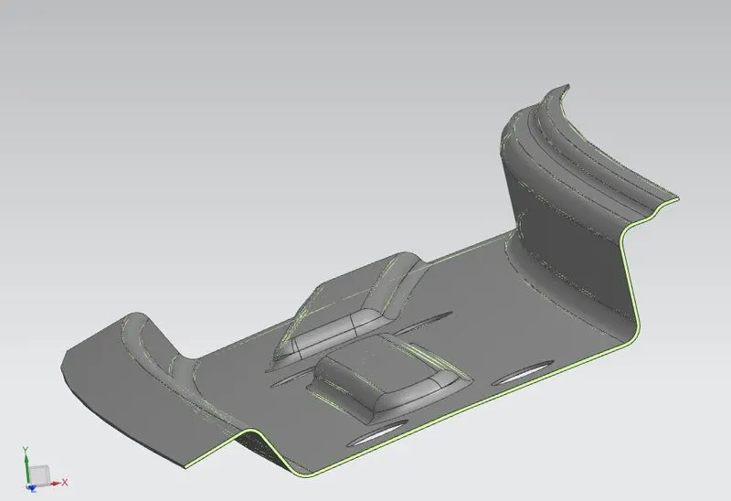
8. Section Modulus Case Study at 0-Y axis-:
a. Front Rail Roof-:
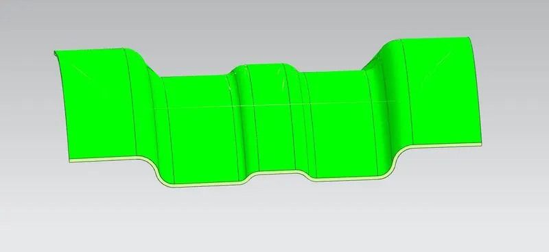
b. Bow Roof Rail_1 -:
c. Centre Rail Roof-:
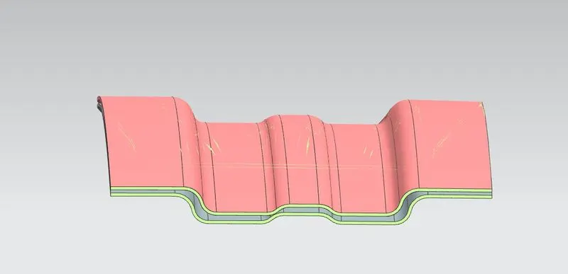
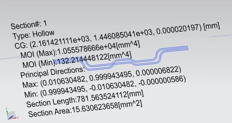
d. Bow Rail Roof 2-:
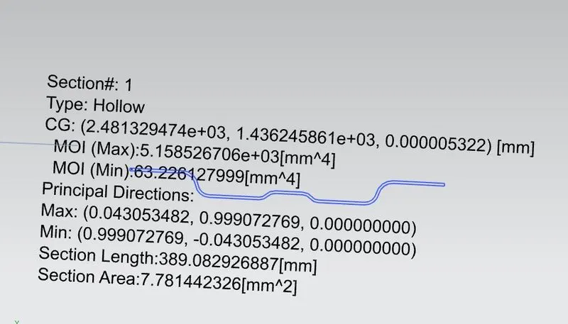
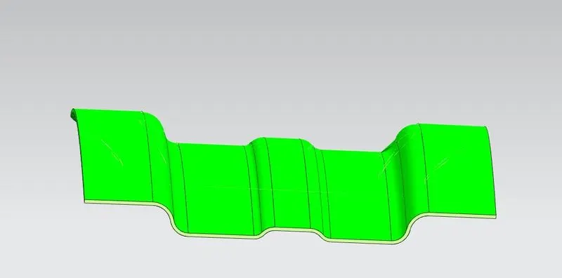
e. Rear Rail Roof-:
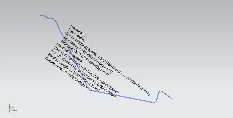
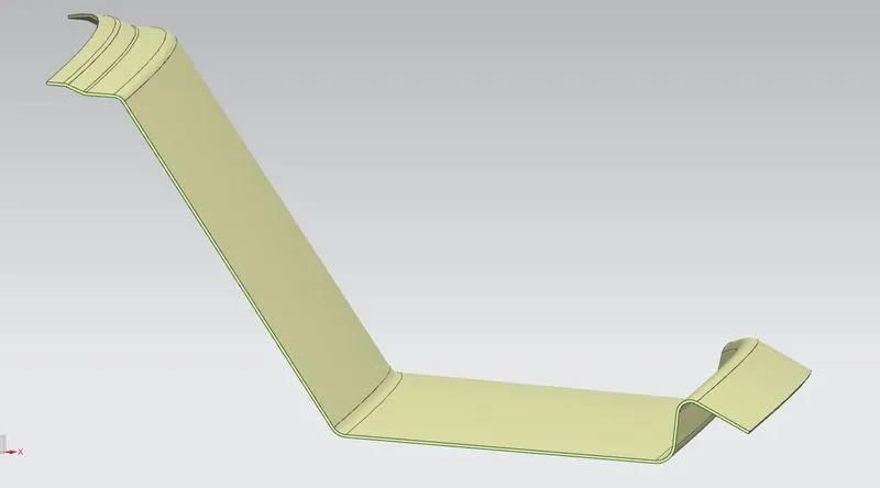
The results for Section Modulus Case study is attached below-:
9. Draft Analysis Case Study -:
Front Rail Roof-:
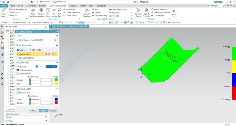
b. Bow Roof Rail 1-:
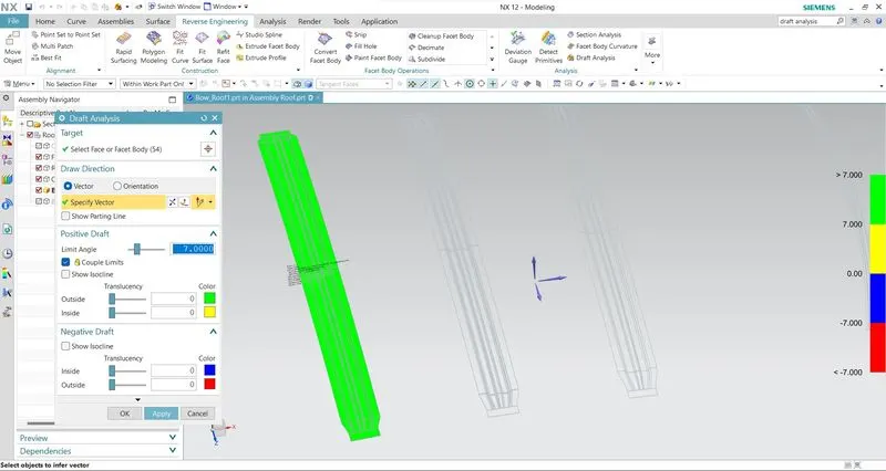
c. Center Roof Rail-:
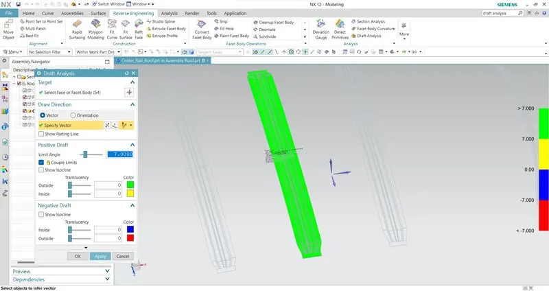
d. Bow Rail Roof 2-:
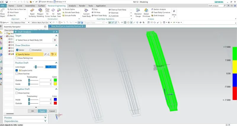
e. Rear Rail Roof
10. Conclusion-:
After completion of this project, we came to know about the significance of the designing of roof and its parameters in real life as per the objective of this project we learnt that-:
- Designing of flanges & reinforcements as per the master sketch and other considerations.
- After performing Heat Distortion case study, we came to know our roof rails are positioned correctly and results for ‘W’ are satisfying.
- After performing Snow load prediction formulae, we came to know about that improvement is required in rear section of the hood as results are not satisfying, we take corrective measures and provided embosses on the particular section of roof.
- After performing Draft analysis for each roof rail, we came to know about that the results are ok.
Final Assembly Views
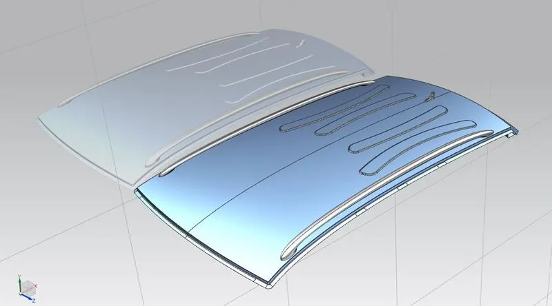
ISOMETRIC VIEW
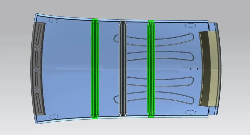
Bottom View
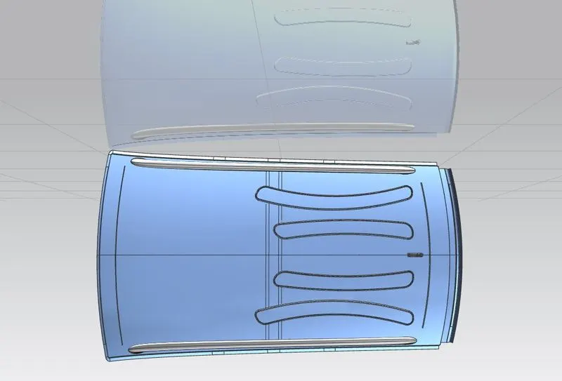
Top View