Roof challenge
DESIGN OF ROOF WITH REINFORCEMENTS AND CALCULATION FOR SNOW LOAD, HEAT DISTORTION.
AIM:
To design a roof from the given class-A styling and also to provide the necessary reinforcements on the required area and predicting the heat distortion and snow load criteria.
PROCEDURE:
Roof
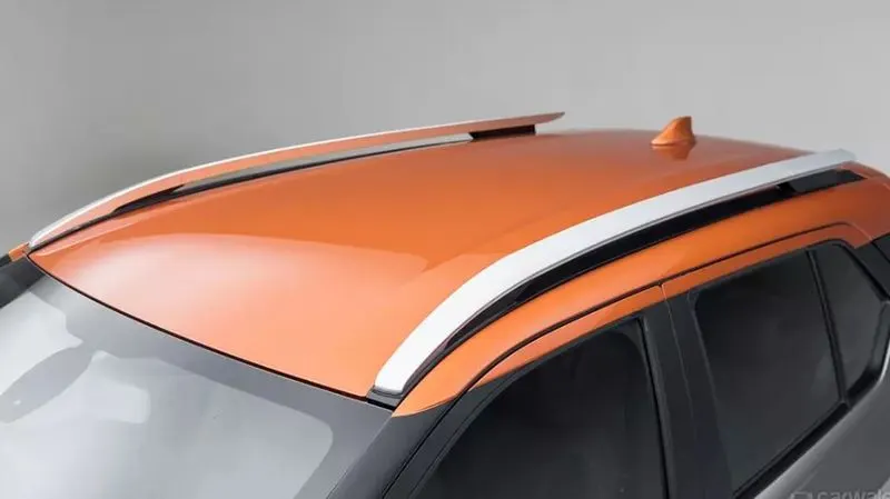
Roof is one of the BIW components, it is the top most part of the vehicle and it gives protection from the outside weather conditions and protection when roll over is happening and also it will absorb the impact load when there is a side crash.
The roof will not contain only outer panel, it will also contain some reinforcement area for good performance in snow load, heat distortion and roll over protection also. The major criteria we are going to see while designing the roof is shown below.
Master sections
As discussed above, the reinforcement panels on the roof will be designed by following the master sections, to ensure the front and rear visibility criteria and manufacturability of the part.
For a roof there are front roof rail, Rear roof rail, centre and other roof bows also. We will decide the design and placement of these bow roofs according to the curvature of the roof also.
The following images shows the master section of the roof bows and roof rails.
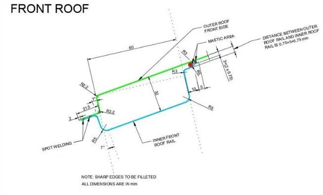
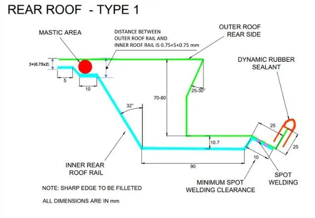
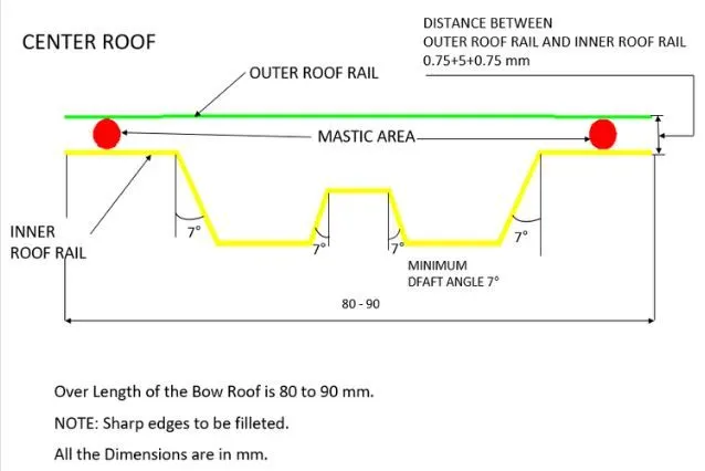
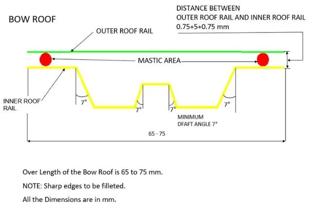
The various types of bow roof’s master section is shown above. The graphical representation of the roof is shown below.
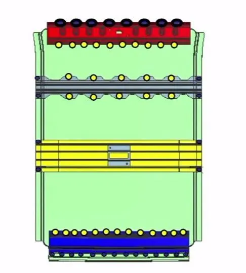
Here in the above image the blue and red region shows the front and rear roof rails, and the yellow area shows the centre roof rails, and grey colour shows the bow roofs.
The given class-A surface for the roof is show below. Outer panel of the roof with the ditch area and reinforcements are also completed from the class-A surface using CATIA V5.
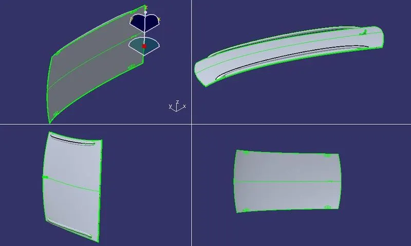
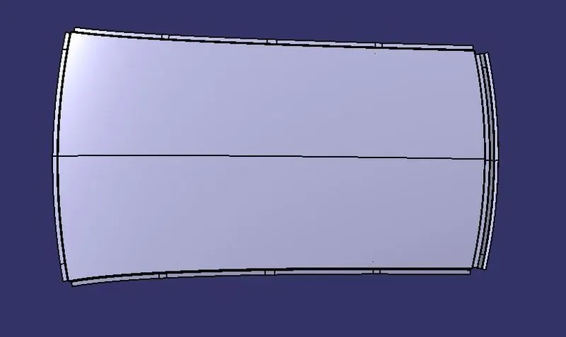
This above image shows the class-A surface and the following images shows the finished parts of the roofs.
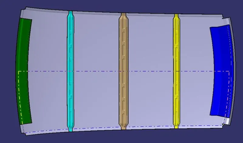
In the above image the grey portion is the roof outer panel,
- Green colour one shows the front roof rail
- Blue colour shows the rear roof rail
- Cyan colour shows the bow roof 1
- Sandy brown shows the centre roof rail
- Yellow colour shows the bow roof 2
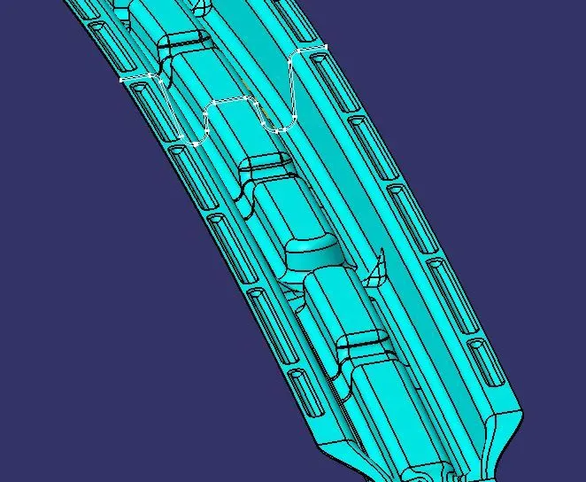
Below images shows the embosses on the roof rails and roof bow areas, and the intersection taken with the planes also represents the given master sections.
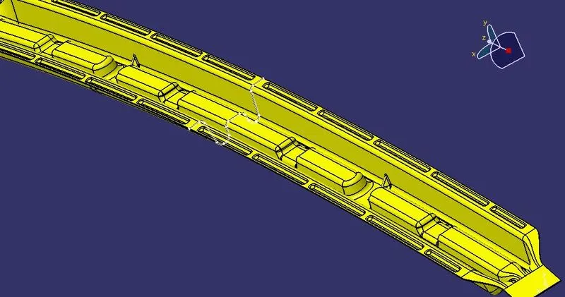
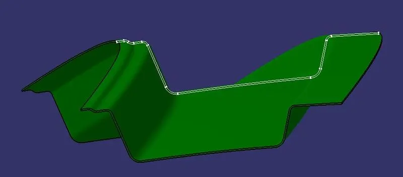
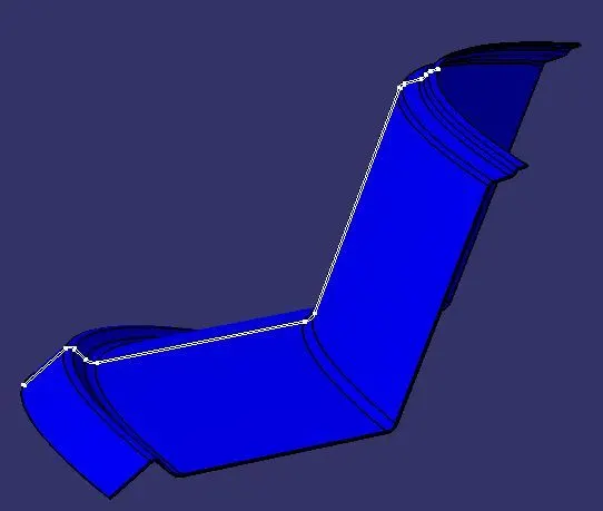
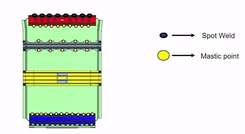
These roof bows and the outer panel of the roofs are attached using the mastic sealants and also by using the spot welding on the ditch area flanges with the other mating parts of the body. It is clearly explained in the below image.
Snow load and Heat distortion calculation
Heat distortion
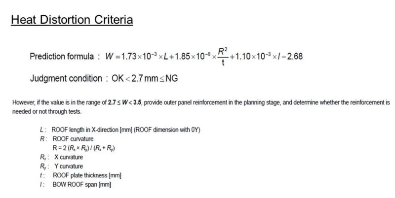
Heat distortion may be defined as the deformation or distortion of the roof when it is exposed to high temperature areas like Africa. So we need to ensure that roof will not fail on those extreme conditions by calculating from the structural part of the roof. The formula for prediction of the heat distortion on the roof is shown below,
And the calculated values for the heat distortion is shown below. And the calculation for the heat distortion is using the sketch is also shown below.
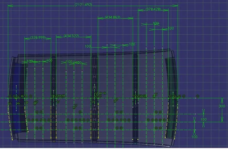
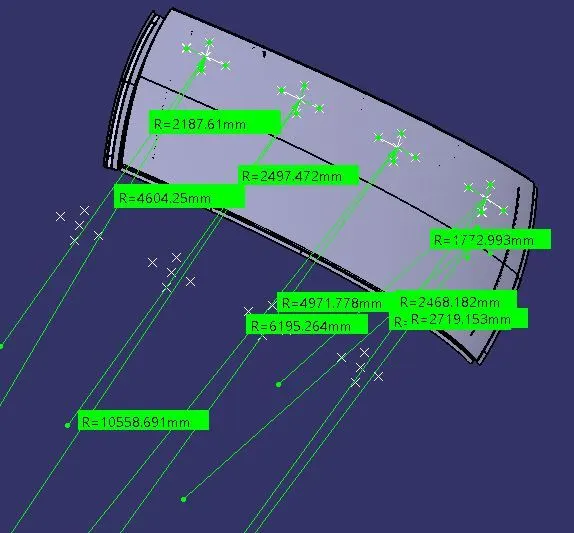
HEAT DISTORTION CALCULATION
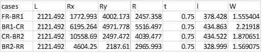
From the above formula the W values should not be higher than the 2.7 so we can say our hood passes all the heat distortion requirement values.
Snow Load
Snow is a dead load applied to the vehicle’s roof when it comes to colder regions, due to the heavy load of snow the hood tends to bend. So our hood should follow the snow load predictions. The formula for the snow load is shown below,
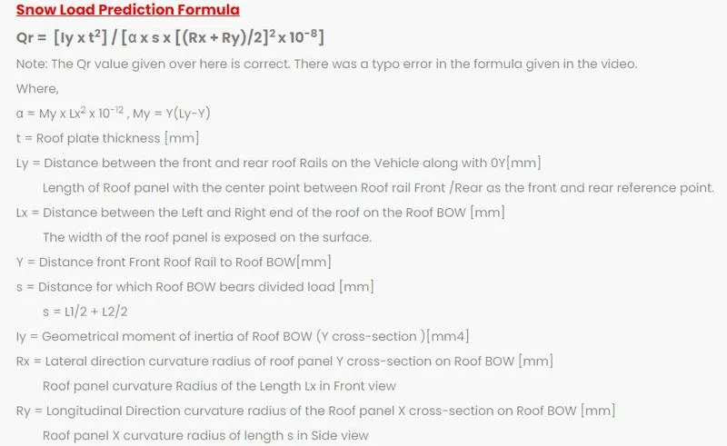

SNOW LOAD CALCULATION
The below table shows the calculation for the snow load.

And the calculations done on the model for the snow load is also shown below,
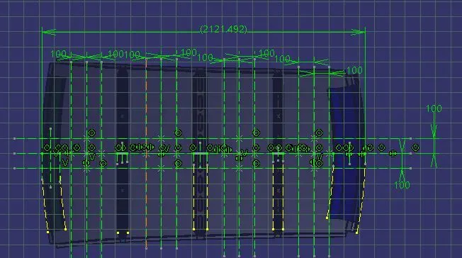
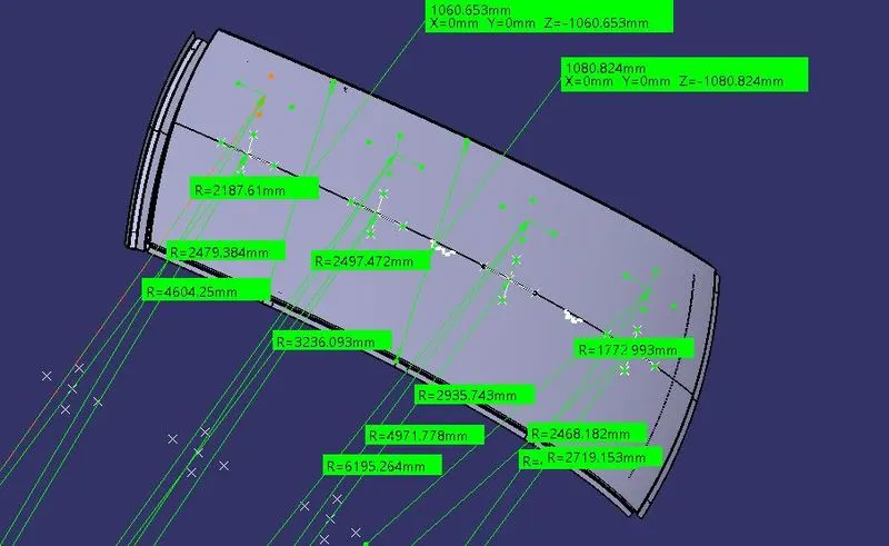
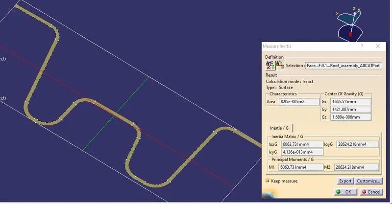
Our roof is also clearing the snow load criteria so it can bear the snow load.
DRAFT ANALYSIS
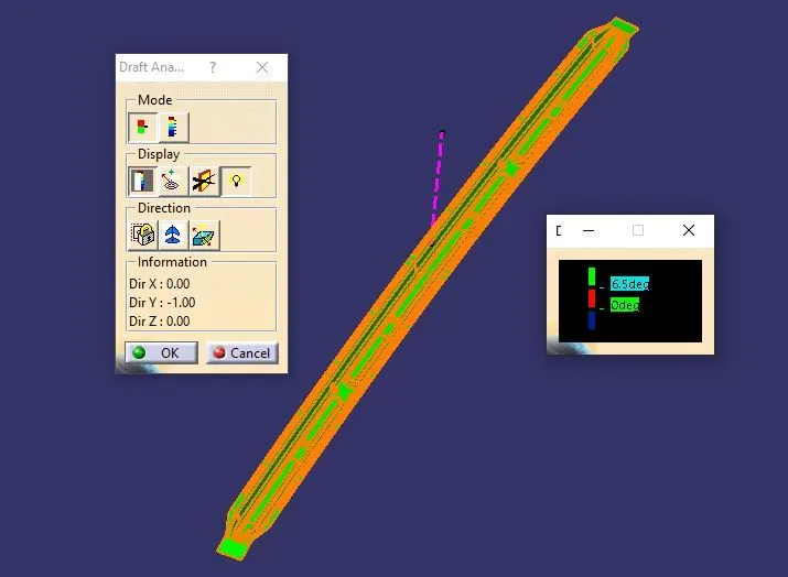
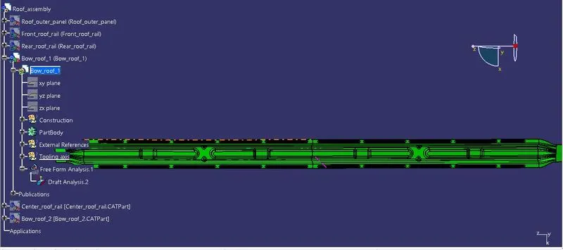
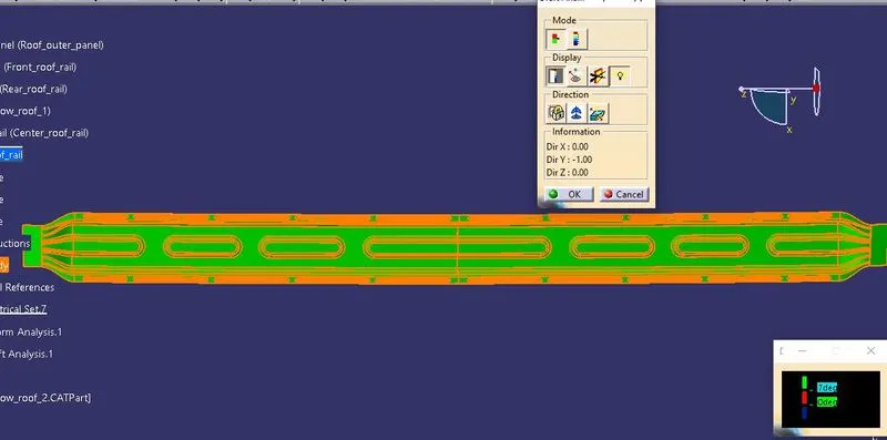
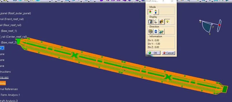
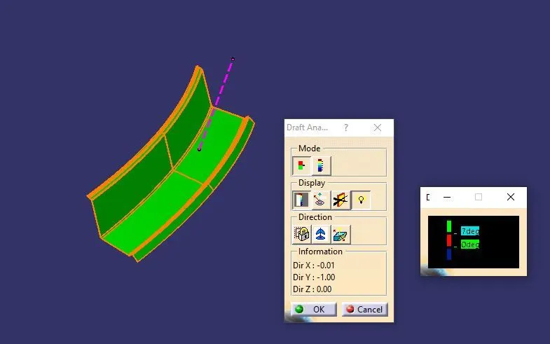
Manufacturability of the part actually depends on the draft angle given on the faces. For sheet metal we need to give 7 degrees of draft and the minimum radius should be 3 plus thickness of the sheet metal part. To ensure the ejection of the part form the dies we have to ensure that proper draft is given or not, to ensure that we can do draft analysis. For the draft analysis we need to specify the tooling axis, for this roof and all of its components we have used Y direction as tooling axis so we can put tooling axis as y direction.
The draft analysis for the each and every parts are shown below.
- Draft analysis for Roof outer panel
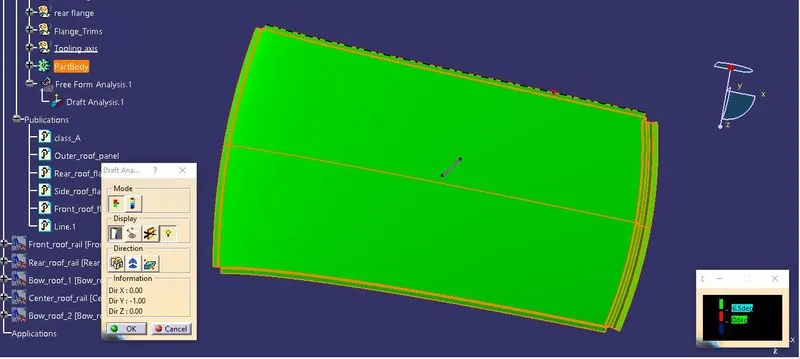
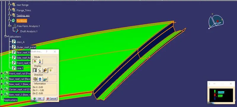
Some of the areas are shown in Blue in colour it shows there is negative draft is given on the faces which are highlighted in blue colour, but it will be done in separate operation so the part can be manufactured.
- Front roof rail
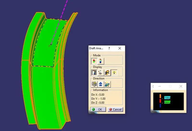
Front roof rail's every faces are clearing on the draft analysis.
- Bow roof 1
- Center roof rail
- Bow roof 2
- Rear roof rail
RESULT
Thus the roof is designed from the class-A styling surface, reinforcements are also designed. Heat distortion calculation and snow load prediction calculation is also done. The manufacturability of the roof is also ensured by giving proper draft and verified by performing draft analysis.