Roof challenge
AIM :
To Design a Car Roof and to do the curvature study to resist heat distortion and snow load condition of the same.
Introduction :
In this project we will study the roofs bow roofs and reinforcemrnt for the roof different design consideration how to develop the design to the component with the master sections and the skin data provided.
DESIGN AND ANALYSIS
Automotive vehicle roof
Safety point of view vehicle roof plays very crucial role specially roll over kind of accidents, in which vehicle tips over onto its side of roof. And vehicle rollover crashes are the causes of many fatalities and several head, neck and spine trauma around the world. Therefore passenger safety is also very important parameter in front of OEM’s. It is not only a marketing strategy but also it is a obligation stipulated by international standards that are now place in several countries, as well as a governmental requirement. For this reason strength is very important criteria for designing vehicle roof.
Roof Headers, Bows & Rails
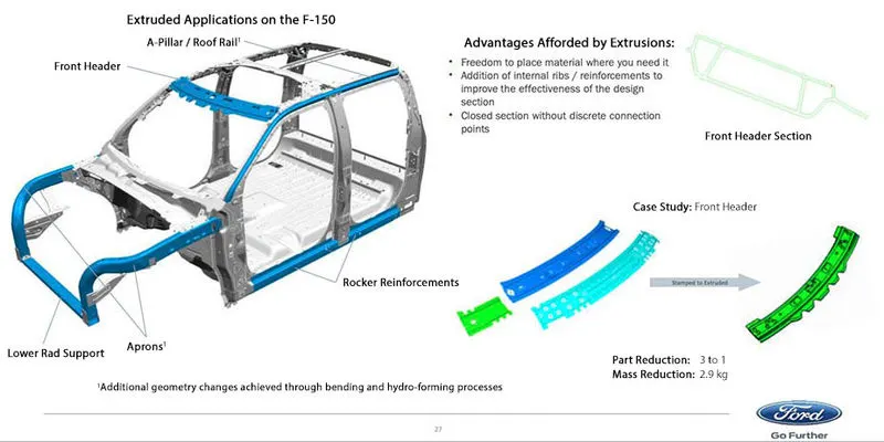
The roof header is the leading component of the safety critical roof structure, supporting the windshield and protecting the passengers in rollover. Roof header materials must be high in tensile strength, low in weight to lower the vehicle center of gravity, high in toughness, and integration-friendly.
A common alloy is 6082 aluminum, a combination that delivers strength, toughness, extrudability – and that converts multiple steel stampings to an efficient, one-piece extrusion on Ford’s flagship vehicle, the F-150.
The weight savings is real, and significant: The Front (Roof) Header on the Ford F-150 delivers 2.9 kg weight savings!
Project Scope
Scope
- Mass saving ideas in manufacturing readiness level 5 and above
- Mass savings estimate in comparison to the baseline
- CAE analysis to match or exceed baseline performance
- Roof Crush
- Bending
- Torsion
- Dent
- Directional material cost estimate and qualitative manufacturing feasibility analysis
Out of Scope:
- Physical Testing
- Absolute Cost
Research Method
The project was done in the following steps:
- Conduct a literature survey of roof lightweighting trends.
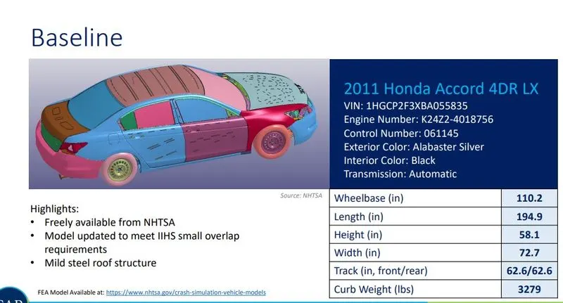
- Define scope of the projectSelect a baseline vehicle.
- Collect roof lightweighting ideas from suppliers using a standard form.
- Analyze and sort the data.
- Select ideas to study via roundtable discussions with the CALM team.
- Hire an independent engineering firm to do the CAE analysis.
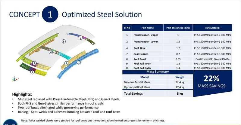
- Work with the CAE firm to combine submitted lightweighting ideas into three concept solutions.
- Analyze the lightweight concepts using FEA analyzes against the baseline performance targets.
- Report the results to the CALM team and automakers.
- Make changes based on the feedback.
- Write and Publish a report.
Future Research
- Develop an all-aluminum roof concept and compare with other concepts developed in this project.
- Test all concepts for vehicle side impact.
- Modify other vehicle components, such as B pillar to match torsional stiffness for concept 2 and concept 3.
- Study materials for panoramic sunroof application.
Load Cases
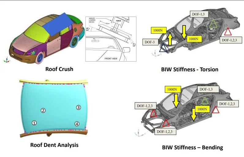
Load Cases
The primary functional requirements for the roof and roof structure are to:
- Provide protection for the occupants from the elements.
- Meet federal roof crush regulations (FMVSS 216).
- Contribute to the structural performance of the body.
- Contribute to maintaining the dimensional accuracy of the body.
Based on the roof structure’s functional requirement, the CALM team selected the following load cases to study for this project:
- Roof Crush.
- Roof Panel Dent.
- Body-in-White (BIW) bending stiffness and frequency.
- BIW torsional stiffness and frequenc.
Roof Crash Test :
- Crushing the roof structure of the vehicle against a rigid plate (platen) until 5 inches of crush is achieved . then, the maximum force sustained by the roof before 5 inches of crush is compared to the vehicle's curb weight to find the strength-to-weight ratio
- The IIHS roof crush rating stipulates that the roof structure must sustain loading of four times the curb weight for a good ratings.
- AS per FMVSS No. 216 testing protocol , roof structure should sustain the load, three times the vehicle curb weight in order to meet the acceptable criteria.
- For this problem we have considered 50kN i.e. 3 times of the vehicle curb weight.
Roof dent analysis:
A Spherical ball of 25.4mm indented on roof with 150N force and the response is recorded in terms of resistance force offered and plastic strain to identify any permanent deformation.
BIW Stiffness – Torsion
Torsion stiffness is the stiffness of the BIW for the twist load conditions, applied on the front shock towers. The BIW is constrained with minimal boundary conditions, at the middle of the front bumper and at the rear spring mount. Force of about 1000N is applied in the opposite direction on the Vertical axis in the shock tower mount. This will induce a static moment on the front shock tower with the rear spring mounts constrained in all translation DOFs.
BIW Stiffness
Bending BIW is constrained at four shock mount locations. A load of 1000N applied at rocker area for bending load cases as shown in next slide.
BIW Stiffness – Bending
Bending Static Stiffness:
The Body-in-White (BIW) is constrained at the four shock mounts positions. A load of 1000N applied at rockers.
Bending Frequency:
The body has resonant frequencies for which a small dynamic force at the resonant frequency can cause large deformations. Although the number of frequencies is infinite, we will calculate lowest frequency of bending.
Torsion Stiffness:
The BIW is constrained with minimal boundary conditions, at the middle of the front bumper and at the rear shock mount. Force of about 1000N is applied in the opposite direction on the Vertical axis in the shock tower mount. This will induce a static moment on the front shock tower with the rear spring mounts constrained in all translation degree of freedoms.
Torsion Frequency: calculate the lowest frequency (mode) of torsion.
Mixed Material Solution – Composite Bows and Panel
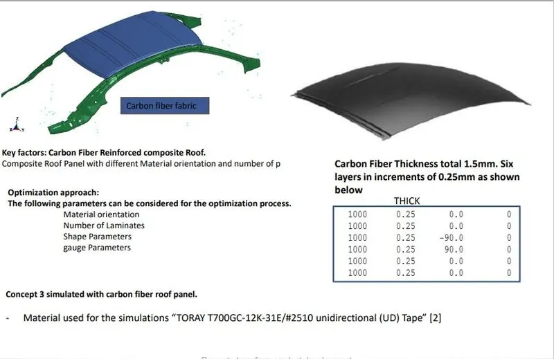
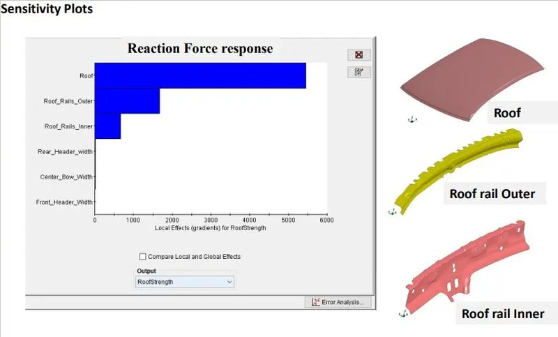
Roof Design
Given surface is A -Class and we have design Roof surface with the help of this A -Class and the help master section which is shown below.
There is two master section for the front end rail roof and the next one is for the rear roof section.
Additional help Images. these images are just to give you a brief idea about the design.
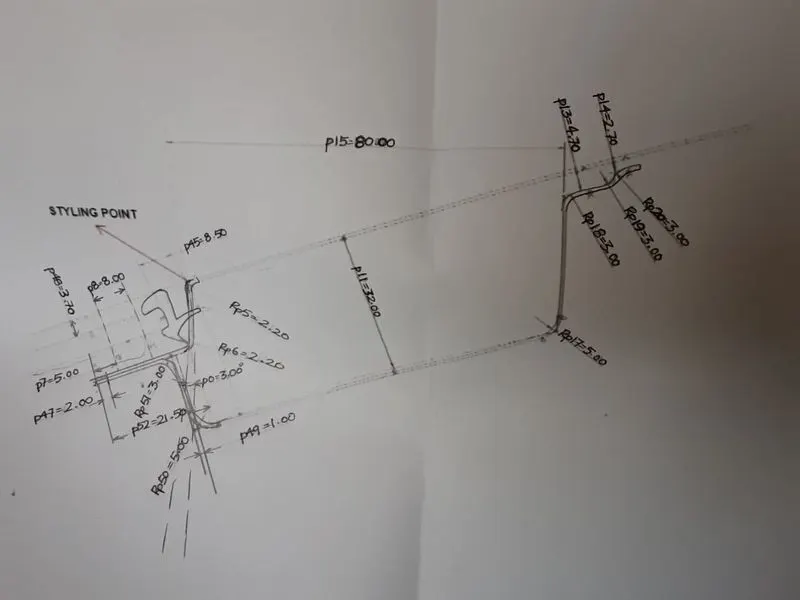
Front roof Rail master section reference image
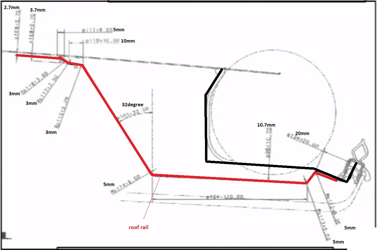
Front roof Rail master section reference image
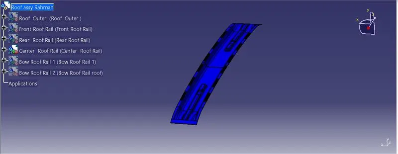
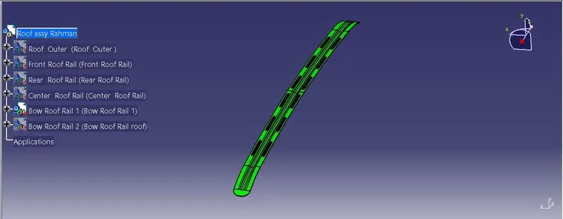
Roof assembly :
- Roof Outer
- Front Roof Rail
- Rear Roof Rail
- Center Roof Rail
- Bow Roof Rail
Roof Outer
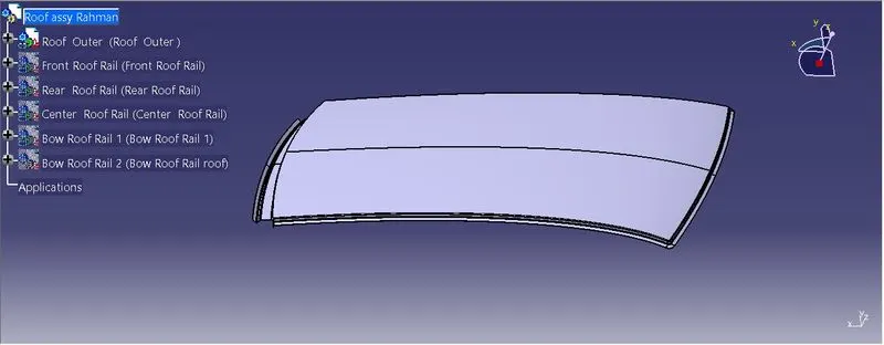
Front Roof Rail
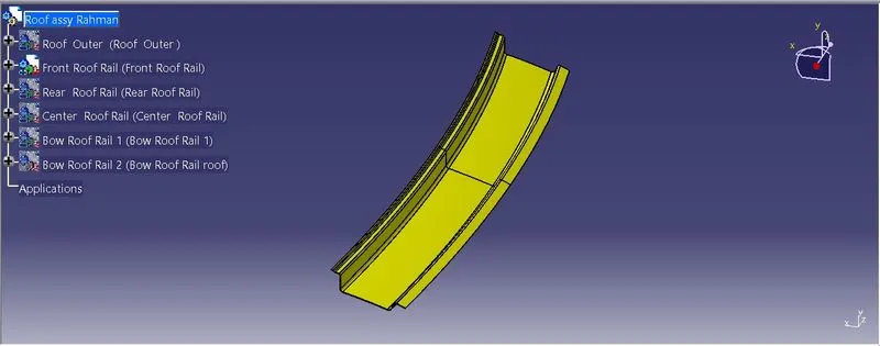
Rear Roof Rail
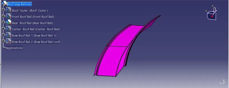
Center Roof Rail
Bow Roof Rail
HEAT DISTORSION:
Bow–roof prediction Formula
W = [1.73 x 10^(-3) x L] + [1.85 x 10^(-8) x (R^2)/t] + [ 1.10x10^(-3) x l] - 2.68
Judgment Condition
OK< 2.7
Where
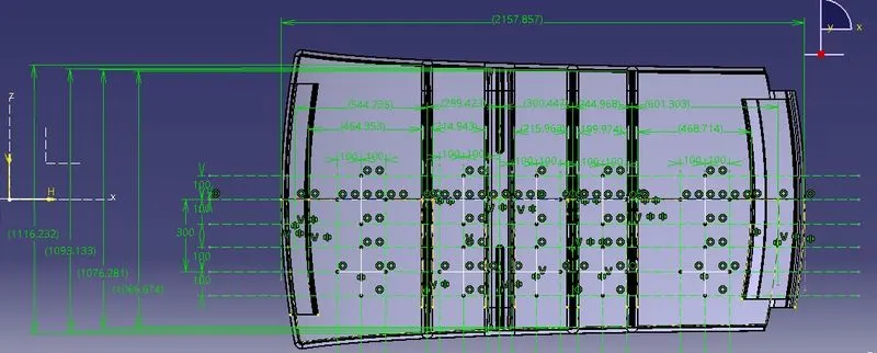
L = Roof Length in X-Direction[mm](Roof dimension in 0-Y)
R = Roof curvature
R = 2(Rx*Ry)/(Rx+Ry)
Rx = X curvature
Ry = Y curvature
t = Roof plate thickness [mm]
l = Bow Roof Span [mm]
Rx = X curvature
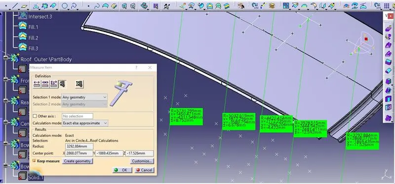
Ry = Y curvature
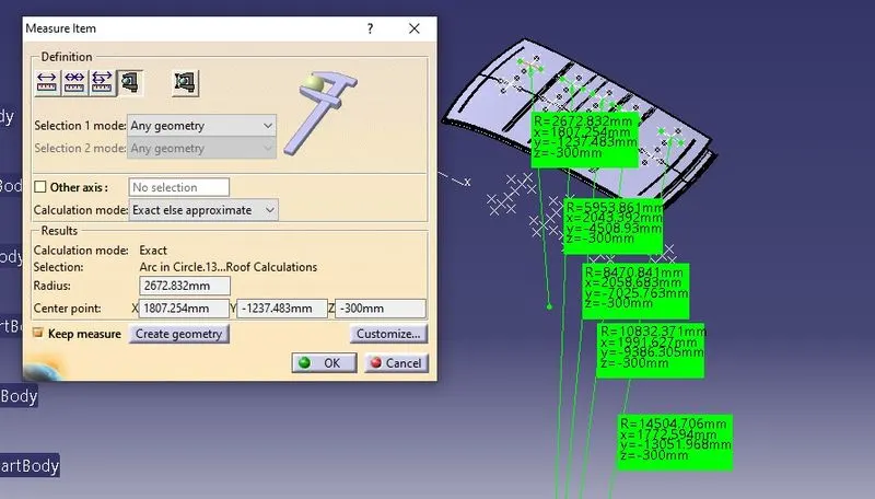
R = 2(Rx*Ry)/(Rx+Ry)
t = Roof plate thickness [0.75 mm]
l = Bow Roof Span [mm]
W = [1.73 x 10^(-3) x L] + [1.85 x 10^(-8) x (R^2)/t] + [ 1.10x10^(-3) x l] - 2.68
Caculations are done and tabulated in the table as given below:
| HEAT DISTORSION |
| Case | L | Rx | Ry | R | t | I | W | Status |
| FRR-BOW 1 | 2157.857 | 5731.299 | 2672.832 | 3645.54 | 0.75 | 464.353 | 1.8917 | OK |
| BOW1-CRR | 2157.857 | 5032.619 | 5953.861 | 5454.616 | 0.75 | 214.943 | 2.023433 | OK |
| CRR-BOW2 | 2157.857 | 4420.414 | 8470.841 | 5809.306 | 0.75 | 215.963 | 2.123104 | OK |
| BOW2-BOW3 | 2157.857 | 3928.515 | 10832.37 | 5765.932 | 0.75 | 199.97 | 2.093127 | OK |
| BOW3-RRR | 2157.857 | 3292.884 | 14504.71 | 5367.279 | 0.75 | 468.714 | 2.279268 | OK |
SNOW LOAD CONDITION :
Snow load Prediction formula
Qr = [Iy x t2] / [α x s x [(Rx + Ry)/2]2 x 10-8]
Note: The Qr value given over here is correct. There was a typo error in the formula given in the video.
Where
α = My x Lx2 x 10-12 , My = Y(Ly-Y)
Judgment condition
Qr ≥ 3.1
250 ≤ s ≤ 380
t = Roof plate thickness [mm]
Ly = Distance between the front and rear roof Rails on the Vehicle along with 0Y[mm]
Length of Roof panel with the center point between Roof rail Front /Rear as the front and rear reference point.
Lx = Distance between the Left and Right end of the roof on the Roof BOW [mm]
The width of the roof panel is exposed on the surface.
Y = Distance front Front Roof Rail to Roof BOW[mm]
s = Distance for which Roof BOW bears divided load [mm]
s = L1/2 + L2/2
Iy = Geometrical moment of inertia of Roof BOW (Y cross-section )[mm4]
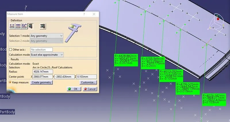
Rx = Lateral direction curvature radius of roof panel Y cross-section on Roof BOW [mm]
Roof panel curvature Radius of the Length Lx in Front view
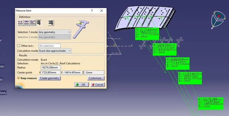
Ry = Longitudinal Direction curvature radius of the Roof panel X cross-section on Roof BOW [mm]
Roof panel X curvature radius of length s in Side view
α = My x Lx2 x 10-12
My = Y(Ly-Y)
s = L1/2 + L2/2
| L1 | L2 |
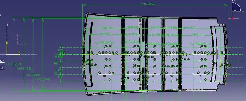
| 544.235 | 299.423 |
| 299.423 | 300.447 |
| 300.447 | 244.988 |
| 244.988 | 601.303 |
| 601.303 | - |
t=0.75
Qr = [Iy x t2] / [α x s x [(Rx + Ry)/2]2 x 10-8]
Iy = Geometrical moment of inertia of Roof BOW (Y cross-section )[mm4]
Rx = Lateral direction curvature radius of roof panel Y cross-section on Roof BOW [mm]
Roof panel curvature Radius of the Length Lx in Front view
Ry = Longitudinal Direction curvature radius of the Roof panel X cross-section on Roof BOW [mm]
Roof panel X curvature radius of length s in Side view
Iy = Geometrical moment of inertia of Roof BOW (Y cross-section )[mm4]
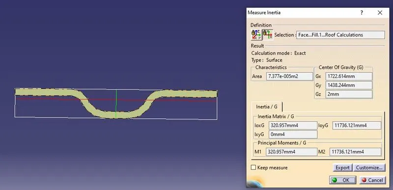
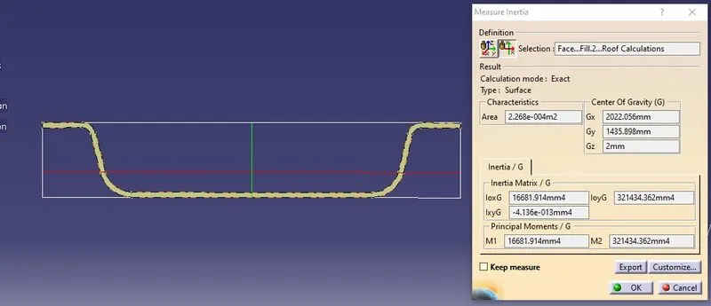
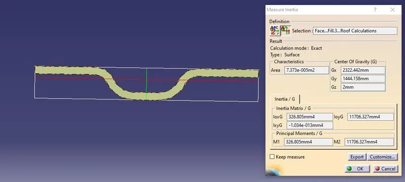
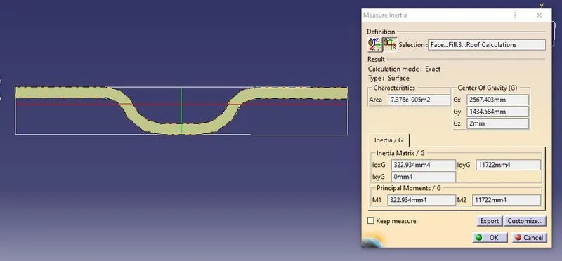
Bow roof movement of inertia is high the Qr value also high, the center roof little too strong.
| SNOW LOAD CONDITION |
| Case | Iy | Rx | Ry | t | Ly | Lx | Y | s | α | My | Qr | Status |
| FRR-BOW 1 | 320.957 | 4428.882 | 2715.446 | 0.75 | 2157.857 | 1116.232 | 544.235 | 272.6677 | 1.094201 | 878189.6 | 4.74215492 | OK |
| BOW1-CRR | 16681.91 | 3755.949 | 5858.995 | 0.75 | 2157.857 | 1093.133 | 299.423 | 150.7149 | 0.664934 | 556457.9 | 405.135519 | OK |
| CRR-BOW2 | 3.27E+02 | 4013.092 | 8588.858 | 0.75 | 2157.857 | 1076.281 | 300.447 | 151.0389 | 0.646438 | 558053.3 | 4.74219993 | OK |
| BOW2-BOW3 | 3.23E+02 | 4296.505 | 11392.84 | 0.75 | 2157.857 | 1066.674 | 244.988 | 124.9484 | 0.533204 | 468630 | 4.43059783 | OK |
| BOW3-RRR | 4026.147 | 16278.39 | 0.75 | 2157.857 | 601.303 | 935960.6 |
Reinforcecement and Design
The Ditch area is the extended portion of the main roof cancealed by other BIW panels. the rail supports of the roof are attached to the Ditch area using spot welds since it is not a styling surface and remains concealed.
Front Roof Rail
it is the support that is joined the windshield glass body side outer and the inner panels its thickness is usually 0.75mm the windshield end flanges are extract offset of the roof surface the bottom mast flanges is decided after taking into consideration the visibility criteria spot weld is applied at the windshield end of the other end is joined with the roof using mastices sealants which also contributes to increase strength.
Rear Roof Rail
it is the support that is joined to the back door and the body side outer and the inner panels .it is usually made from body side outer therfore the thickness of the rail is 0.75mm silmilar to the front roof rail design we have to take into consideration the rear headroom clearance and the rear visibilty criteria while designing the rear roof rail from the backdoor design and also taken into consideration the required clearance spot welds are applied at the back door end the rail and the other end is joined with the roof using masticsealants.
Reinforcecement Center Rail:
lt is the main supporting rod for the roof their purpose is to provide an attachment point for crossbars and other devices designed to secure loads carried on the roof vehicle it absorbs energy at the time of the crash its thickness 0.75mm
Bow Roof Rail
Similar to the other design we have to take into consideration of the consideration of the headroom clearance and the visibility criteria while designing the centre roof rail and bow roof rail here spot weld is not applied for joining these rails of the roofs instead mastic sealants are introduced at bothends since centre roofs are fully positoned under the styling surface of the roof for increasing the strength of the rails embossing is done .to reduce the weight of the material used differnt has been followed withe a thickness 0.75mm
Draft Analysis:
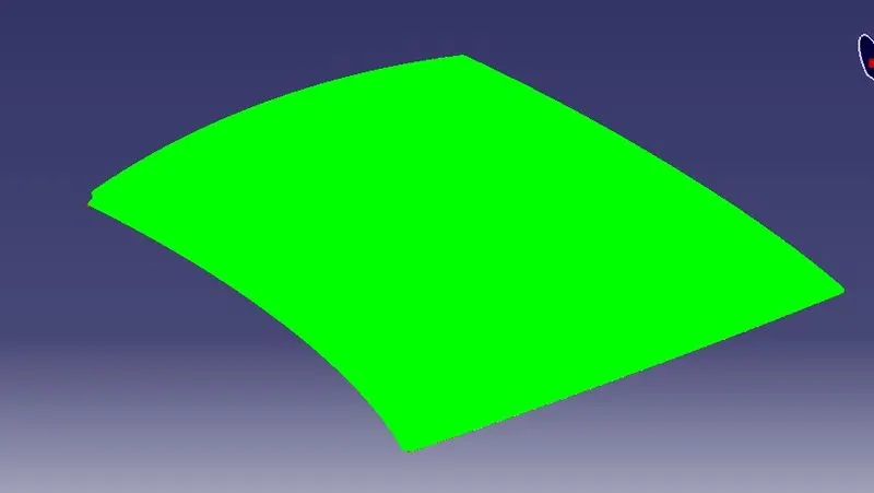
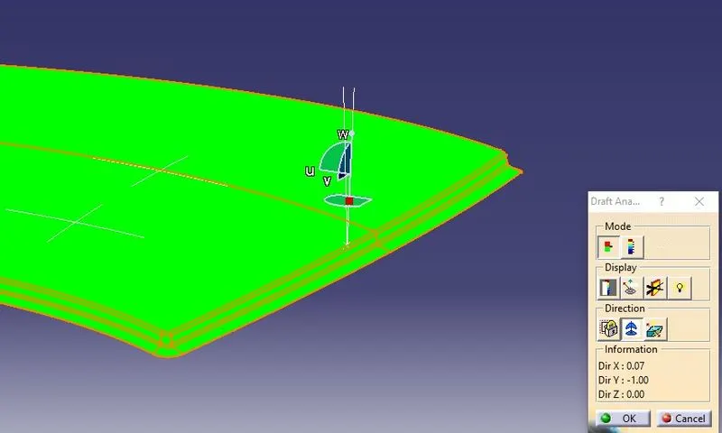
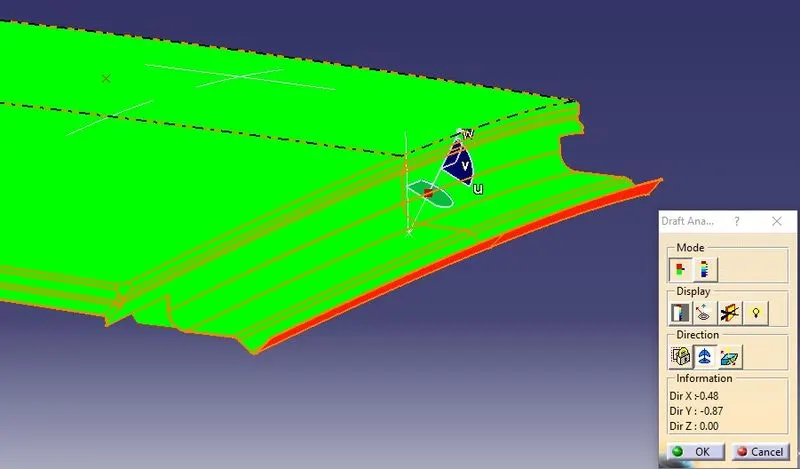
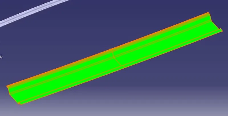
Draft analysis is a method of checking the draft angle on various faces of a part in a particular direction it should be more than 7 degress. draft analyzing command iets you know if your model or design has a draft angle in a given tool direction.
The below figures show the draft analysis for roof front roof rail rear rail bow roofs and reinforcement center.
Draft Analysis Roof Outer
Draft Analysis Front Roof Rail
Draft Analysis Rear Roof Rail
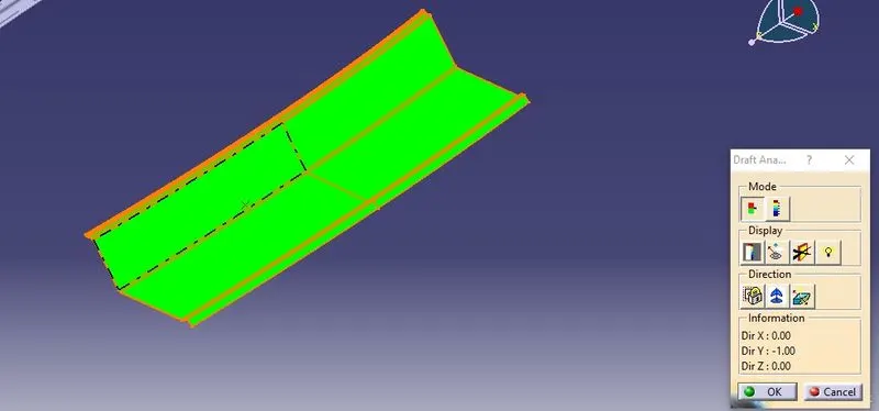
Draft Analysis Center Roof Rail
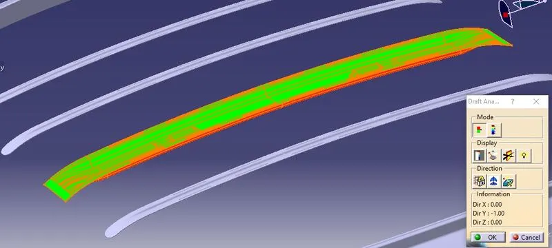
Draft Analysis Bow Roof Rail
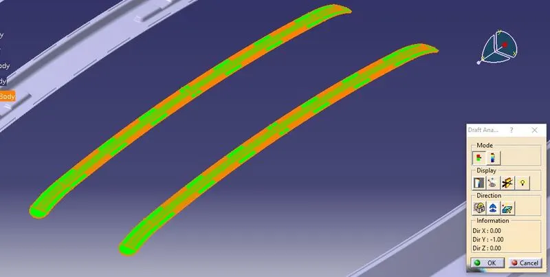
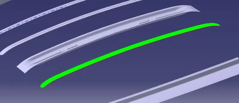
Conclusion :
The roof was created in catia v5 version with all the required parameters and different calculations were done for safety concerns.