Hood design-Week 2
Design Hood outer panel, inner panel and the necessary reinforcements by following the Master section mentioned with the design parameter explained in the videos. Submit an assembly of Hood inner panel, outer panel, latch, hinge and the reinforcements
Aim:
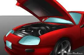
Bonnet is main component of a car at the front portion. It is used to decorate the car and add luxurious look. The shape of the bonnet is made aerodynamic in order to minimize the air effect. Bonnet is generally used to access the parts easily such as radiator, engine and many other parts. In automotive world the weight optimization plays an important role. In this paper material changes is applied to the bonnet for the same design and finally showing the stiffest bonnet and less weight component. For designing the hood 3D model CATIA V5 .
Method
Technical Regulation
A technical regulation is established before it is possible to carry out larger construction project. In appendix A one can find a functional template, taken from an other earlier Volvo project, that shows different topics that can be followed to create a good technical regulation. Below is the development of a technical regulation for a car hood, and the content of this has a large influence on this investigation. Using Apendix A as a template.
Technical Regulation, Car Hood
What is the purpose of the product, what is the task?
Reduce damage of pedestrian considering head impact, associated with low speed crash with pedestrian. Protect the underlying parts and the motor from theft, also to take away the ability to disable the car alarm. Protect parts under the hood from environmental damage, like corrosion and water. Give the car better aerodynamics and a good look with styling.
Function Determining Properties
Weight: lower than the current mass of the hood, which is 10 kg. Temperature: withstand temperatures in the range of -30 to 100◦C. In the case of a head impact the hood shall absorb enough energy so the ”Head Impact Crid eria” or HIC value not become higher than the legal demands in the different zones on the hood. The buckling force in the hood shall be lower than thestrength in the hinges, so that the hood is plastically deforn in a controlled way in high speed crash to avoid hitting and breaking the windscreen. The hood must be stiff enough, that no oscillation occurs while driving in high speed.
Theoretical Background
Hood Section
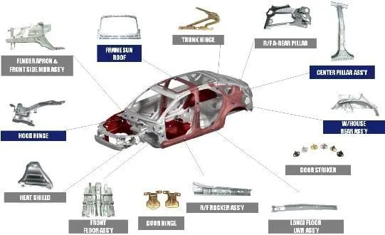
The sub system hood consists of a hood, striker, opening system, latch and in some cases pedestrian safety system. The main functions for the hood are to protect the under-hood system and work for pedestrian safety. The system should allow inspection of the engine and service of the under-hood systems, for example filling fluids. Together with the latch system and opening system, the hood should fulfill the demands in ergonomics concerning opening-closing forces and opening geometry. It should be robust enough to not be damaged by normal daily usage of the car.
Hood Complete
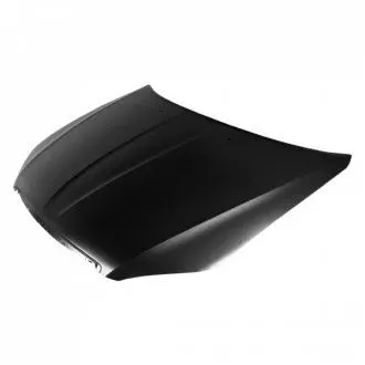
The hood is a design element and is the part of the body that borders to the front fenders, front lights, bumper and the plenum cover. The complete hood consists of an inner and an outer plate joined together by hemming around the edges of the hood. Rubber based glue is used in the flange joint as glue between outer and inner hood and on points as well in the inner plate pattern as anti-flutter. Today a certain pattern is used in order to fulfill the requirements for pedestrian safety and total stiffness in the hood. Front reinforcement lock striker reinforcement and hinge reinforcements (steel) are clinched to the inner plate. Spot welding is used in part assembly of front reinforcement. The hood weight is about 10 kg. This is considered too high and a po tential for improvement by weight reduction is to be worked towards. The greatest potential areas for weight reduction are material changes and redesign of the inner hood.
Hood Geometry
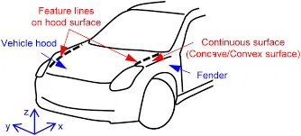
The hood geometry has a huge influence on the pedestrian safety of the hood. The different shapes like bends and roundings makes the hood stiffer and harder in some places, a head impact in these areas can lead to large damage. Then the more flat area of the hood are more soft and more gentle for a pedestrian head impact. The inner hood has a complex design and geometry, this is necessary because it helps to distribute the stresses throughout the hood. It also con sists of different holes for manufacturing and assembly. Figure 6 shows an example of the complex geometry of the inner hood. It is important to optimize the hood to the new material in order to utilize all thopportunities to integrate and optimize shape to a new process, Today the hood i optimized to the sheet metal stamping and sheet metal composition. Usually only two bump stops are used, these are to be placed as far forward in the front and aspossible.In the larger cars, two additionally bump stops is necessary in the front due to the size and weight of the hood. The hood is mounted in the body factory (A-shop). It is then passes through the paint shop (B-shop).
Pedestrian Protection
Background
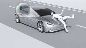
According to accident statistics in Europe about 41.000 deaths occur in traffic. 6.100 (15%) of these are pedestrians and another 3.900 (10%) are cyclists. For pedestrians the most frequent injuries occur in the head, upper and lower limbs. 62% of all fatalities are caused by head injuries. These head injuries happens when the pedestrians head contacts the vehicle or the ground[10]. To reduce the death of pedestrian and injuries in the traffic, measures from the automotive industry as well as environmental changes are required. The European Enhanced Vehicle Safety Committee has developed test pro.
cedures to estimate the level of pedestrian protection for the front parts of the vehicles. Based on the EEVC WG 17 report, legal requirements have been derived. The European directive consists of head impact, upper leg impact and lower leg impact To test how good the cars is at pedestrian protection, the car industries performs different tests on the cars that simulate an real life accident with head impact, upper leg impact and lower leg impact. In the hoods perspective, the head impact protection is the most common and is in the highest priority
Head Impact Test
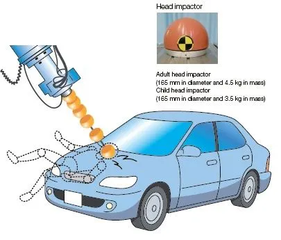
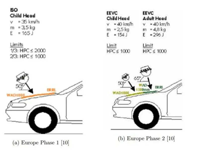
The risk of head injuries is in free flying head impacts and that is investigated by a free flying head form impcator, impacting against the vehicle hood. The head impact test are tested for both adults and children and it isexecuted by, the head testing impactor is fired towards the hood and simulatea real life head impact The impactor are equipped with a three dimensional accelerometer. From the measured results from the accelerations the HIC (Head impact Criterion) valueis calculated with Equation1 with a maximum time limit of 15 milliseconds .

For Europe the limit for HIC is separated into two differentarea
- Hood top zone AHIC ≤ 1000
- Hood top zone BHIC ≤ 1700
Upper Leg Test
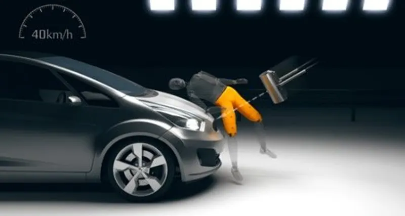
Upper leg impact test
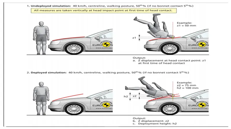
To estimate the potential risk of pelvis and upper leg injuries in the event of a vehicle striking an adult, a series of impact tests is carried out at 40 km/h using an adult upper leg form impactor as Impact sites are then investigated and the protection offered is rated as good, adequate, marginal, weak or poor.
IMPACT-ABSORPTION BONNET AND BUMPERS
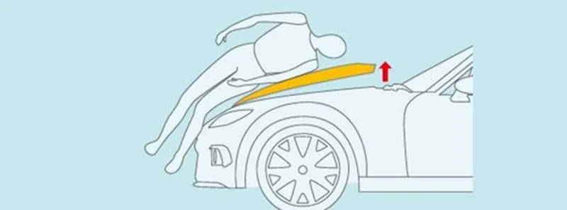
Mazda uses various methods to reduce injury to pedestrians in the event of a collision.The Impact Absorption Bonnet mitigates the impact to a pedestrian's head in a pedestrian accident.Active Bonnet is designed to mitigate shock to the head in the event the vehicle collides with a pedestrian. Designed to activate with a defined speed range, the system causes the rear end of the bonnet to pop up when an impact exceeding a certain threshold is detected, creating a shock-absorbing space between the bonnet and the engine.Energy absorption materials are used in the front part of the vehicle which hits pedestrians' knee to mitigate the severity of pedestrian's knee injuries. Also, stiffening reinforcement is placed at the bottom of the bumper to better prevent pedestrian's leg from going under the vehicle. In anticipation of an accident, the shape of bonnet is carefully designed to reduce the damage to the pedestrians' knees, which are an important part of the body for walking.
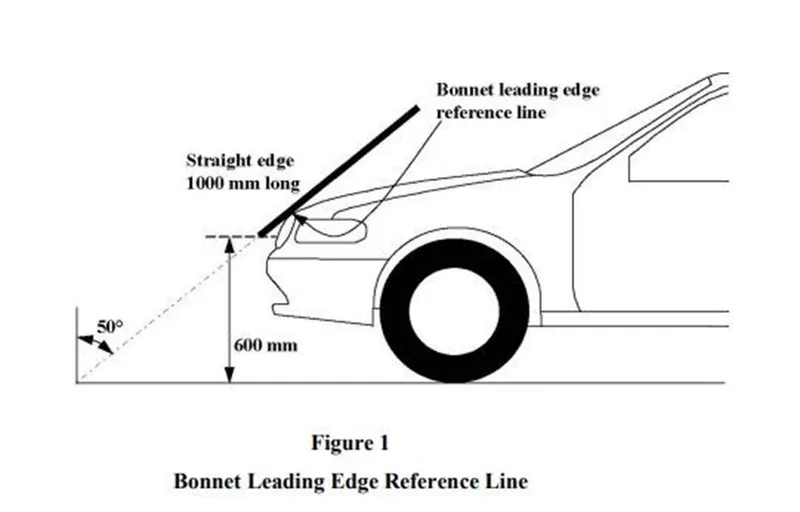
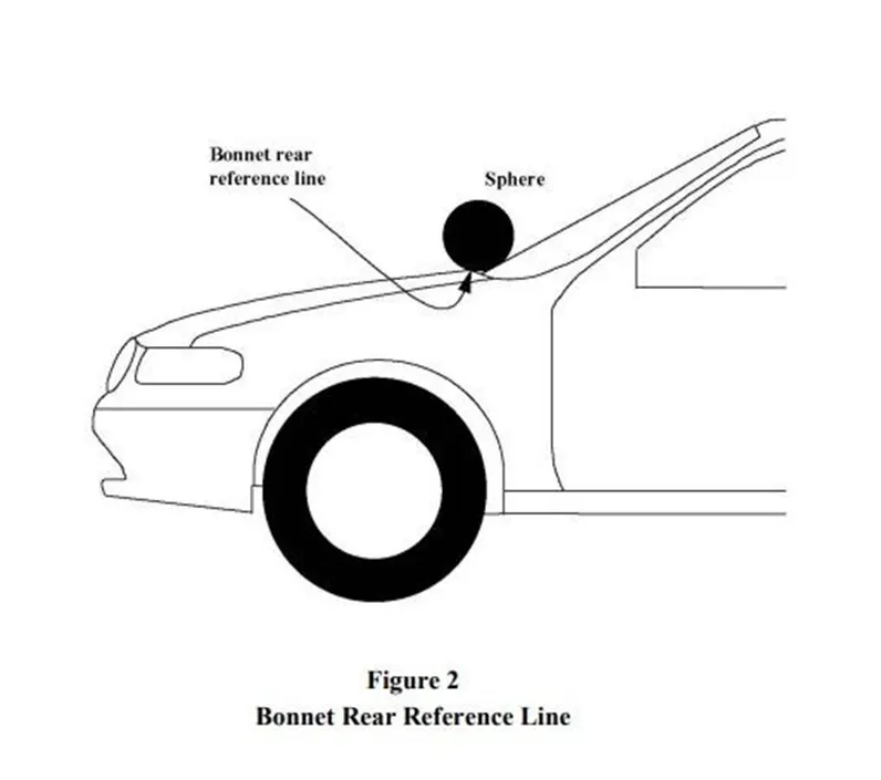
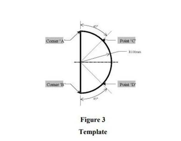
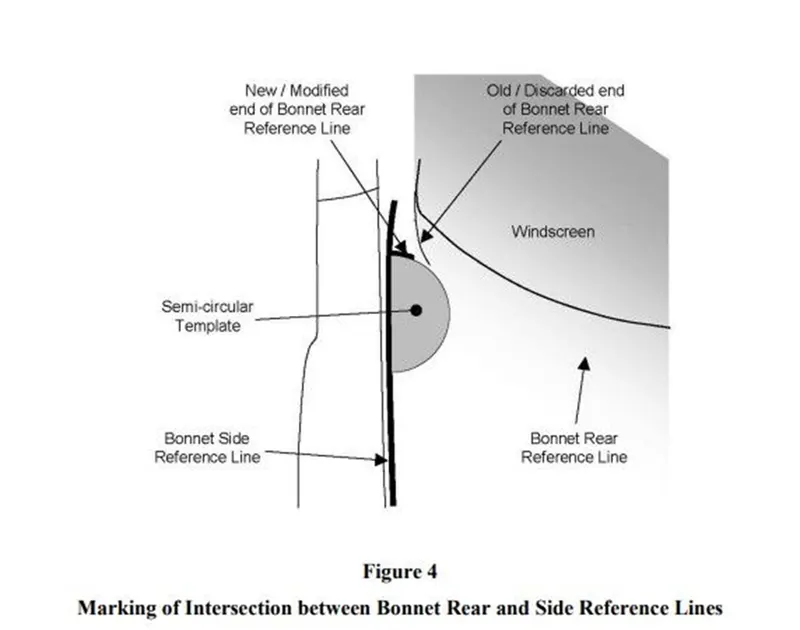
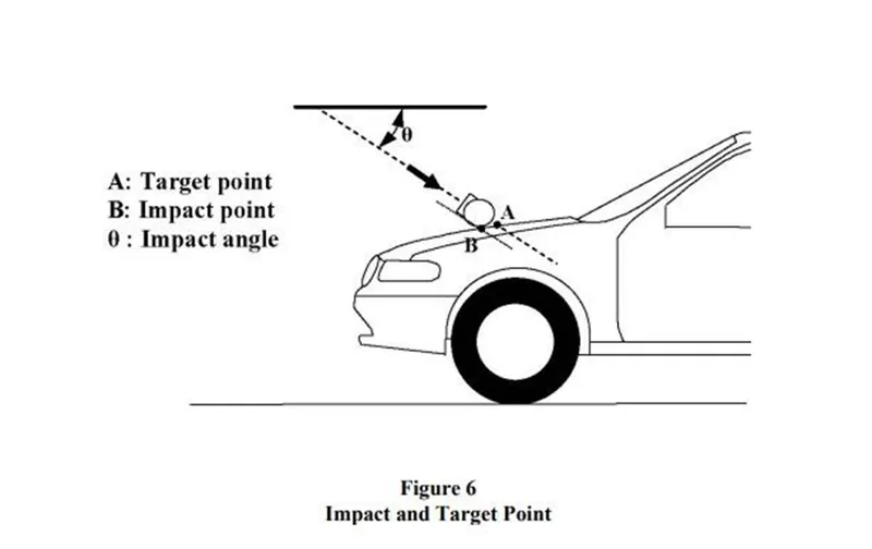
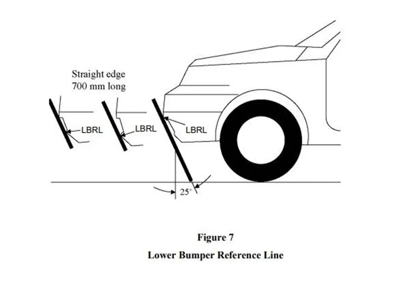
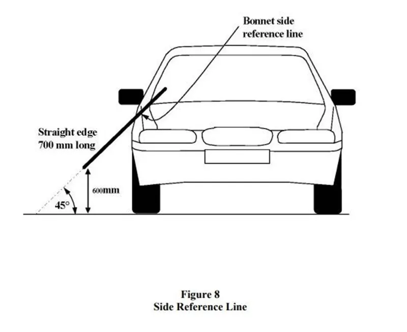
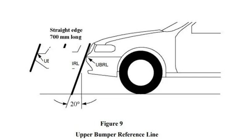
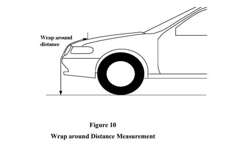
"Bonnet rear reference line" means the geometric trace of the most rearward points of contact between a 165 mm diameter sphere and the front structure of the vehicle when the sphere is traversed across the front structure of the vehicle while maintaining contact with the windscreen . The wiper blades & arms are removed during this process. Where the bonnet rear reference line and the side reference line do not intersect, the bonnet rear reference line should be extended and/or modified using a semi-circular template, of radius 100 mm. The template should be made of a thin flexible sheet material that easily bends to a single curvature in any direction. The template should, preferably, resist double or complex curvature where this could result in wrinkling. The recommended material is a foam backed thin plastic sheet to allow the template to "grip" the surface of the vehicle. The template should be markedup with four points"A" through"D", as shown in Figure 3, while the template is on a flat surface. The template should be placed on the vehicle with Corners "A" and "B" coincident with the side reference line. Ensuring these two corners remain coincident with the side reference line, the template should be slid progressively rearwards until the arc of the template makes first contact with the bonnet rear reference line. Throughout the process, the template should be curved to follow, as closely as possible, the outer contour of the vehicle’s bonnet top, without wrinkling or folding of the template. If the contact between the template and bonnet rear reference line is tangential and the point of tangency lies outside the arc scribed by points "C" and "D", then the bonnet rear reference line is extended and/or modified to follow the circumferential arc of the template to meet the bonnet side reference line, as shown in Figure 4.If the template cannot make simultaneous contact with the bonnet side reference line at points "A" and "B" and tangentially with the bonnet rear reference line, or the point at which the bonnet rear reference line and template touch lies within the arc scribed by points "C" and "D",then additional templates should be used where the radii are increased progressively in increments of 20 mm, until all the above criteriaare met.
Data to be used:
Hood Thickness Information
- Outer Panel Thickness = 0.75mm
- Inner Panel Thickness = 0.75mm
- Reinforcement Thickness = 1.5mm
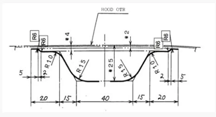
Master sketch:
Hood Outer Pannel:
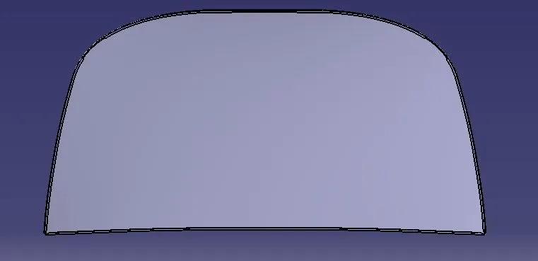
Outer pannel is nothing but a outer skin of inner panel .otherwise called as a cover of inner panel. it is the part, which gives luxurious look to the hood or bonnet outer pannel and pannel cannot join by any welding process like spot welding or rivet which spoil the outer look of a car the outer pannel is generally extracted model from the prototype design.
Hood Inner panel :
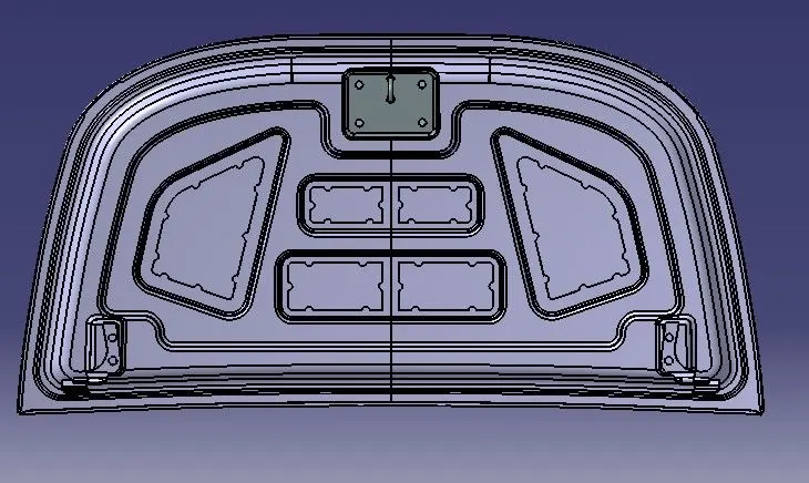
The inner panel is the part that gives strength and rigidity to the outer panel the master section represents the initial emboss shape and size it is where the hood balancer and hinges are attached.
Hinge :
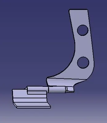
A hinge is a component that fixes the hood to the engine compartment of the car one part of the hinge is connected to the engine compartment and the other part is connected to the hood inner panel the hinger allows the hood to rotate around a fixed axis for opening and closing movement.
Embossing :
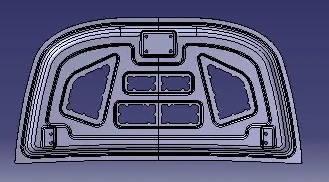
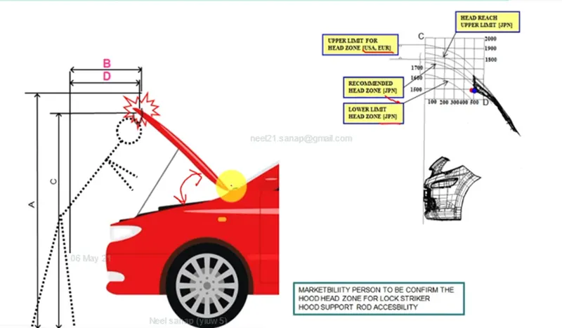
the main aim of embossing process is to the panel by removing some parts of the hood sheet it is a stampingprocess where sunken or projenction are made the panel which provide stiffness also the embossing is created in such a way that the frontal impact deviates the force away from the passengers during collision hood opening angle is considered as important factor and the standard varies brtween the countries based onthe aveage height of the person
Sheetmetal Operations in car hood manufacturing Process:
Deep Drawing :
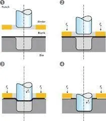
it is a sheet metal forming process in which a sheet metal blonk is radially drawn into a from ing die by the mechanical action of a punch .the process is considerred deep drawing when the depth of the drawn exceeds its diameter.
Hemming :
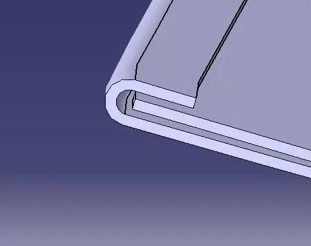
Hemming is a sheet metal forming process in which sheets are joined by bending it to 180°. Automotive body panels and automotive parts such as deck-lids, trunk-lids, doors, hoods and tailgates are formed by hemming process. In this process, usually a sheet is bent with the help of inner sheet in three different stages.
Hemming is a forming operation in which the edges of the sheet are folded or folded over another part in order to achieve a tight fit. Normally hemming operations are used to connect parts together, to improve the appearance of a part and to reinforce part edges.
In car part production, hemming is used in assembly as a secondary operation after deep drawing, trimming and flanging operations to join two sheet metal parts (outer and inner) together. Typical parts for this type of assembly are hoods, doors, trunk lids and fenders.
The accuracy of the hemming operation is very important since it affects the appearance of the surface and surface quality. Material deformations, which occur during the hemming process, can lead to dimensional variations and other defects in parts. Typical hemming defects are splits or wrinkles in the flange, material overlaps in the corner areas or material roll-in. This is why it is important to use simulation tools in order to, on the one hand, better understand the hemming process and, on the other hand, significantly reduce the number of “trial and error” loops during tryout und production.
There are various types of hemming operations:
- Conventional die hemming
- Roll hemming
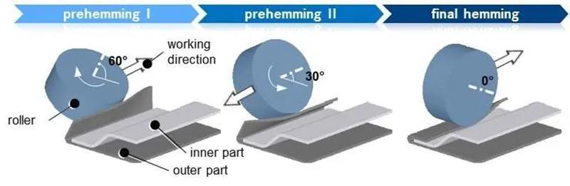
Conventional die hemming:
Conventional die hemming is suitable for mass production. In die hemming, the flange is folded over the entire length with a hemming tool. Normally the actual hemming is a result of a forming operation in which the flange is formed with a hemming tool after the drawing and trimming operations have been completed. The formed flange is then hemmed in several process steps. These steps include, for example, the pre-hemming and final hemming depending on the respective opening angle of the flange. Production plants for conventional die hemming are very expensive, but the cycle times are very low.
Roll hemming:
Roll hemming is carried out incrementally with a hemming roller. An industrial robot guides the hemming roller and forms the flange. Roll hemming operation can also be divided into several pre-hemming and final hemming process steps. Roll hemming is very flexible to use and tool costs are significantly lower as compared to those of conventional die hemming. However, the cycle times are much higher since the hemming is realized using a hemming roller which follows a defined path.
Mastic sealants:
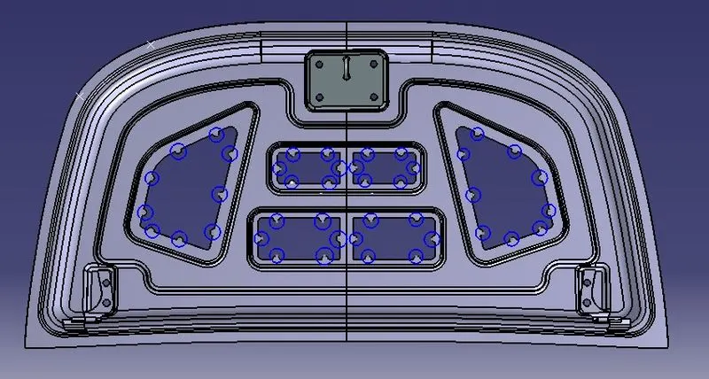
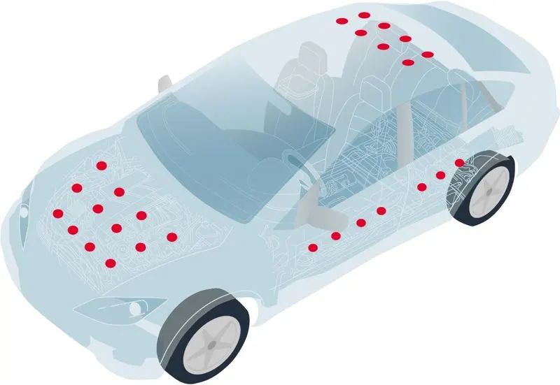
A selection of high quality vehicle-specific mastic joint sealants & adhesives from professional vehicle assembly sealant and adhesive manufacturers such as Sika, Geocel and Otto Chemie for a wide variety of commercial and industrial sealing & bonding applications around all types of vehicles. There's specialist Sikaflex vehicle assemble sealants and vehicle adhesives for windscreen assembly, maintenance and repairs, vehicle sealant & adhesives suited to vibration dampening etc. and polyurethane vehicle mastic sealants for waterproofing and bonding which adhere perfectly to a variety of substrates and are suitable for a wide range of timber, metal and glass.
Hood striker:
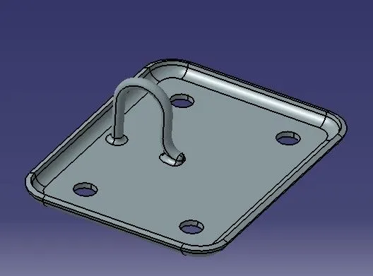
it boits to the underside of the hood at the front .it engages the hood latch when closed for the term hood striker may also exist other definitions and meaning and definition indicated above are indicative not be used for medical and legal or special purposes.
Support Rod:
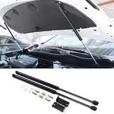
it is a device that supports the hood in open position it is also called as hood balancer rod .
Important features used in designing :
Trin Body : it is used to trim one or more bodies using a face or plane .you can also specify the bodies to retain and the badies to discard.
Offset surface :it allows you to offset one or more existing surfaces.
Offset in Face : this command will allow you to offset particular edges or curves on selected faces.
Trim sheet : it is used to trim off a portion of a sheet body using curves faces edges or planes.
Through curves: it will allow you to create a body through multile sections, where it shape changes to pass through each section .
Law Extension: This command extendss a curve a edge to create a sheet body at desired angle length by changing the rules under angle law and length law .
Trim and Extend:It helps you to trim and extend intersecting surfaces and make corner at their intersection.
face blend :it creates fillets between faces.
Edge Blend :it creates fillets on edges .
Extend sheet : it will allow you to extend an existing surface to required distance.
Emboss :Emboss command creates an embossing by modifying a body with face created by projecting a curve section along a direction you can modify the emboss using options like endcap location and draft angle.
Projected Curve:It is used to project an existing curve on a selected plane or surface by selecting a direction for projection .
Mirror Geometry : As name suggests it allows you to mirror geometries about selected plane or surface.
Thicken: it is used to couvert a suface to solid body by providing thickness.
Extrude:it helps you to create a feature from a sketch you are also able to create thin feature using a sketch or curve under this command.
Desigh Methodology:
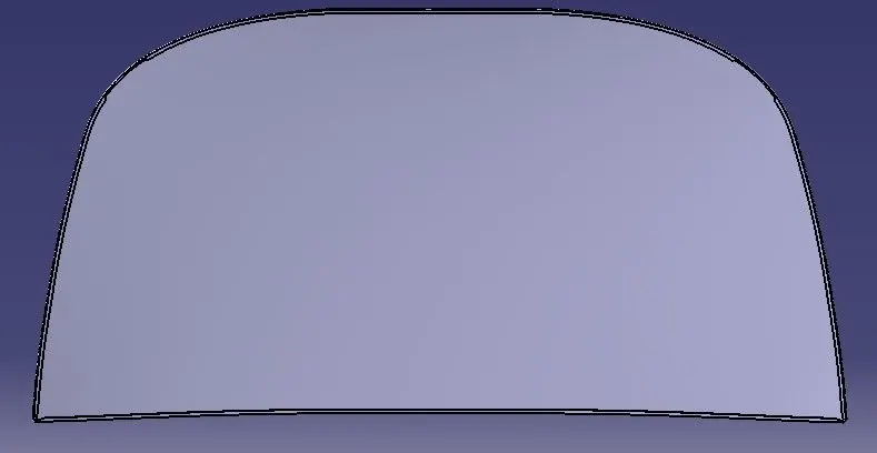
- The procedure followed for designing the hood and its compnents is as follows
- First the inner panel is designed from the given master section usion the various commands and features
- We create the embossing using the offset surface from the original master section
- Silmlarly we create the cuts on the emboss by sketching and using trim surface option
- Then the outer panel is designed from the master section here we are supposed to provide the hemming to outer panel
- The parameters of hemming are taken as per given values.
- Now on the inner panel the embossing for hinge and striker are produced by considering their respective dimensions and assembly positions
- First the emboss for hinge is created and then by fixing the hinge into its position we draw an axis passing through both both side side hinge axes to form a common axis and then we position
- The striker such that it will move along circumference o a circle whose is at midpoint of the common axis thus position of striker is decided and we can create emboss for the same .
- Using the hinge emboss we created we can create our hinge reinforcements by creating new parts in the assembly itself.
Data to be used:
Hood Thickness Information
- Outer Panel Thickness = 0.75mm
- Inner Panel Thickness = 0.75mm
- Reinforcement Thickness = 1.5mm
Conclusion: I designed the car hood along with its components and assembled the same using catia v5 under given parameters.