Roof challenge
PROJECT REPORT
AUTOMOTIVE
BIW DESIGN
AUTOMOTIVE ROOF DESIGN
Automotive BIW Design using NXCAD | SWAROOP T
INTRODUCTION
An automobile roof is the portion of an automobile that sits above the passenger compartment, protecting the vehicle occupants from sun, wind, rain, and other external elements. Other than protecting the passengers from sun, rain etc. roof have a major role protecting the passengers from rollover accidents. Roof crush is the failure and displacement of an automobile roof into the passenger compartment during a rollover accident. Vehicle rollover crashes are complex events which result in a relatively higher fatality rate than any other crash scenarios. In the USA in 2007, the Fatal Analysis Reporting System indicated that there were approximately 10,000 people killed as occupants involved in light-vehicle rollover crashes. This accounted for over a third of occupant fatalities in crashes for that year.1 In the UK, statistics from the UK’s Co-operative Crash Injury Study indicated that, between December 2002 and September 2008, around 21% of contained occupant fatalities involved some elements of vehicle rollover crash.
Under the roof outer panel that is seen from the outside, there are many other structures under the roof which contribute to its strength and stability. The number of such reinforcement structures/supports differs with respect to the size of the vehicle. They are primarily installed on flatter areas of the roof to enhance the strength.
They are classified as front Roof Rail, rear Roof Rail, centre roof rail and bow roofs, which are spot welded to roof flanges & ditch area and improve NVH value by increasing strength of roof using mastic sealants.
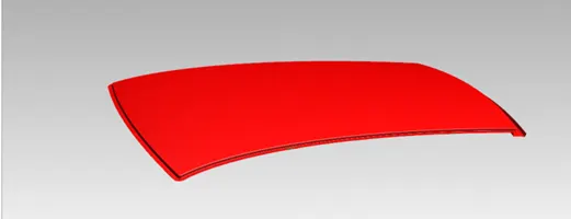
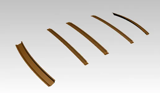
Rendered image of Roof outer panel and rails designed using Nx cad
Objective
For the given Roof styling surface from styling department, develop the roof with essential flanges and reinforcements, Provide appropriate dimensions and check for draft analysis, and find section Inertia on the 0-Y section. Start with the creation of a roof ditch area the tool opening angle is only 3 degrees. Do a curvature study on the roof and perform calculations to determine the position of the bow-roof prediction Formula.
Factors influencing Roof design:
- Visibility criteria
- Head clearance
- Curvature study
- Heat distortion and snow load criteria
- Draft
- Safety parameters
Components to be designed:
- Roof outer panel with necessary flanges and ditch area
- Front roof rail
- Rear roof rail
- Centre roof rail
- Bow roofs
1. Roof outer panel with necessary flanges and ditch area
It is the extended portion of the main roof concealed by other BIW panels. The various roof rail supports mentioned above are attached to the ditch area using spot welds as it is not a styling surface viewed from outside. On other regions, rails are attached to roof using mastic sealants which also improve the NVH factors of the car. Headroom Clearance, visibility criteria, clearance for wind shield and back door are some of the factors to be considered while designing the ditch Area. Here it is given a thickness of 0.75 mm. 4mm gap is maintained between rail upper surfaces and roof panel inner surface for mastic sealant application. Minimum 7 degree angle is maintained while creating flanges considering manufacturability of the part so that the tool can be pulled away from the object easily, without deformation or damage. Embosses were provided for improving the strength of the roof.
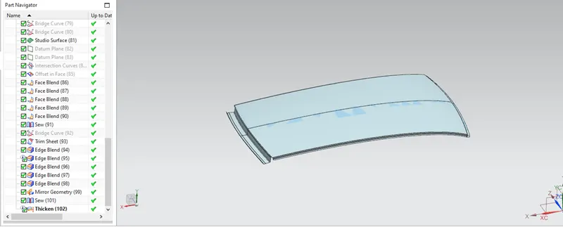
Roof outer panel with necessary flanges, and area
1. Front Roof Rail
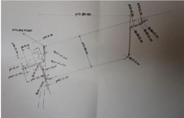
Master section
It is the support which is joined with the Wind Shield Glass, Body Side Outer and the inner panels. The thickness of the part is 0.75mm. A draft angle of 7 degrees is provided keeping in mind the deep drawing operation. Necessary embosses and beads were provided for better strength of the part. The Wind Shield end flange is the exact offset of the roof surface. The bottommost flange is designed after taking into consideration the visibility criteria and the Headroom Clearance of the passengers. Spot Welds are applied at Wind
Shield end of the rail and the other end is joined with the roof using Mastic Sealants which also contributes to increased strength and NVH factors.
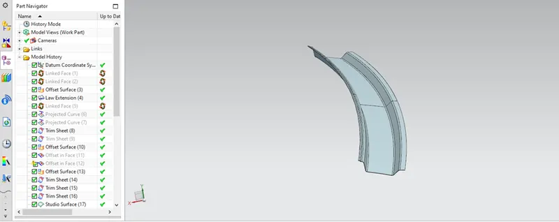
Front Roof Rail
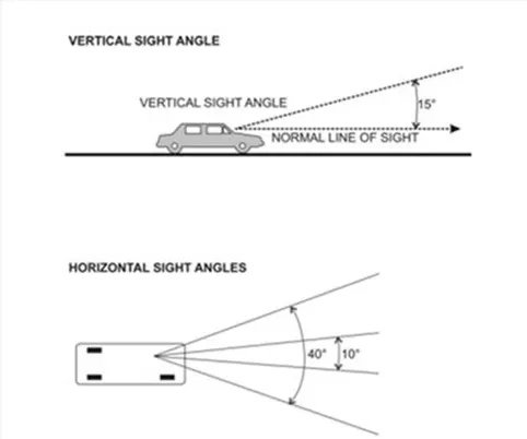
Front visibility criteria: 21.50mmprojection for 15°vertical viewing angle as per master section
3. Rear Roof Rail
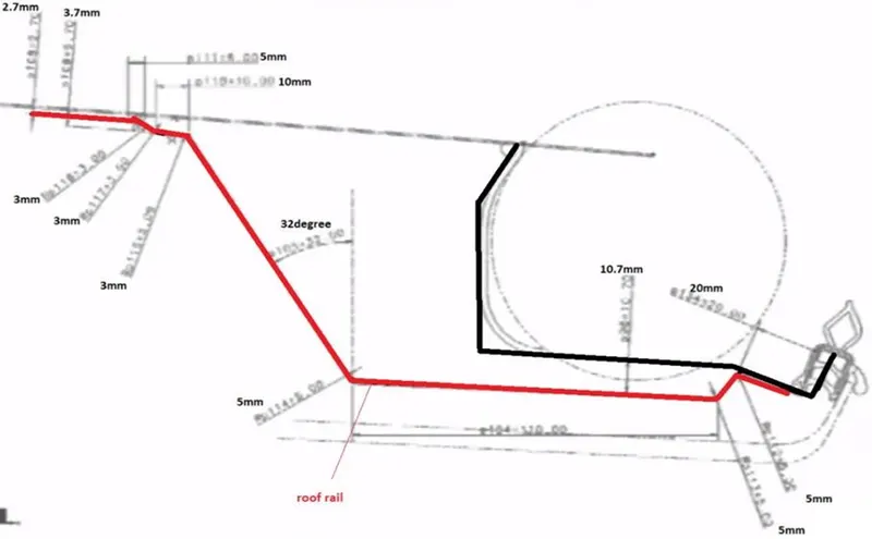
Master section
It is the support which is joined to the back door and the body side outer and the inner panels. The thickness of the part is 0.75mm. Necessary embosses and beads were provided for better strength of the part. Similar to the Front Roof Rail design, we have to take into consideration the rear headroom clearance and the rear visibility criteria while designing the Rear Roof Rail. Inputs from the backdoor design are also taken to accommodate the required clearance. Spot Welds are applied at the Back door end of the rail and the other end is joined with the roof using Mastic Sealants.
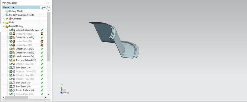
Rear Roof Rail
4. Centre roof rail with bow
Here a bow roof is placed inside along with centre roof rail for better strength and support for roof. For increasing the strength of the rails, embossing is done and beads are provided. Both bow roof and centre roof rail are spot welded to each other. Unlike the Front and Rear Roof Rails, Spot Welds are not applied for joining these rails to the roof. Instead Mastic sealants are introduced at both the ends since Centre Roof Rail and Bow Roofs are fully positioned under the Styling surface of the Roof. 5mm gap is maintained between rail upper surface and roof panel inner surface for mastic sealant application. Thicknesses of the parts are 1.50 for improving the MOI (Moment of Inertia) characteristics. Centre roof rail will be usually connected with the B pillar support structure which improves the support for roof in case roll-over. Centre roof rails will have overall 80mm – 100mm width.
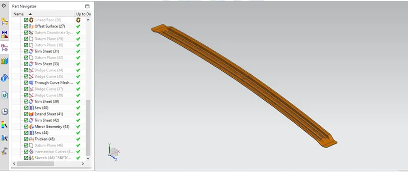
Centre roof rail with bow
5. Bow roofs
The Bow roofs are used to improve the torsional stiffness and load-bearing capacity of the roof structure. They are mostly positioned at comparatively flat regions of the roof. The number of bow roofs provided will depend upon the overall dimensions of the roof. Longer and flatter the roof is more number of bow roofs are used. They are attached to the roof outer panel using mastic sealants. Each mastic point will have up to 80 mm circular effective area. 4mm gap is maintained between upper surface of bow and roof panel inner surface
for mastic sealant application. Also the heat distortion criteria and snow load criteria are checked to analyse the position of the bows in various conditions. Sheet metal thickness of 1.5mm is used. Beads are used to increase the stiffness and strength. Special notches on the flanges are provided for the application of mastic sealant. End flanges of the bow roofs are joined together with the roof flanges by spot welding. Both bow roof 1 and bow roof 2 are similar in dimension and pattern only curvature profile is different at respective positions. In order to reduce the weight, slots are provided at specific regions. Bow roofs can have overall 60mm - 80mm width.
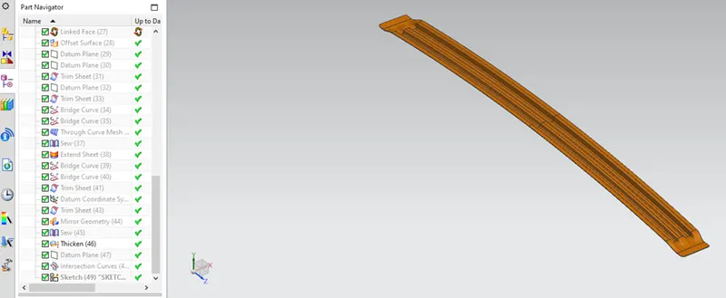
Bow roof-1 & 2
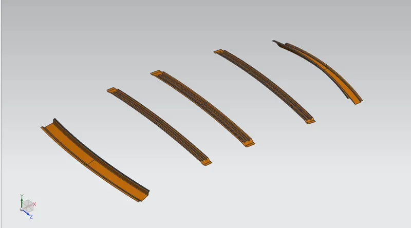
views
Assembly
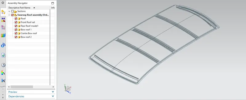
Split view
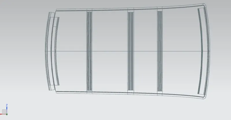
Bottom view
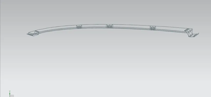
Side view
Analysis
1. Curvature Study
(It is done to justify the positioning of the Bow Roofs. There are mainly three criterions to fulfil)
- Heat Distortion Criteria
- Snow Load Criteria
- Roof Crush test
Note: Roof Crush Testing is done only after the part or prototype is manufactured in physical conditions.
2. Section Modulus
- Draft Analysis
1.1 Heat distortion
W = [1.73 x 10^(-3) x L] + [1.85 x 10^(-8) x (R^2)/t] + [ 1.10x10^(-3) x l] - 2.68
Judgement Condition: OK< 2.7> 3.1
Where,
L = Roof Length in X-Direction [mm](Roof dimension in 0-Y) R = Roof curvature
R = 2(Rx*Ry)/(Rx+Ry) Rx = X curvature
Ry = Y curvature
t = Roof plate thickness [mm] l = Bow Roof Span [mm]
Steps :
- From 0-Y axis, at -3Y about distance 300mm is drawn parallel on the perpendicular Then, 100 mm lines were offset to either side of -3Y line. Then centre lines were determined and drawn between each adjacent roof rail edges. Necessary intersection points were marked on the sketch
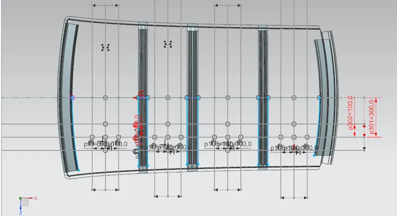
- Project the intersection points to roof surface. Join the projected points using three point arcs and find the Rx and Ry
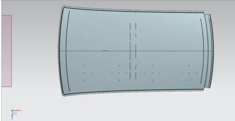
|
NO. |
BOWS |
Rx |
Ry |
R |
I |
L |
t |
R^2/t |
W |
OK/ NG |
|
1 |
FR&BOW1 |
5704.77 |
2926.46 |
3868.459 |
505.3 |
2022.3 |
0.75 |
19953300 |
1.743 |
OK |
|
2 |
BOW1&CR |
4851.03 |
6684.46 |
5622.043 |
299.6 |
2022.3 |
0.75 |
42143156 |
1.927 |
OK |
|
3 |
CR&BOW2 |
3980.73 |
10564.56 |
5782.581 |
457.1 |
2022.3 |
0.75 |
44584324 |
2.146 |
OK |
|
4 |
BOW2&RR |
3228.89 |
14928.84 |
5309.428 |
392.3 |
2022.3 |
0.75 |
37586700 |
1.945 |
OK |
Heat distortion criteria (All units are in millimetres)*
Thus, all values of W< 2.7. So according to the heat distortion criteria, current positioning of all the bow roofs are found ‘OK’.
1.1 Snow load Prediction formula;
Qr = [Iy x t2+ / *α x s x *(Rx + Ry)/2+2 x 10-8]
Judgement condition = Qr ≥ 3.1 Where,
α = My x Lx2 x 10-12 , My = Y(Ly-Y)
My = Y(Ly-Y)
250 ≤ s ≤ 380
t = Roof plate thickness [mm]
Ly = Distance between the front and rear roof Rails on the Vehicle along with 0Y [mm]. Length of Roof panel with the centre point between Roof rail Front /Rear as the front and rear reference point. Lx = Distance between the Left and Right end of the roof on the Roof BOW [mm]
Width of the roof panel exposed on the surface.
Y = Distance from front Roof Rail to Roof BOW [mm]
s = Distance for which Roof BOW bears divided load [mm], s = L1/2 + L2/2 Iy = Geometrical moment of inertia of Roof BOW (Y cross-section) [mm4]
Rx = Lateral direction curvature radius of roof panel Y cross-section on Roof BOW [mm]
Roof panel curvature Radius of the Length Lx in Front view
Ry = Longitudinal Direction curvature radius of the Roof panel X cross-section on Roof BOW [mm]
Roof panel X curvature radius of length s in Side view
Steps followed:
- At 0-Y axis on perpendicular plane to roof as shown in fig. draw 100 mm lines offset to either side of 0Y axis line. Now centre lines are drawn between each adjacent roof rail edges respectively. Intersection points are marked on the
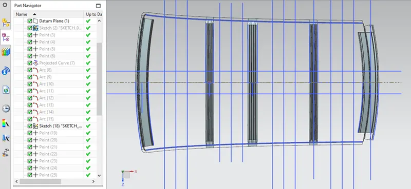
- Project the intersection points in the sketch to roof
- Join the projected curves using arc curve and measure the minimum radius and linear
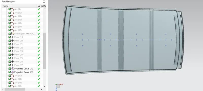
α and S
|
NO. |
BOWs |
α |
My |
Lx |
Y |
Ly |
S |
L1 |
L2 |
|
1 |
FR&B1 |
1.090 |
846697.0 |
1134.42 |
591.91 |
2022.3 |
483.905 |
591.91 |
375.90 |
|
2 |
B1&CR |
1.200 |
1021571.8 |
1085.92 |
967.81 |
2022.3 |
441.82 |
375.90 |
537.74 |
|
3 |
CR&B2 |
0.800 |
781094.40 |
1061.07 |
1505.55 |
2022.3 |
517.84 |
537.74 |
497.95 |
All dimensions are in mm*
Snow load criteria
|
NO. |
BOWs |
Iy |
α |
S |
Rx |
Ry |
t |
Qr |
OK/NG |
|
1 |
FR&B1 |
6087 |
1.090 |
483.905 |
4353.56 |
2876.72 |
0.75 |
49.70 |
OK |
|
2 |
B1&CR |
3192 |
1.200 |
441.820 |
3795.10 |
6614.79 |
0.75 |
12.47 |
OK |
|
3 |
CR&B2 |
3016 |
0.800 |
517.840 |
4279.00 |
11128.02 |
0.75 |
6.280 |
OK |
(Judgement condition = Qr ≥ 3.1) All dimensions are in mm*
Conclusion:
Thus, from the values that obtained, we can see that Qr always greater than 3.1. So, we can assume that the designed roof reinforcement rails and bow roof are at proper positions with sufficient strength and safe for snow load condition and found OK.
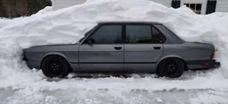
Snow accumulated over a car during winter season
2. Section modulus
Section modulus is a geometric property for a given cross-section used in the design of beams or flexural members. Other geometric properties used in design include area for tension and shear, radius of gyration for compression, and moment of inertia and polar moment of inertia for stiffness. Any relationship between these properties is highly dependent on the shape. There are two types of section moduli, the elastic section modulus and the plastic section modulus. For general design, the elastic section modulus is used, applying up to the yield point for most metals and other common materials.
The elastic section modulus is defined as;
S = I / y Where,
S = Section modulus
I = second moment of area (or area moment of inertia, not to be confused with moment of inertia)
y = Distance from the neutral axis to any given fibre. It is often reported using y = c, where c is the distance from the neutral axis to the most extreme fibre.
Section moduli of various roof rails are as follows;
2.1 Front roof rail
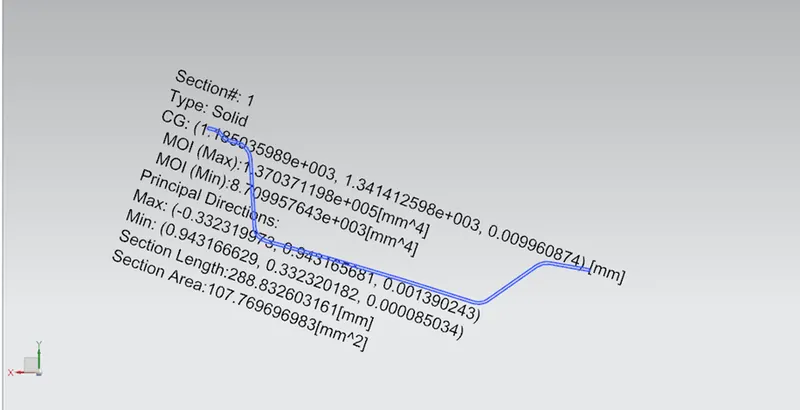
S= I/Y
=(8.709 x 10^3mm^4)/59.50mm = 147.6101mm^3
2.2 Bow Roof 1
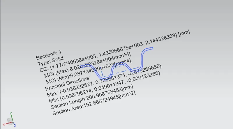
S = I/y
= (6.087 x 10^3mm^4)/34.95mm
= 174.163^3
2.3 Centre roof rails
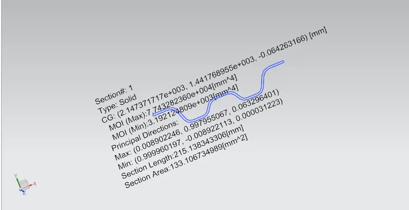
S = I/y
= (3.192 x 10^3mm^4)/42.47mm
= 75.158mm^3
2.4 Bow Roof 2
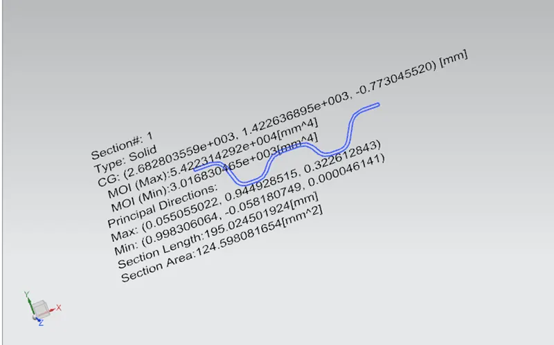
S = I/y
= (3.0168 x 10^3mm^4)/36.5mm
= 82.652mm^3
2.5 Rear roof rail
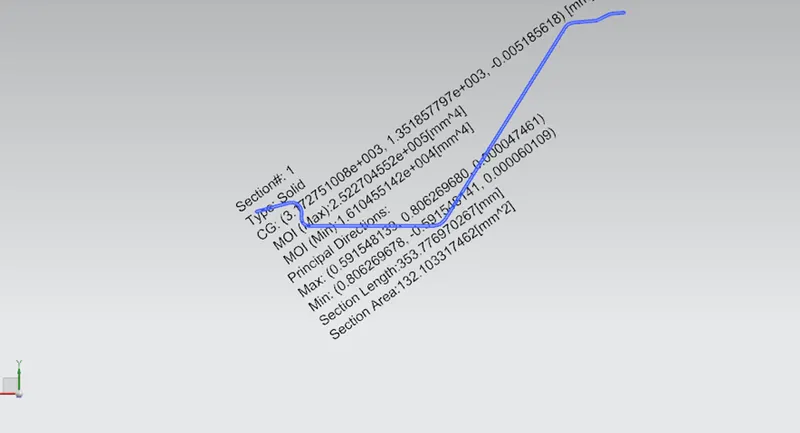
S = I/y
= (1.610 x 10^4mm^4)/74.072mm
= 217.35mm^3
2.6 Roof outer panel
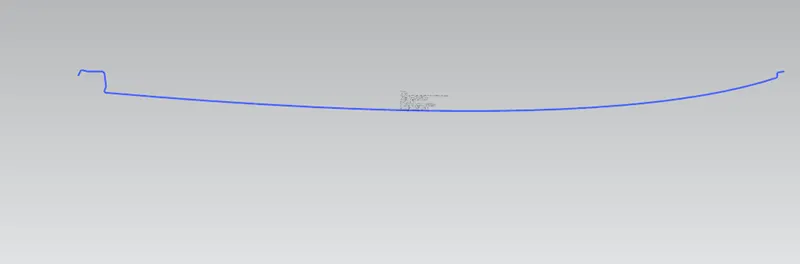
S = I/y
= (1.767x10^6mm^4)/1066.145mm
= 1657.3730mm^3
(NOTE: We can improve the section modulus by modifying the cross sectional design values within the limited ranges
Conclusion
Thus, the roof outer panel and it's reinforcement rails were designed using NX CAD 2011. At first with the given roof styling surface, I developed the outer roof panel with essential flanges on the ditch area, reinforcements such as front roof rail, two bow roofs, centre reinforcement rail with an inner bow roof and rear roof rail, with appropriate dimensions., Did a curvature study on the roof and performed necessary calculations to determine the optimal position of all the bow-roofs. Various factors influencing the roof design such as visibility criteria, head clearance, curvature study, heat distortion criteria, snow load criteria etc. were considered to determine the optimal positions of the bow roofs so that better strength and support is provided to the roof so that safety is ensured for passengers.
Roof Crush Testing is usually done only after the part or prototype is manufactured. Before that, various simulations will be performed by CAE team inorder to optimise the design.
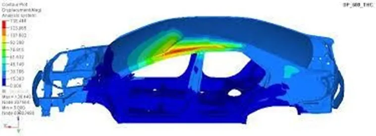
Example of roof crush software analysis
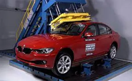
Physical roof crush test
Report submitted by: Swaroop T