Roof challenge
DESIGN OF ROOF
Objective :-
1. To perform the section modulus study for the master sections and create for the front rail roof, Rear rail roof, bow roof rail and rear roof rail
2. To create the ditch area and to perform the draft analysis.
Design Consideration :-
- Visibility Criteria
- Head Clearance
- Curvature Study
- Heat Distortion and snow load criteria
- Material Thickness
Introduction :-
Roof :-
An automobile roof or car top is the portion of an automobile that sits above the passenger compartment, protecting the vehicle occupants from sun, wind, rain, and other external elements. Because the earliest automobiles were designed in an era of horse drawn carriages, early automobile roofs used similar materials and designs.
Main Components of Roof :-
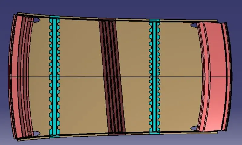
Front Roof Rail :-
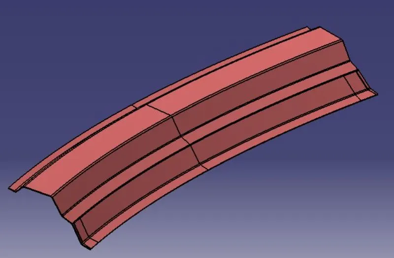
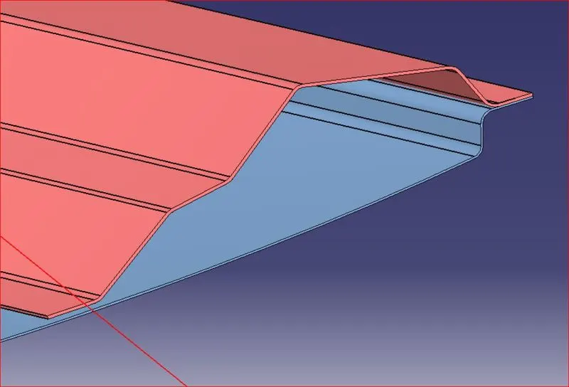
Front roof rails are used in assembly of a roof in which it provides mounting provisions to windshield glasses and changes in front roof rails influences the front visibility of passenger. The major decision factor considered is the headroom clearance. The front roof rail also provides provisions for mounting of inside rear view mirror.
Bow Roof Rail 1 :-
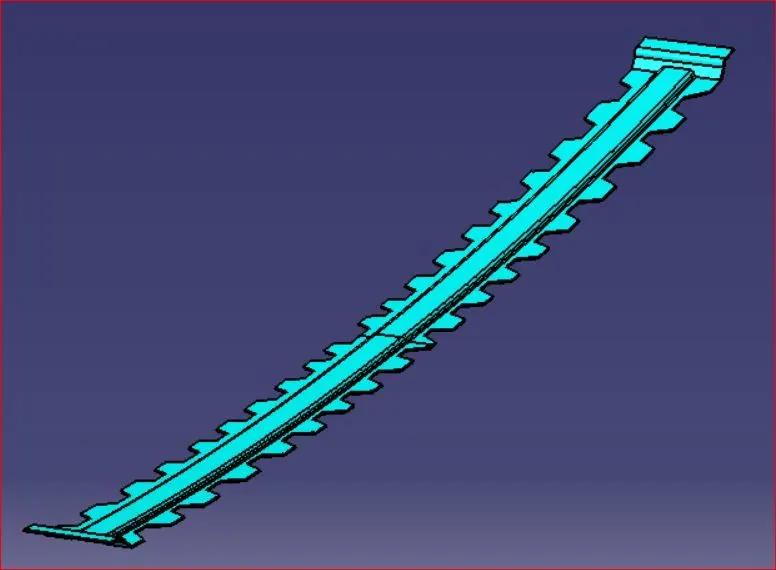
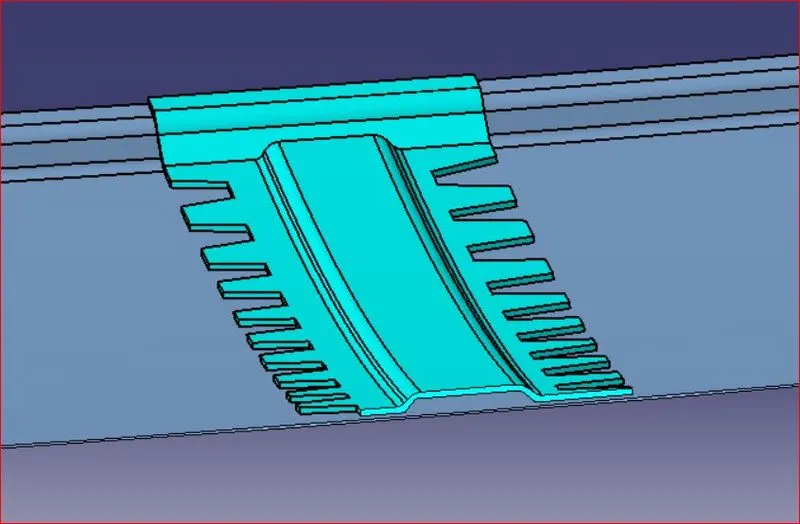
Bow roof is used to give strength it additionally added to the roof and is it joined to spot welding directly.
Center Roof Rail
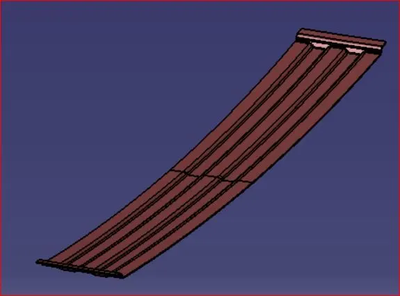
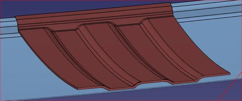
The reinforcement center is used as a cross member between LH & RH respectively. In some cases, the reinforcement center is not joined with the roof and in some other cases, it is
Bow Roof Rail 2 :-
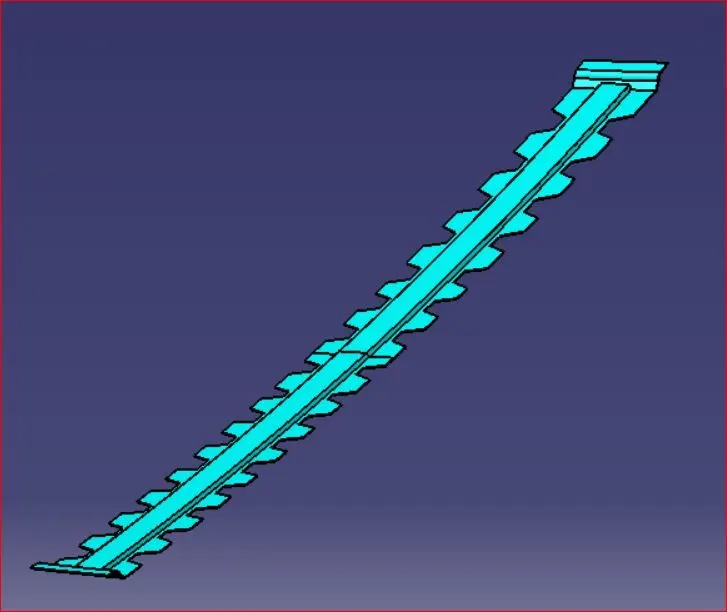
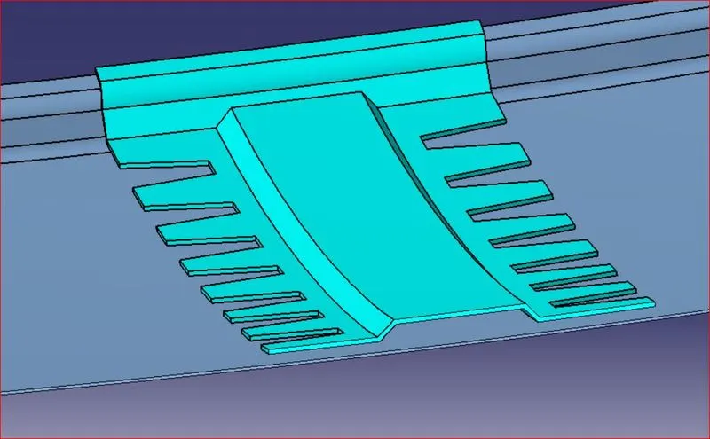
Bow roof rail 2 is used similar to bow roof rail 1 but limited extended and used for small cross sections.
Rear Roof Rail :-
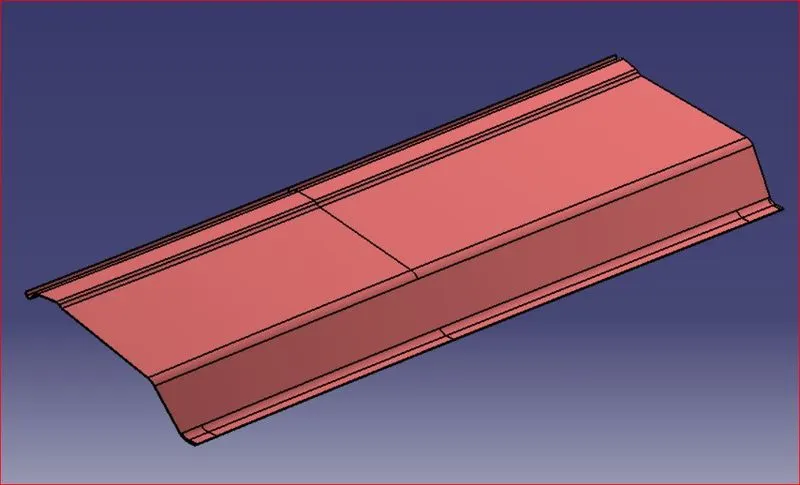
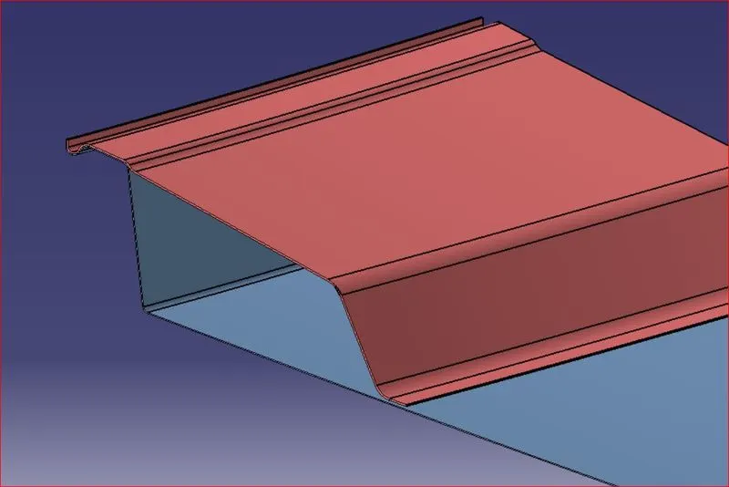
The rear roof rail is one of the most impotant component of roof assembly used for back door mounting.similar to front roof rail important design consideration include rear passenger head clearance rear visibility of the vehicle.\
Curvature Study of the roof :-

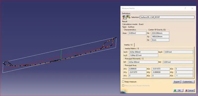
Maximum Moment of inertia :- 6.650080e+06mm4
Minimum Moment of inertia :- 100e+07mm4
MOMENT OF INERTIA :-
Front Roof Rails :-
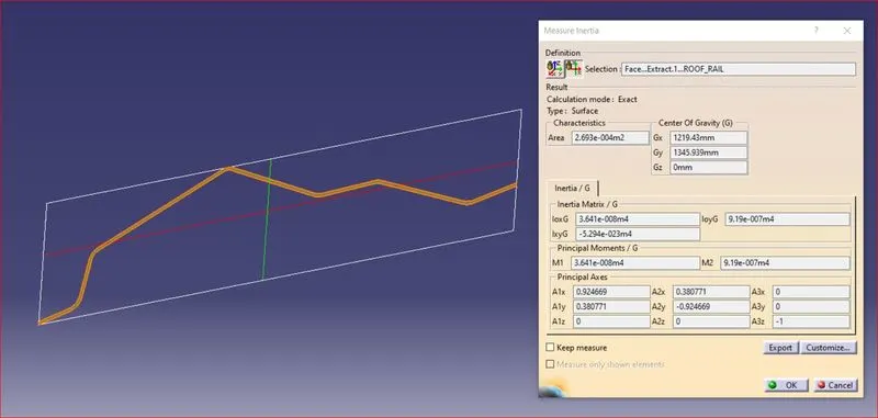
Maximum Moment of inertia :- 3.6410e+04mm4
Minimum Moment of inertia :- 9.19000e+05mm4
Center roof rails :-
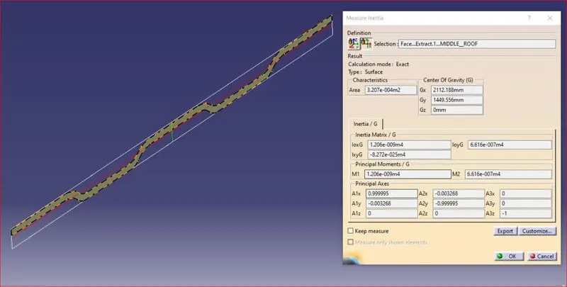
Maximum Moment of inertia :- 1.206e+03mm4
Minimum Moment of inertia :- 6.61600e+05mm4
Rear roof rails :-
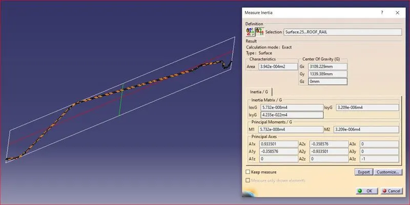
Maximum Moment of inertia :- 5.73243e+05mm4
Minimum Moment of inertia :- 3.208880e+06mm4
Heat Distortion Curvature Study :-
The Heat distortion study play an important role in Sheet metal usage. Heat distortion temp. limit above which the material cannot be used for structural application. This study is used to predict the heat distortion temperature at where the material start to soften when exposed to a fixed load at elevated temperature. In order to avoid bending/damages on roof based on heat distortion temperature, this study will predict the bow roof position on roof for strengthening of roof.
Bow–roof prediction Formula
W = [1.73 x 10^(-3) x L] + [1.85 x 10^(-8) x (R^2)/t] + [ 1.10x10^(-3) x l] - 2.68
Judgement Condition : OK< 2.7 > 3.1
Where
L = Roof Length in X-Direction[mm](Roof dimension in 0-Y)
R = Roof curvature
R = 2(Rx*Ry)/(Rx+Ry)
Rx = X curvature
Ry = Y curvature
t = Roof plate thickness [mm]
l = Bow Roof Span [mm]
| Sl no. | BOWS | Rx | Ry | R | I | L | t | (R^2/t) | w | OK/NOT OK |
| 1 | FR & 1ST | 2718.20 | 2764.5 | 2741.15 | 313.50 | 2026.10 | 0.75 | 10018570.6 | 1.35 | OK |
| 2 | 1ST & CTR | 4789.68 | 5185.33 | 4979.65 | 200 | 2026.10 | 0.75 | 33062664.3 | 1.65 | OK |
| 3 | CTR & 2ND | 4015.73 | 12100.2 | 6030.20 | 138.30 | 2026.10 | 0.75 | 48484416.05 | 1.87 | OK |
| 4 | 2ND & RR | 3300.30 | 36627.9 | 6055.02 | 306.20 | 2026.10 | 0.75 | 48884356.26 | 2.066 | OK |
Snow load Prediction formula
Qr = [Iy x t2] / [α x s x [(Rx + Ry)/2]2 x 10-8]
Note: The Qr value given over here is correct. There was a typo error in the formula given in the video.
Where
α = My x Lx2 x 10-12 , My = Y(Ly-Y)
Judgement condition = Qr ≥ 3.1
250 ≤ s ≤ 380
t = Roof plate thickness [mm]
Ly = Distance between the front and rear roof Rails on the Vehicle along with 0Y[mm]
Length of Roof panel with the center point between Roof rail Front /Rear as the front and rear reference point.
Lx = Distance between the Left and Right end of the roof on the Roof BOW [mm]
Width of the roof panel exposed on the surface.
Y = Distance front Front Roof Rail to Roof BOW[mm]
s = Distance for which Roof BOW bears divided load [mm]
s = L1/2 + L2/2
Iy = Geometrical moment of inertia of Roof BOW (Y cross-section )[mm4]
Rx = Lateral direction curvature radius of roof panel Y cross-section on Roof BOW [mm]
Roof panel curvature Radius of the Length Lx in Front view.
Ry = Longitudinal Direction curvature radius of the Roof panel X cross-section on Roof BOW [mm]
Roof panel X curvature radius of length s in Side view.
| Sl no. | BOWS | IY | a | LX | LY | y | s | Rx | Ry | t | Qr | OK/NOT OK |
| 1 | FR & 1ST | 2367.98 | 1.01 | 1125.8 | 2046.76 | 528.15 | 215.35 | 2770.34 | 2420.7 | 0.75 | 90.90 | OK |
| 2 | 1ST & CTR | 3450.34 | 0.948 | 1082 | 2046.76 | 426.78 | 184.7 | 3340.32 | 5663.2 | 0.75 | 54.69 | OK |
| 3 | CTR & 2ND | 2625.69 | 0.77 | 1047.2 | 2046.76 | 436.5 | 298.2 | 4112.56 | 9916.5 | 0.75 | 13.07 | OK |
| 4 | 2ND & RR | 0.737 | 1045.78 | 2046.76 | 412.5 | 3532.50 | 14322.8 | 0.75 |
Conclusion :-
The section modulus study for master sections and create for the front roof rail, rear roof rail, bow roof rail and rear roof rail and creation of the ditch area, and to perform the draft analysis all are done by using catia v5 software.