Roof challenge
Car Roof Design Using NX CAD
Objective
- To design the roof, including front roof rail, bow-roof rails, center roof rail and rear roof rail, taking roof styling surface as reference.
- To do a curvature study on the roof and perform calculations to determine the position of bow-roof.
- To do a section inertia study for the master sections of individual roof parts.
- To perform draft analysis on each part.
Introduction
- An automobile roofor car top is the portion of an automobile that sits above the passenger compartment, protecting the vehicle occupants from sun, wind, rain, and other external elements.
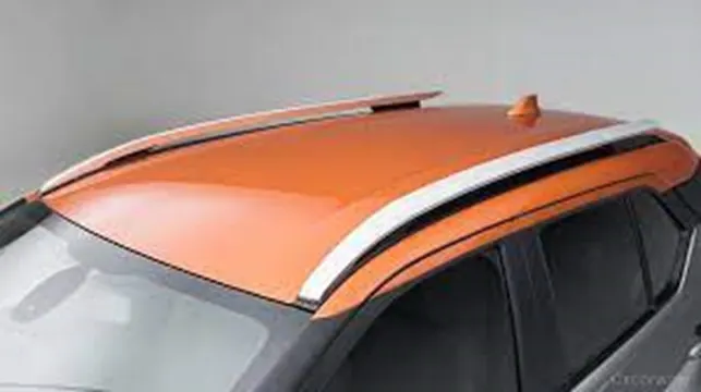
Given Data:
Bow-roof prediction formula
Design Considerations for Roof:
- Visibility criteria
- Head room clearance
- Bow roof rails position
- Heat distortion and Snow load criteria
- Draft analysis
Roof design with essential flanges and reinforcements:
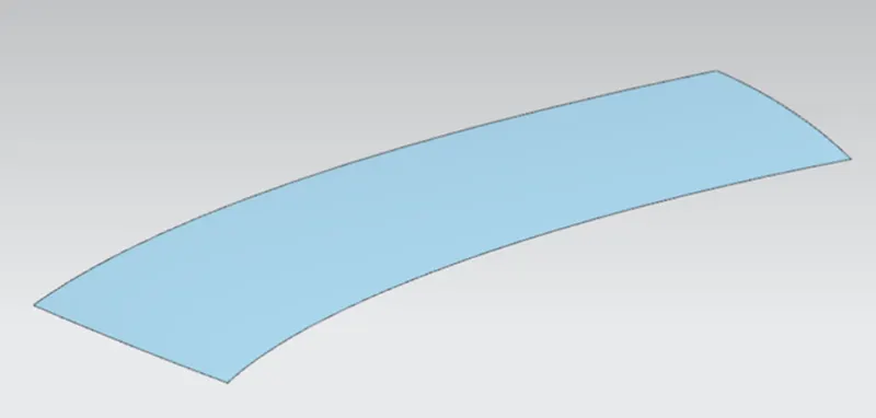
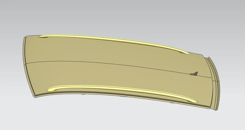
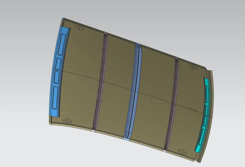
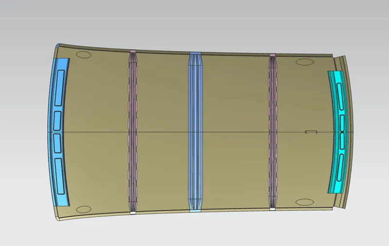
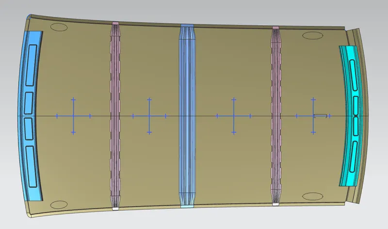
Using the styling surface, roof outer panel, front roof rail, bow-roof rails, centre roof rail and rear roof rail are designed.
a. Front ditch area
At first the front ditch area is created by referring the given parameters. In this area the front mirror gets mounted.
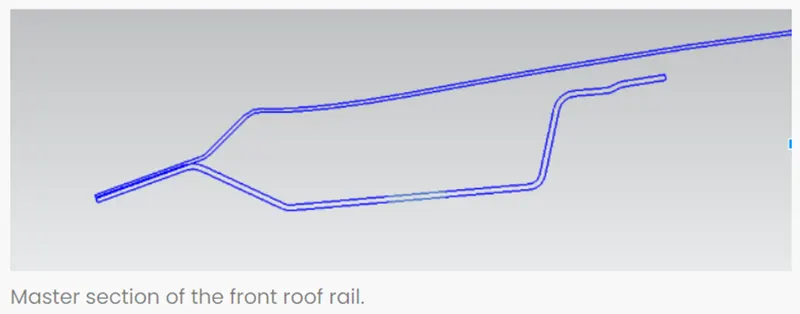
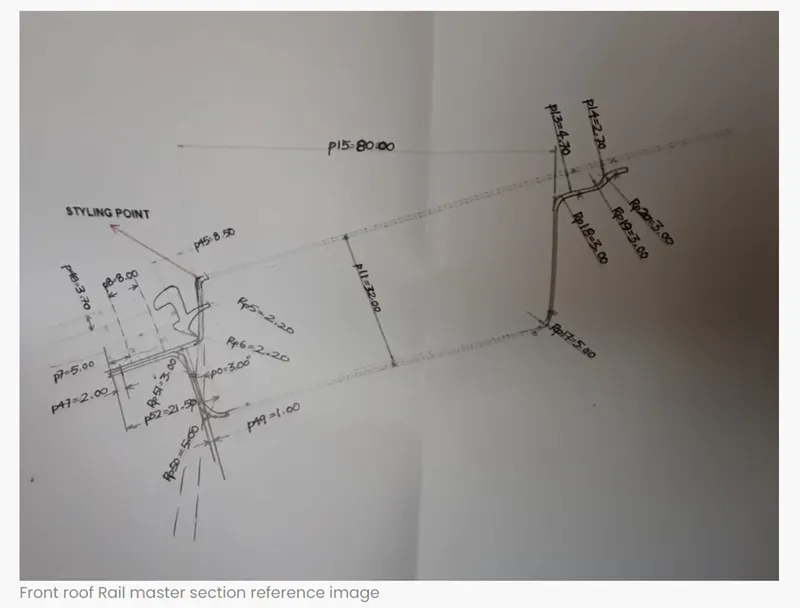
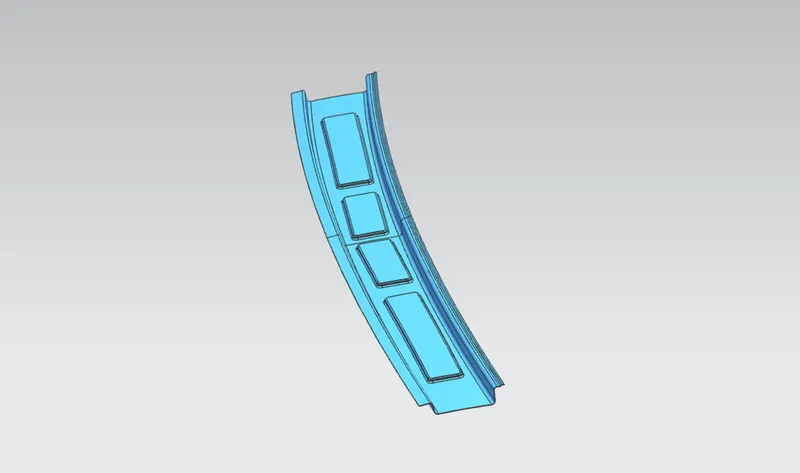
b. Front roof rail
Roof rails are considered to oppose the externally applied forces on the roof in case of accidents. When considering the parameters of roof rail, give them 60-80mm length, proper draft angle and also use embosses for increasing the strength. Front section of front roof rails spot welded to the front ditch area and other end is fixed with help of mastic sealants.
Sheet metal thickness t = 0.75mm
Embosses height = 2 < 3t
Flange length = 13.2 > 3t+R
Radius = (3mm or 5mm) > t
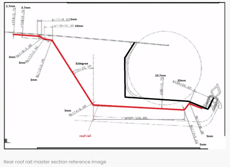
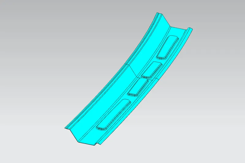
c. Rear roof rail
Roof rails are considered to oppose the externally applied forces on the roof in case of accidents. End section of the rear roof rail is spot welded with roof outer flange and other end is fixed with the help of mastic sealants.
Sheet metal thickness t = 0.75mm
Embosses height = 2 < 3t
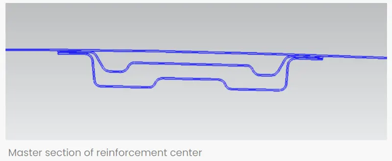
d. Centre roof rail
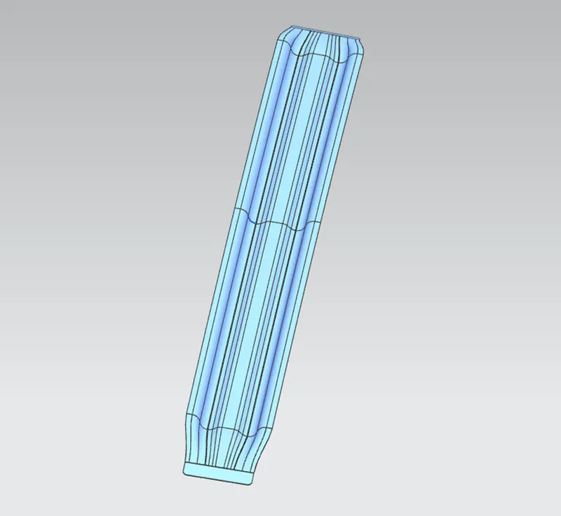
Roof rails are considered to oppose the externally applied forces on the roof in case of accidents. Considering 50% of the arc length of the styling surface, the centre roof rail is created.
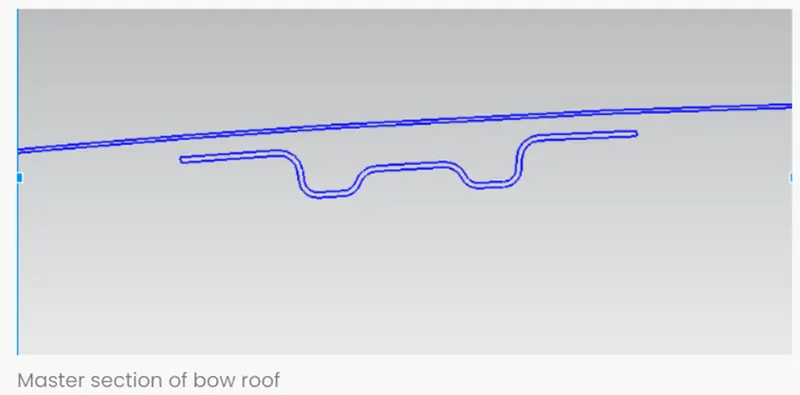
e. Bow-roof rails
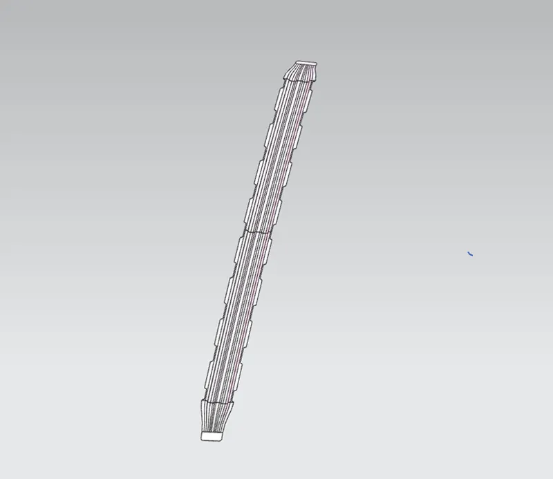
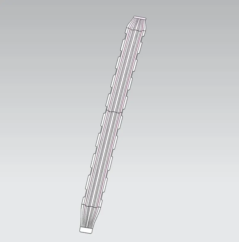
Bow-roof rails are placed in the flatter region of the roof to improve the overall strength of the roof. Here two bow-roofs are created which are placed at two different regions of the roof. Bow roofs also consists mastic points which are used to join the roof outer panel with the help of sealant. Bow-roof thickness is taken as 0.75 mm.
Bow-roof rail 1 is created by considering 33% of the arc length of the styling surface whereas bow-roof rail 2 is created by considering 75% of the arc length of the styling surface.
Bow-roof 1 and 2
Heat Distortion Criteria:
The heat distortion temperature is one heat resistance index, and is an index of the strength (elastic modulus) of a material at high temperature. The test method is a 3 point bending method, similar to the flexural test. For the flexural modulus, the breaking load is determined at a constant strain rate.
Procedure
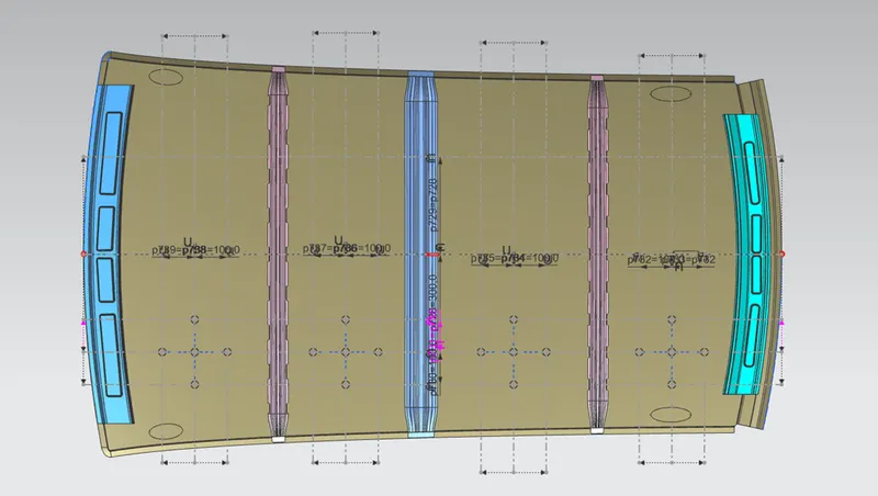
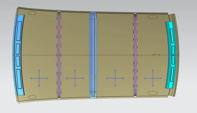
Create a centre line OY. Offset it to 300 mm up and down, this will be -3Y line. Again offset the -3Y line to 100 mm symmetrically. Now calculating the distances between consecutive roof rails, taking midpoint, draw a centre line. Again offset the centre line symmetrically 100 mm.
Create points on the intersection as shown below. Project those points on the surface and create arc using three points. After that calculate the arc radius. These arc radii are Rx and Ry in the x and y directions respectively.
Formula
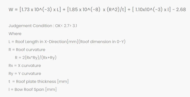
W = [1.73 x 10^(-3)*L] + [1.85 × 10^(-8) x (R^2)/t]+[1.10x10^(-3) x I] -2.68
Judgement Condition: OK <2.7> 3.1
Where,
L = Roof Length in X-Direction [mm] (Roof dimension in 0-Y)
R = Roof curvature
R = 2(Rx * Ry) / (Rx + Ry)
Rx = X curvature
Ry=Y curvature
t = Roof plate thickness [mm]
I= Bow Roof Span [mm]
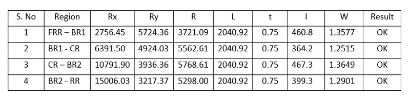
All the values in above table are in mm.
From the above results, we can conclude that the bow roofs are placed at right regions.
Snow Load Criteria:
This is the load that can be imposed by the accumulation of snow and is more of a concern in geographic regions where snowfalls can be heavy and frequent.
Procedure
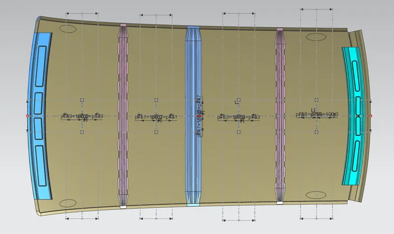
Create a centre line OY. Offset it to 100 mm symmetrically. Now calculating the distances between consecutive roof rails, taking midpoint, draw a centre line. Again offset the centre line symmetrically 100 mm.
Create points on the intersection as shown below. Project those points on the surface and create arc using three points. After that calculate the arc radius. These arc radii are Rx and Ry in the x and y directions respectively.
Formula
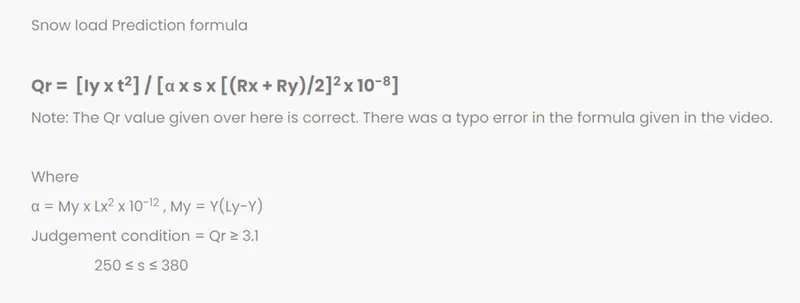
Qr= [Iy x t^2] / [ a x s x [(Rx+ Ry)/2]^2 x 10^(-8) ]
Where,
a = My x Lx² x 10^-12, My = Y(Ly-Y)
Judgement condition = Qr >= 3.1 , 250 <= s <= 380
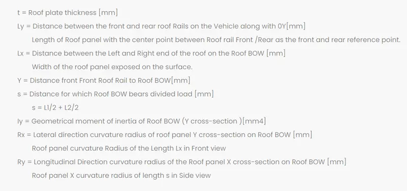
t = Roof plate thickness [mm]
Ly = Distance between the front and rear roof rails on the vehicle along with OY [mm]
Length of Roof panel with the centre point between roof rail Front/Rear as the front and rear reference point
Lx = Distance between the left and Right end of the roof on the roof bow [mm]
Width of the roof panel exposed on the surface.
Y = Distance from front roof rail to roof bow mm
s = Distance for which roof bow bears divided load [mm]
S = L1/2+L2/2
ly = Geometrical moment of inertia of roof bow (Y cross-section )[mm4]
Rx = Lateral direction curvature radius of roof panel Y cross-section on roof bow [mm]
Roof panel curvature radius of the length Lx in Front view
Ry = Longitudinal direction curvature radius of the roof panel X cross-section on roof bow [mm]
Roof panel x curvature radius of length s in side view
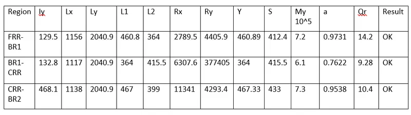
All the values in above table are in mm.
From the above results we can conclude that the roof structure passes the snow load condition.
Moment of Inertia:
Front roof
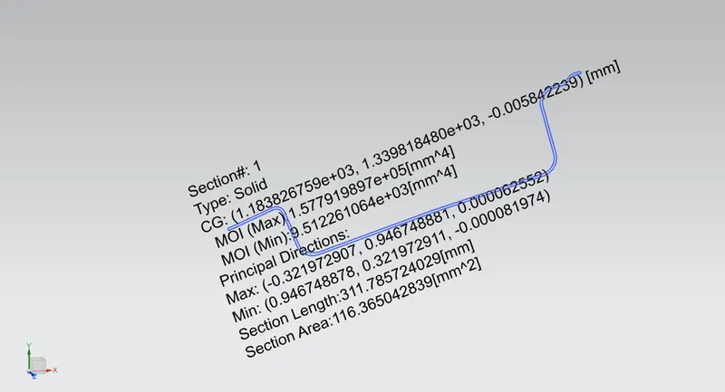
Bow-roof 1
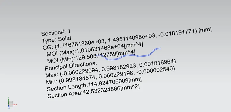
Bow-roof 2
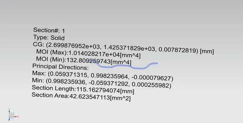
Centre roof
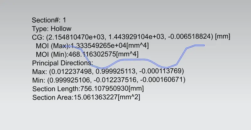
Rear roof
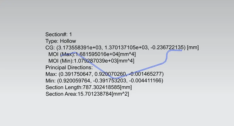
Draft Analysis:
The Draft Analysis command enables you to detect if the part you drafted will be easily removed. This type of analysis is performed based on colour ranges identifying zones on the analysed element where the deviation from the draft direction at any point, corresponds to specified values.
Minimum draft angle is 7 degree is considered for analysis. Green colour show positive draft angle of the part more than 7 degree.
Roof outer panel
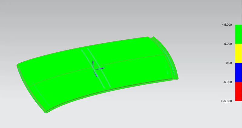
Front roof rail
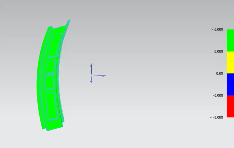
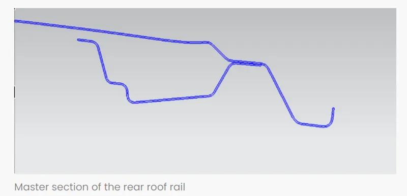
Rear roof rail
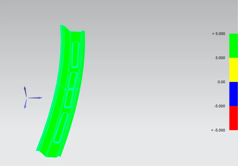
Bow-roof rail 1
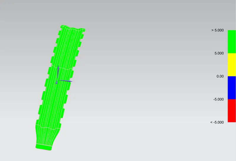
Bow-roof rail 2
Centre roof rail
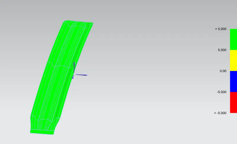
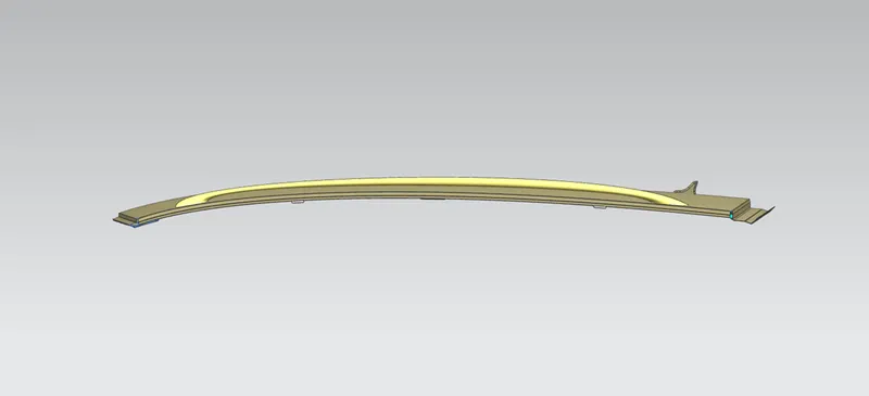
Views of Roof: