Roof challenge
CAR ROOF DESIGN
Objective :
The main objective of the project is to create the roof of the car with front roof rail and rear roof rail. Also, to create the bow roof rail reinforcements to give extra strength to the roof structure.
To calculate the Heat distortion and Snow load criteria on the model created. Also create the section inertia on the all roof sections.
To create the draft analysis on the all roof rails to satisfy the sheet drawing standards.
Theory :
Roof -
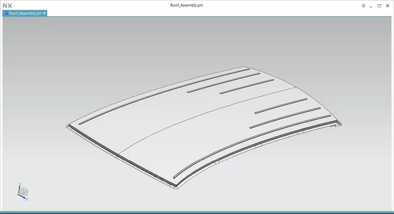
An automobile roof or car top is the portion of an automobile that sits above the passenger compartment, protecting the vehicle occupants from the sun, wind, rain and other external elements or environment conditions.
The roof is joined with the pillars on all sides, and the roof is reinforced with the front roof rail, rear roof rail and bow roofs. The rails are joined with the roof with the help of mastic sealant because we don't want to disturb the aesthetic look of roof surface.
The below picture shows the typical internal parts of the Hyundai car roof.
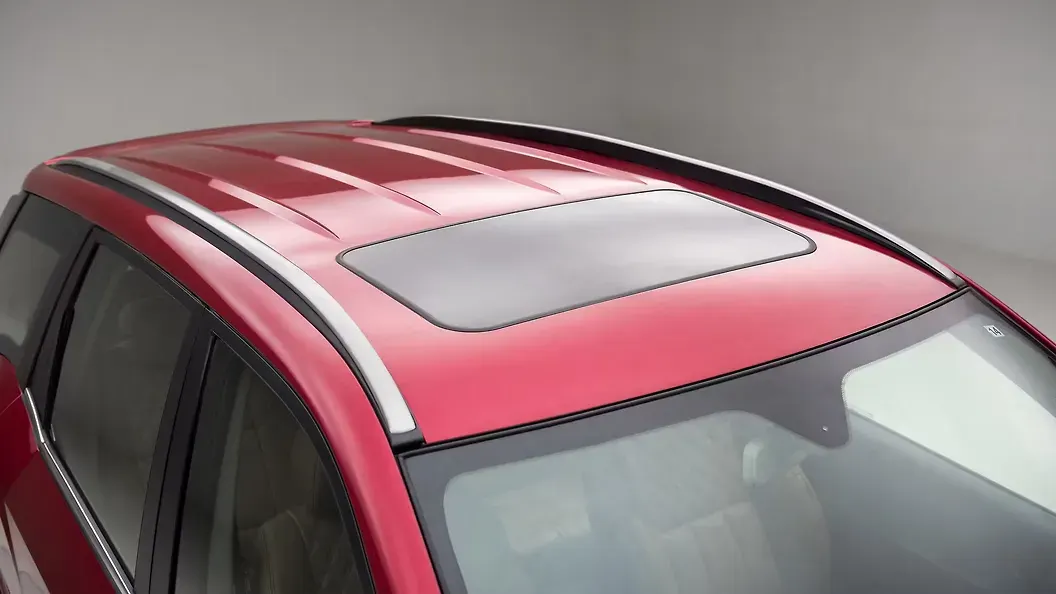
The roof design is depends on the following considerations
Design requirements of the roof
The roof assembly must be consists of the support components such as front roof rail and rear roof rail at front and rear ends. These rails connected with the pillar and give the support to the roof.
The center reinforcement is located at the center of the roof structure and is connected to the b-pillar of the BIW structure, which gives the strength to the flat surface of the roof.
Bow roofs are added to the roof as required depending on the length of the roof, which provide extra strength to the roof and to support its curvature.
Components of the roof
The roof consist of the following support sections
- Roof
- Front Roof Rail
- Rear Roof rail
- Bow Roof
- Reinforcement Roof Center
Functional requirements
- Protect the occupants from the environmental conditions
- To meet the roof crush regulations
- To contribute the structural performance of the body
- To maintain the dimensional accuracy of the body
Roll Over Test regulations and requirement
The rollover test conducted by NHTSA subjects vehicles to a handling maneuver called a fishhook, which is a term used for a quick left-right turn at speeds ranging from 35 to 50 miles per hour. The operation is a simulation of the driver overdoing the vehicle steering, usually happens during emergency situations.
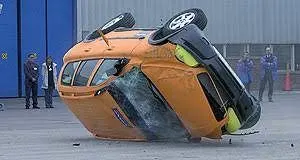
Roof crush test
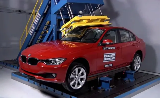
To measure the roof strength of a vehicle, IIHS has a metal plate pushed against one corner of a vehicle’s roof at a constant speed. The maximum force sustained by the roof before five inches of crush is compared to the vehicle’s weight. From there, IIHS calculates a strength-to-weight ratio.
Joining techniques
Joining of the roof with the rails, it completely depends on the position of joint. If the joining place is not visible from the outside, it will be joined with the spot welding. The below shows the laser brazing in Body-in-White.
For the case joining bow rails with the roof, mastic sealant is used because using spot weld there will disturb the aesthetic look of the roof.
Gap and Flushness requirements
The gap, gap parallel (equal distance between two gaps over a distance) and flush are the terminologies involved in automotive industry which influences the customer appeal. The gap and flush measurements of side closure are shown in the below picture.
The gaps and flushes are given to the hood of the car with fender and sidewall by adjusting the hinge and striker during assembly.
In case of an automotive design, gap and leveling between the adjacent parts, known as gap and flushness, respectively, can be cited as examples of aesthetic dimensional requirements that influence customer's perception of quality
Procedure :
Extract the roof surface from the given body and untrim it. Now trim the untrimmed surface with the extracted surface.
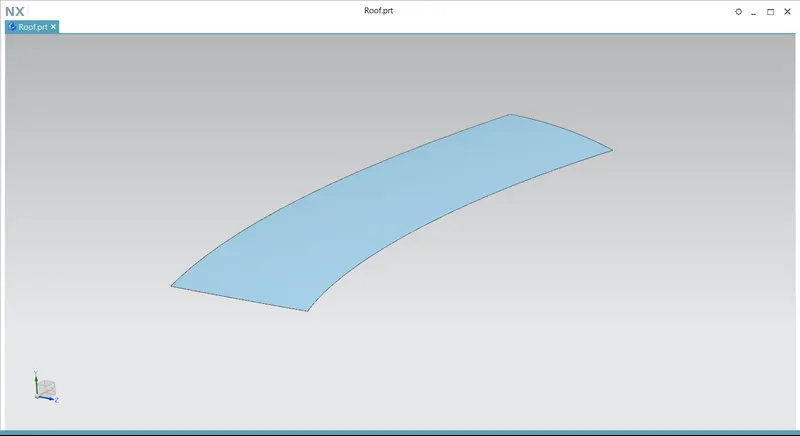
Roof -
Create the ditch area around the roof of the car and thicken it by 0.75 mm. Create the ditch areas as mentioned in the master sections of the front roof rail and rear roof rail.
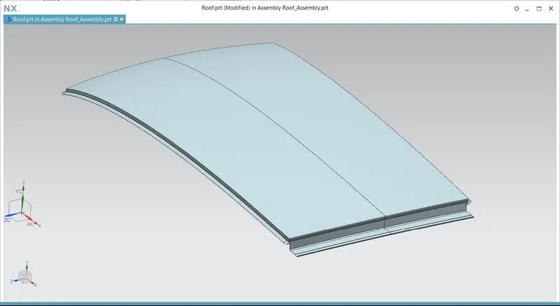
Front Roof Rail -
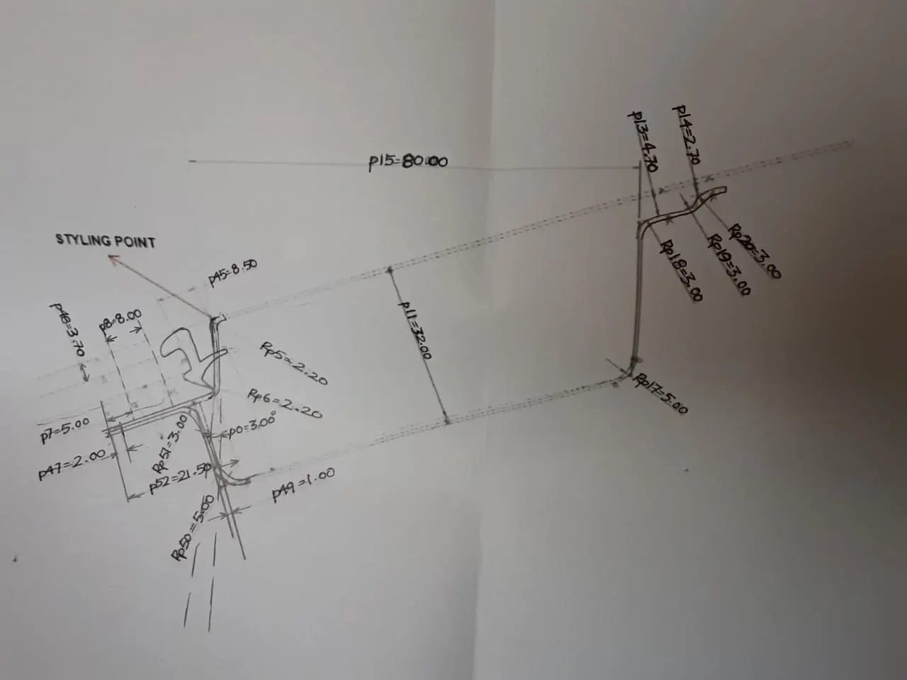
Create the front roof rail with reference of the given roof surface area. Follow the master section given to create the front rail. Also, create the embosses to add extra strength to the rails. The roof rail maintains the clearance of 0.2 mm at the ditch area side to facilitate spot welding. On the other side, a clearance of 5 mm is maintained to accommodate the mastic sealant application.
Both the front roof rail and rear roof rails are designed by taking the consideration of headroom clearance and visibility criteria. The both ends of the front roof rail are connected with A-pillar on both sides, and they are fastened or spot welded together
Rear Roof Rail -
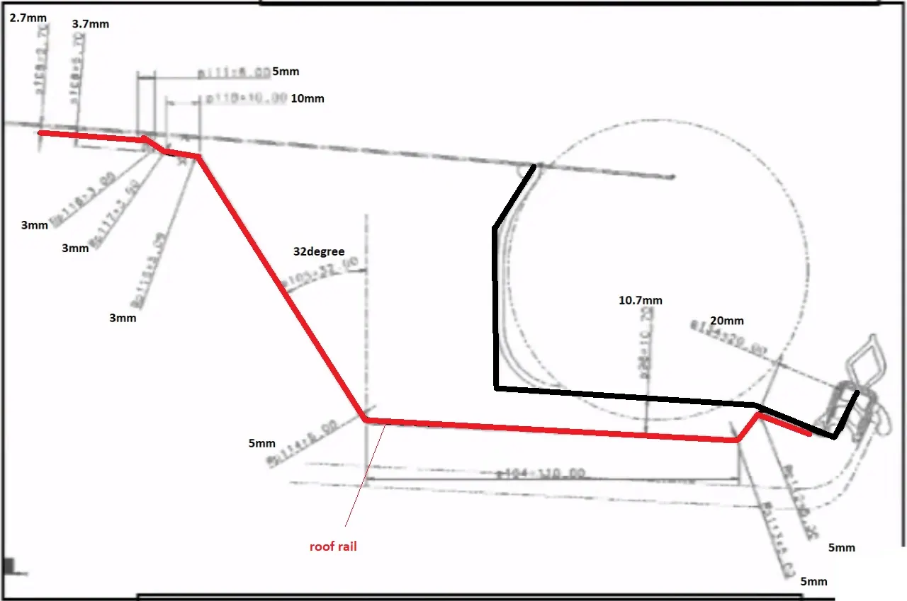
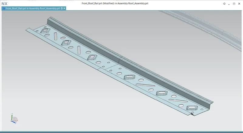
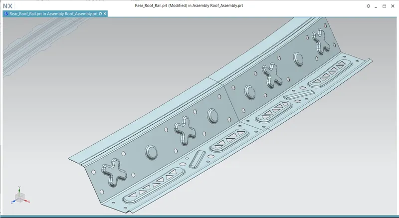
Create the rear roof rail by taking the given roof as the reference. Follow the master section to create the rear roof rail. Add the embosses on the face of the rail to give strength to the rail. The rear roof rail maintains a gap of 0.2 mm on the ditch area side where spot welding is done. On the other side, it is joined with the roof with mastic sealant.
The rear roof rail is designed in a manner that meets the headroom clearance and rear visibility criteria. The rail is connected to the c-pillar in case of small vehicle or to d-pillar in case of longer vehicles.
Bow Roof rail -
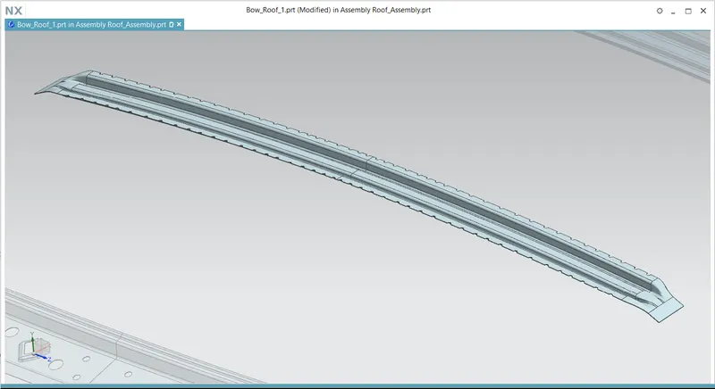
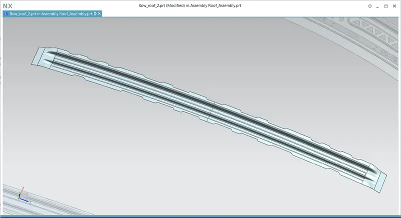
Create a pair of bow roof rails to support the roof. There is no limitation on creation of bow roof rails. It's all about the cost adding strength required strength to the roof and also cost reduction. So, one or more bow roofs are used depending upon the length of the roof. The bow roof rails improve the torsional stiffness and load bearing capacity of the roof.
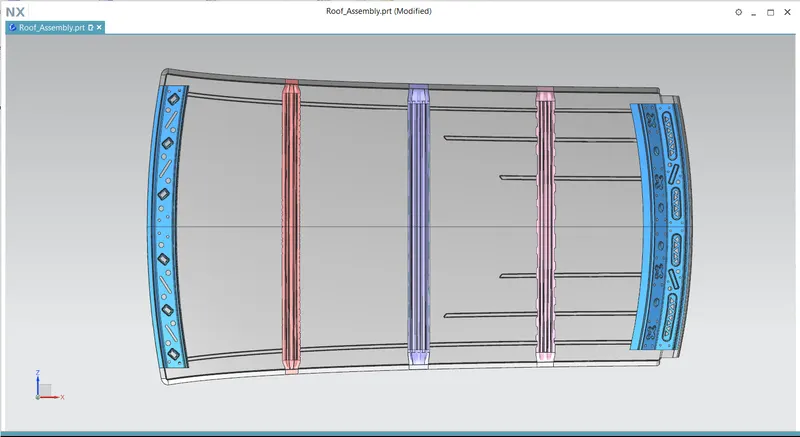
Here, I have used two bow roofs, one after the front roof rail and the other is between the center reinforcement and the rear roof rail.
Reinforcement center -
They consist of two individual parts, such as reinforcement and the center roof rail. The reinforcement center is placed at the center of the roof so that connecting the b-pillars of the both side and also which improves the roll-over resistance of the car. The reinforcement center effectively supports the flat area of the roof.
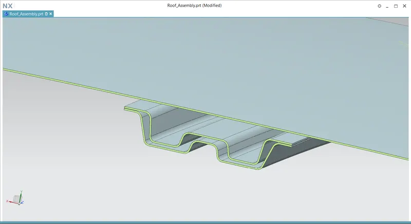
The below picture the shows the complete assembly of the roof with all support structures
Roof Bow Calculations
Heat Distortion Criteria
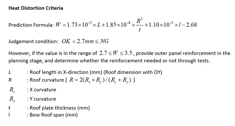
To calculate the heat distortion criteria, first we have to find the x and y curvatures. For that, we have to follow the below steps.
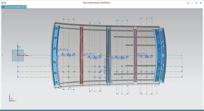
- Create a sketch on the top of the roof and the draw a horizontal construction line at the center of the roof in y direction.
- Offset the center line 300 mm below and name it as -3Y line.
- From the -3Y line, offset the construction lines to 100 mm on both sides.
- Now, find the distance between the adjacent rails, and draw a line exactly at the middle of the both rails.
- Now, We got the five intersection points, create points there and exit the sketch.
- Project the points to the roof of the car.
- Finally, draw the 3D 3 point arcs with the help of that points and find the length of the arc.
Calculation table

According to the given judgement, all scenarios are satisfied.
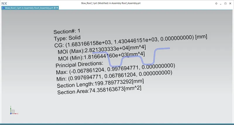
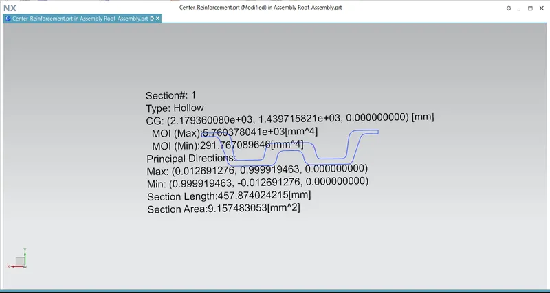
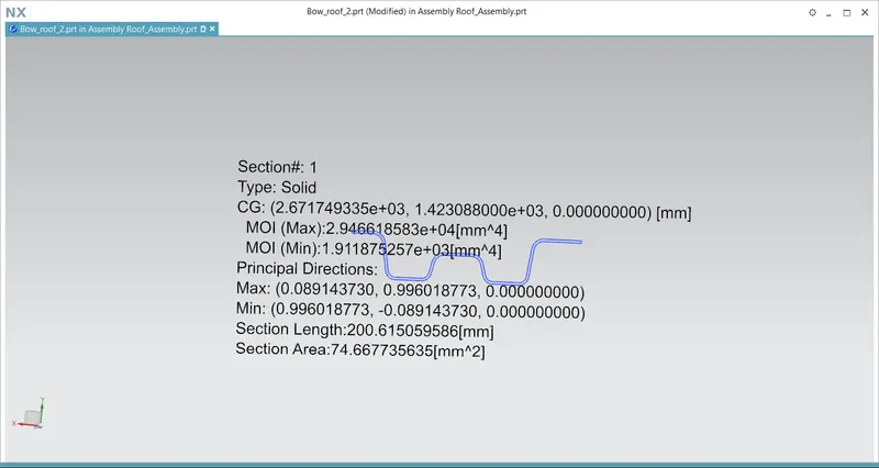
Moment of inertia
Bow roof 1 -
Center reinforcement -
Bow roof 2 -
Snowed condition
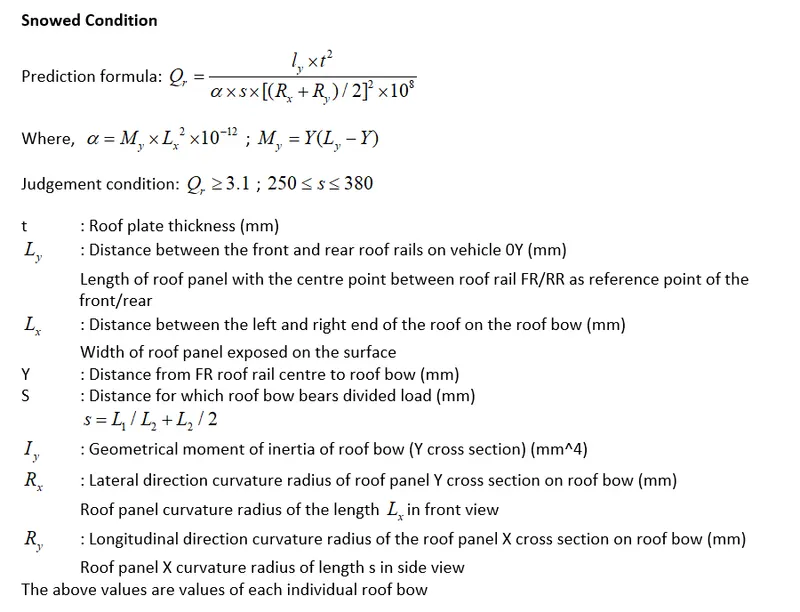
The snow load condition calculation is similar to the heat distortion. Here we have to follow the following steps to draw the reference sketch
- Create the sketch on the top of the roof and draw a horizontal line at the center of the roof.
- Offset this center line 100 mm on both sides.
- Draw the vertical lines at exactly at the center of the two adjacent rails.
- Offset this lines to 100 mm on both sides. Convert all lines into construction lines.
- Create the intersection points between the lines and project those points to the roof.
Calculation table
Create the calculation table by obtaining all the values

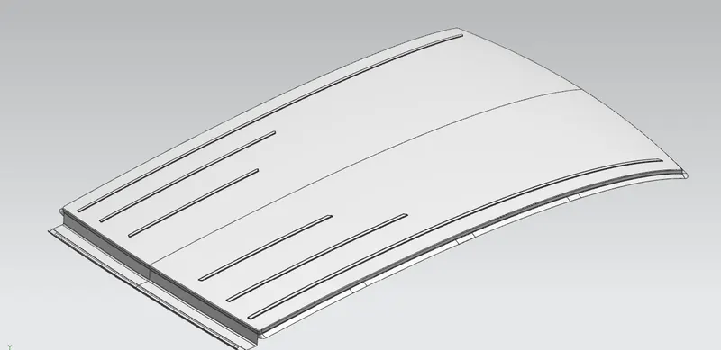
From the obtained results, it has been observed that one of the Qr values should not satisfy the judgement condition. So the model can be passed over to the styling team to change the curvature or position of bow roof rails are changed towards the weaker sections or embosses are created on the roof to improve the strength.
To improve the strength in the weak sections, I have created the embosses on the rooftop
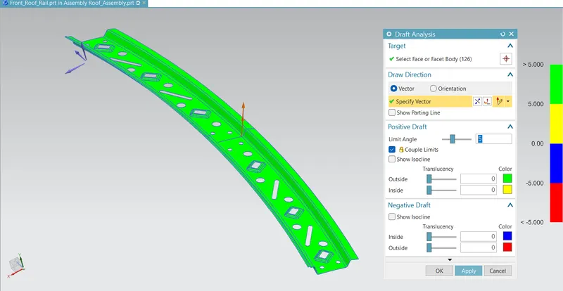
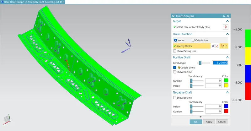
Draft analysis
The draft analysis is done on the all roof structures with 3 to 5 degrees.
Front roof rail -
Rear roof rail -
Bow roof rail 1 -
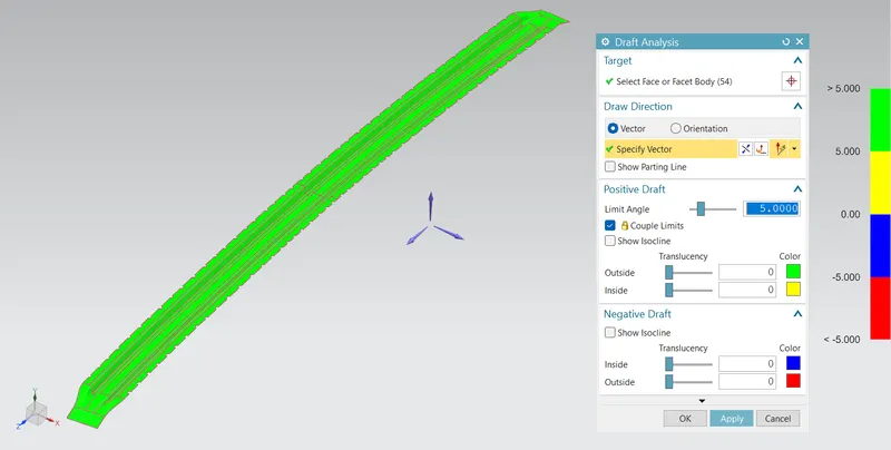
Center roof rail -
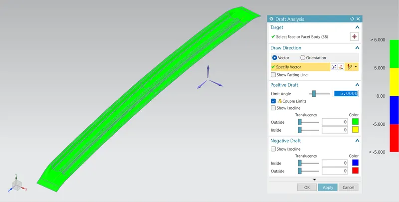
Center reinforcement -
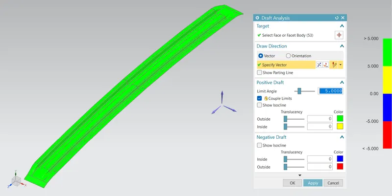
Bow roof rail 2 -
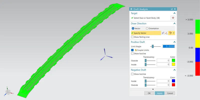
Roof -
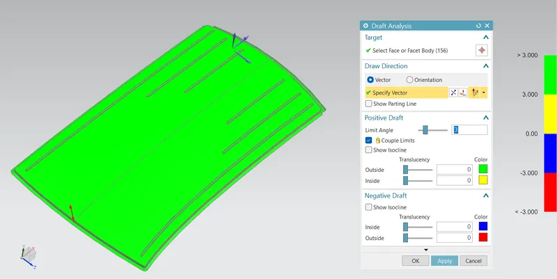
Conclusion :
The roof of the car with front roof rail and rear roof rail are created from the given class a surface from the styling team. Also, bow roof rail reinforcements are created to give extra strength to the roof structure.
Heat distortion and Snow load criteria on the model created and feasibility of model is validated. Section inertia on all the roof sections is done and moment of inertia is calculated.
The draft analysis is done on all roof rails to satisfy the sheet drawing standards.