Roof challenge
ROOF
Vehicle roof is the top part of the vehicle over the traveler compartment. Its fundamental capacity is to shield the travelers from outer components to go into traveler compartment and security perspective connected with turnover of vehicle during mishaps. Likewise, think about the Headroom freedom, perceivability Criteria, Windshield part.
- It is designed in such way that it would able to withstand any load or impact due to accidents or objects falling on it and other environmental factors.
- Therefore, the design is done based on standards and design intent that makes the roof withstand the strength.
- Headroom clearance plays a role in the design.
- Protecting the vehicle occupants from sun, wind, rain, and other external elements.
- Roof is connected to A-pillar, B-pillar and C-pillar to cover the front and rear door.
- Roof is supported by reinforcement bow-roof with front and back roof rail.
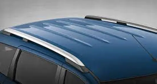
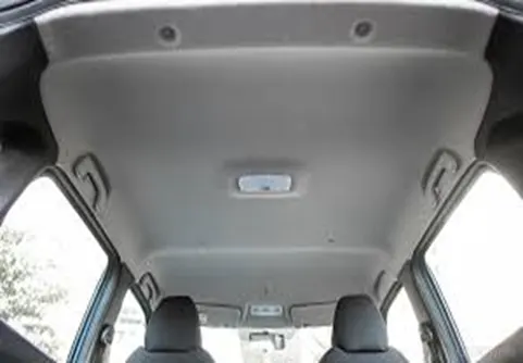
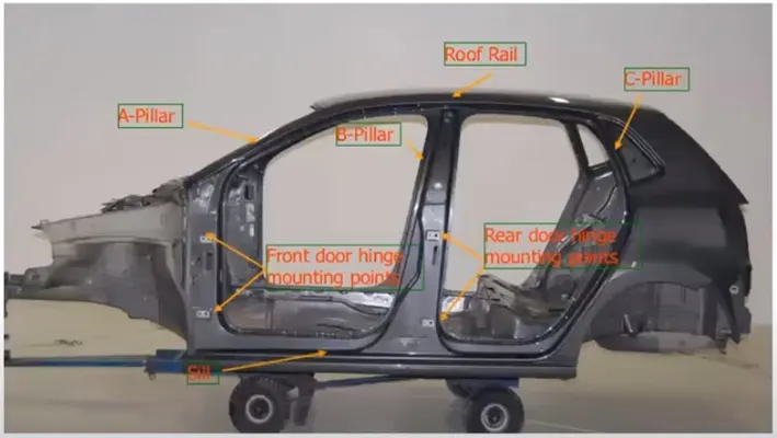
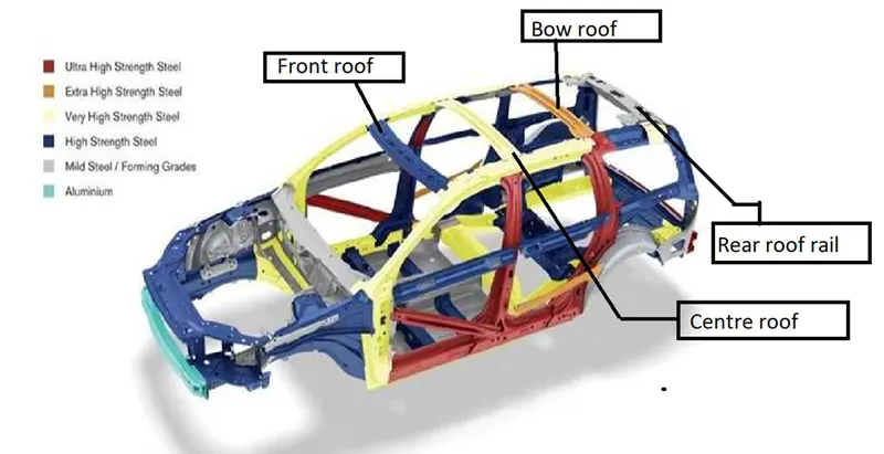
Roof Design includes:
- Front roof
- Rear roof
- Bow roofs
- Centre roof and its reinforcements

- The Roof Styling is provided for designing with the essential flanges and reinforcements.
- It is provided with the five support surfaces to strengthen the roof base from bending or deformation.
- The five flanges or reinforcements are Front Roof Rail, Back Roof Rail, Center Roof reinforcement, Bow Roof 1 and Bow Roof 2.
- Front Roof Rail
- This will act as a reinforcement for the roof front.
- We have to consider the space for mounting windshield glass, rubber around glass, rubber paste and sealant
- Thickness required are 0.75.
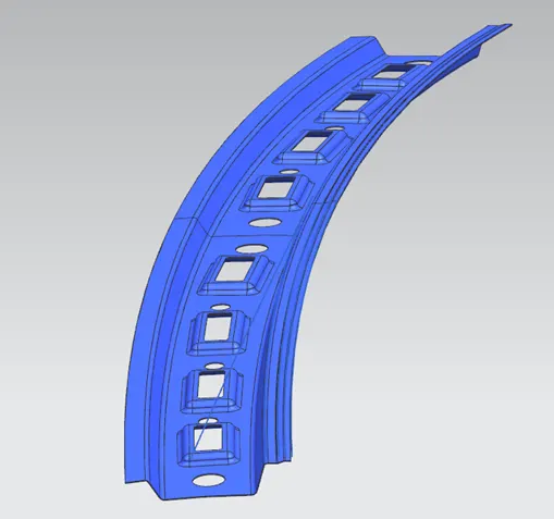
- FRR is created based on the master section standards. Styling surface is taken as reference.
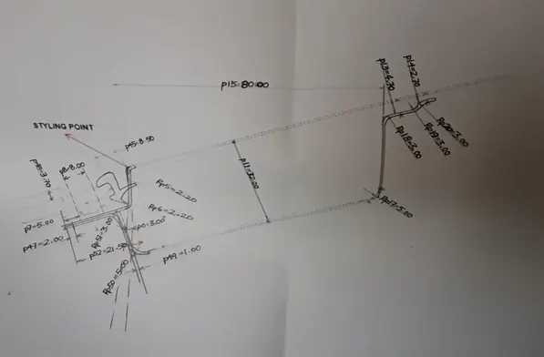
- Rear roof Rail
- This reinforcement is placed near the rear part of the roof.
- We consider the headroom clearance and rear visibility criteria.
- Minimum headroom clearance is 80mm which depends on car.
- Thickness required are 0.75mm
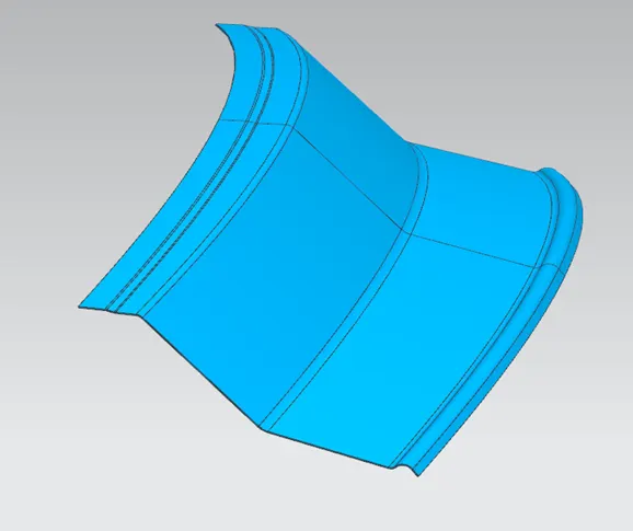
- Styling surface is taken as reference and RRR has been made as per the dimensions and angle provided with the consideration of draft angle for manufacturing feasibility.
- As per the mastic sections the rear roof is designed.
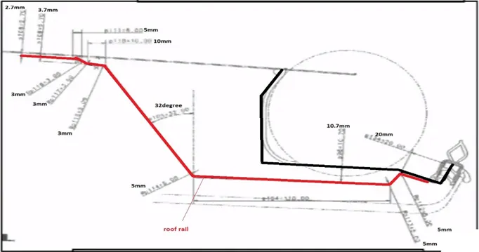
- Bow roof:
- This is placed under roof to provide strength to the roof.
- It depends on the length of the car the bow roofs are placed.
- It’s spot-welded between the bow roof and the roof.
- Its thickness is 1mm.
- The flatten surface can be find by two methods depends on heat distortion and snow load criteria.
- It is created based on the standards with 33% of arc length from styling surface in linear direction with symmetric style of design.
Here two bow roofs are used.
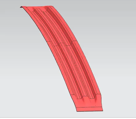
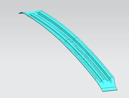
Bow roof 1 Bow roof 2
- Centre roof rail
- This is placed in center of roof to provide strength at center.
- Thickness required are 1mm.
- CR is created based on the standards with 50% of arc length from Styling surface in linear direction with symmetric style of design.
- Styling surface is taken as reference and FRR has been made as per the dimensions and angle provided with the consideration of draft angle for manufacturing feasibility.
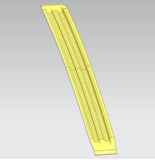
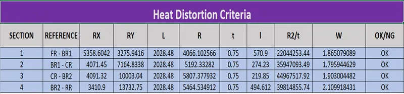
Heat distortion criteria
Formulas
W = [1.73 x 10^(-3) x L] + [1.85 x 10^(-8) x (R^2)/t] + [ 1.10x10^(-3) x l] - 2.68
Judgement Condition : OK< 2.7> 3.1
Where
L = Roof Length in X-Direction [mm](Roof dimension in 0-Y)
R = Roof curvature
R = 2(Rx*Ry)/(Rx+Ry)
Rx = X curvature
Ry = Y curvature
t = Roof plate thickness [mm]
l = Bow Roof Span [mm]
- By projecting the points the arcs are created and then measured from wchich we get Rx and Ry value.
- The L is the distance of styling roof.
- Thickness of roof is 0.75mm.
- The W value should agree the judgement conditions.
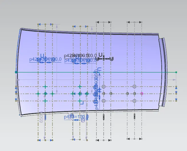
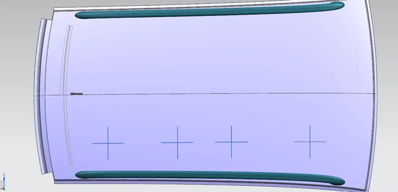
Procedure for heat distortion:
- Create a center line in OY direction and offset it to -3y(i.e. -300) distance
- From there offset 100mm on both side and make centerline between the FRR to BR1.
- Offset by 100mm on both side so we get three points on horizontal and vertical direction.
- After creating arc as shown below the Rx and Ry value is measured.
Judgement
Snow load Prediction formula:
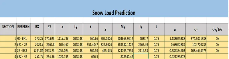
Qr = [Iy x t2] / [α x s x [(Rx + Ry)/2]2 x 10-8]
Where
α = My x Lx2 x 10-12 , My = Y(Ly-Y)
Judgement condition = Qr ≥ 3.1
250 ≤ s ≤ 380
t = Roof plate thickness [mm]
Ly = Distance between the front and rear roof Rails on the Vehicle along with 0Y[mm]
Length of Roof panel with the centre point between Roof rail Front /Rear as the front and rear reference point.
Lx = Distance between the Left and Right end of the roof on the Roof BOW [mm]
Width of the roof panel exposed on the surface.
Y = Distance front Front Roof Rail to Roof BOW[mm]
s = Distance for which Roof BOW bears divided load [mm]
s = L1/2 + L2/2
Iy = Geometrical moment of inertia of Roof BOW (Y cross-section) [mm4]
Rx = Lateral direction curvature radius of roof panel Y cross-section on Roof BOW [mm]
Roof panel curvature Radius of the Length Lx in Front view
Ry = Longitudinal Direction curvature radius of the Roof panel X cross-section on Roof BOW [mm]
Roof panel X curvature radius of length s in Side view
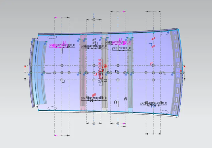
Procedure for snow load:
- Create a centerline in OY direction from there offset 100mm on both side and make centerline between the FRR to BR1.
- Offset by 100mm on both side so we get three points on horizontal and vertical direction.
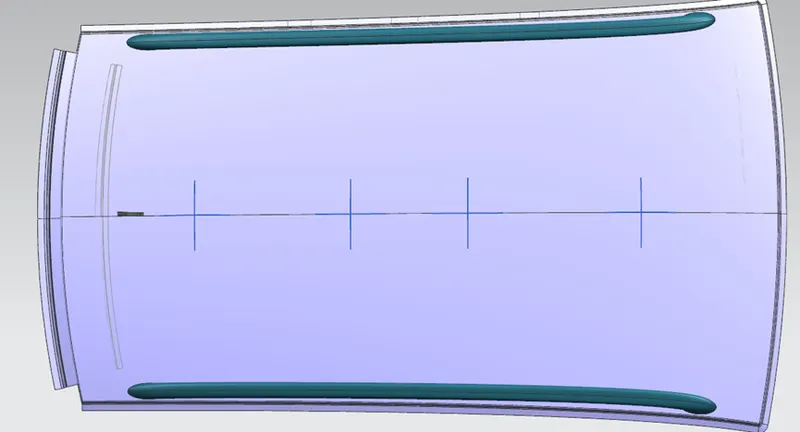
Assembly
- Using the styling surface provided of the roof the reinforcements and all the components are assembled.
- By spot welding the components of bow roof , center roof , front roof and rear roof is welded as shown below.
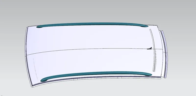
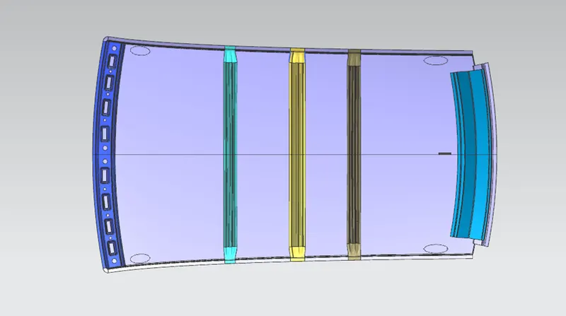
Section modulus for bow roofs and Centre roof is calculated tfor snow load criteria.
Bow roof 1
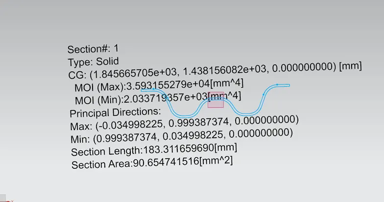
Moment of Inertia : I=2033.7mm^4
Bow roof 2:
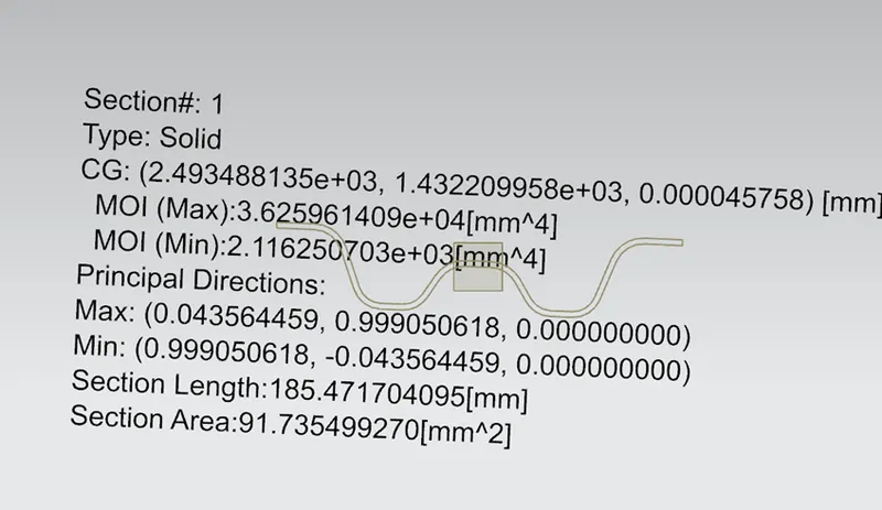
Moment of inertia: I =2116.25mm^4
Centre roof:
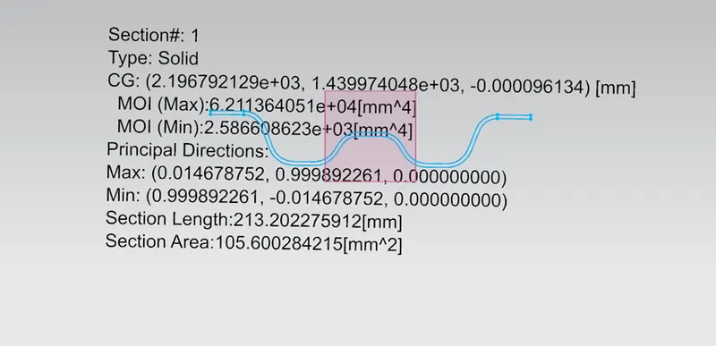
Moment of inertia: I =2586.608mm^4
So here the design is satisfied for both heat distortion and snow load there is no emboss needed because the components can withstand the strength.
Draft Analysis:
- Enables to detect whether the part you drafted will be easily removed after being manufactured.
- The Draft Analysis command enables you to detect if the part you drafted will be easily removed.
- This type of analysis is performed based on color ranges identifying zones on the analyzed element where the deviation from the draft direction at any point, corresponds to specified values.
- The part is analysed by keeping 5degree limit angle.
Roof analysis:
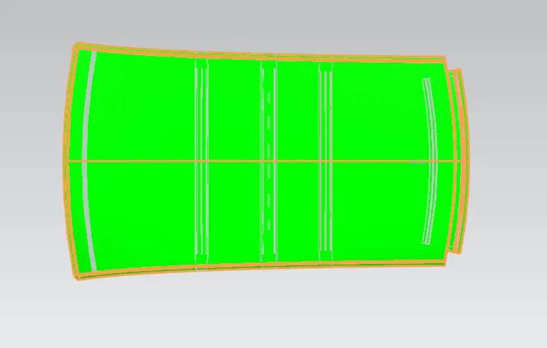
Bow roof 1 analysis:
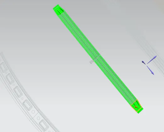
Bow roof 2 analysis:
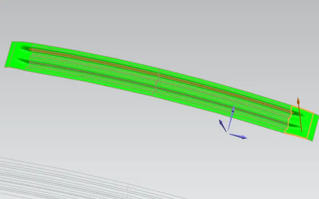
Rear roof rail :
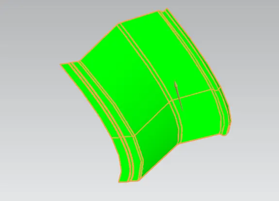
Front roof analysis:
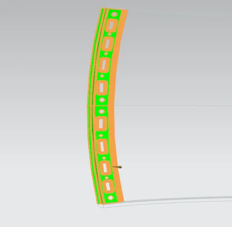
Centre roof analysis:
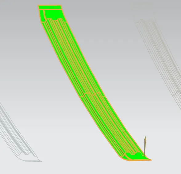
Conclusion:
- The roof design is made as per standards given in the mastic design
- Calculate whether it will satisfy the heat distortion criteria and snow load conditions
- It also tells how to provide the strength to the structure so that it can withstand against deformation during roll over.