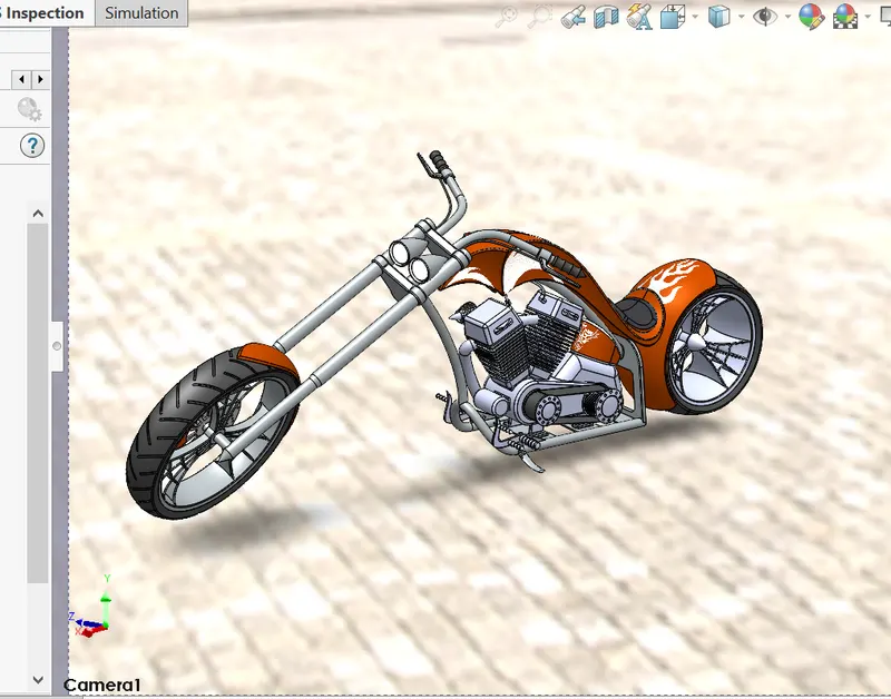
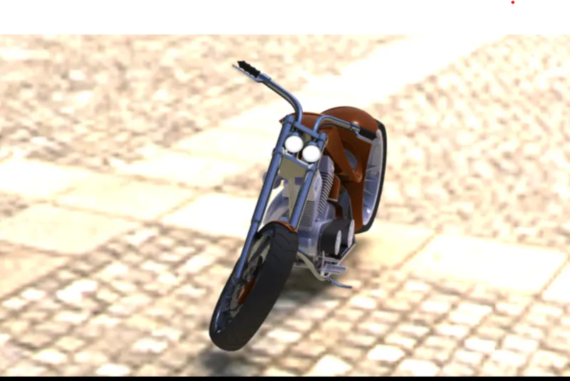
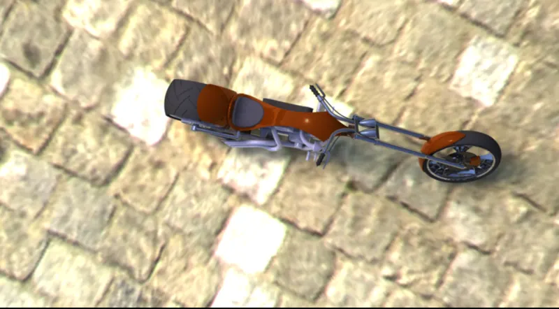
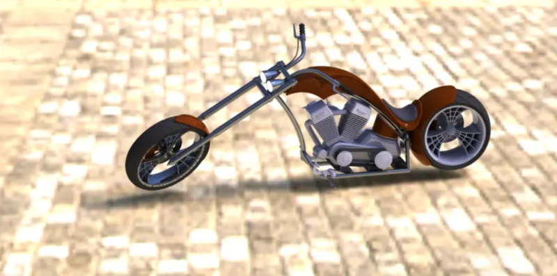
Photo Realistic Rendering
PROJECT REPORT
ON
MODELING OF AMERICAN CHOPPER USING SOLIDWORKS
From- Princy A Pereira
INTRODUCTION
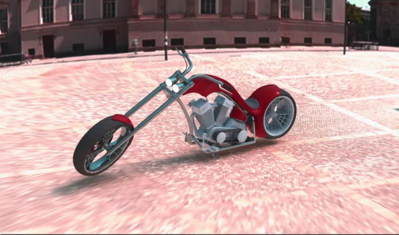
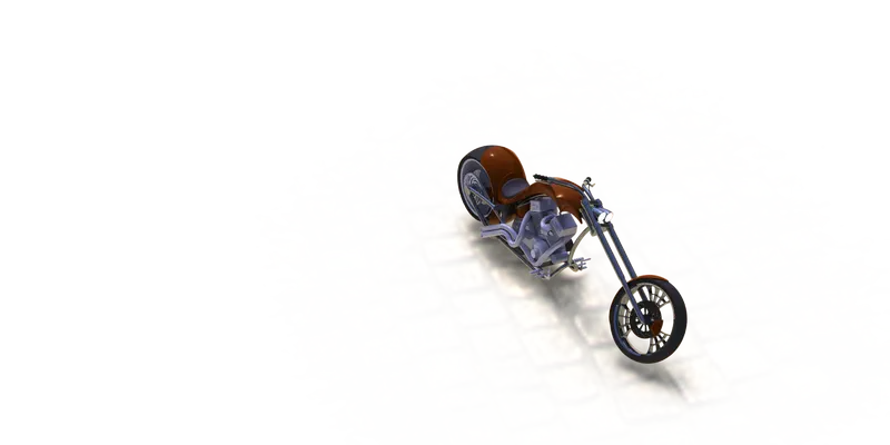
This project explains on the designing of the chopper its different parts and assembly from which we get a complete design of a chopper model using Solidworks. Later on we also get to know about the rendering using Solidwork Visualize standard or using the Photoview 360 in which we add decals , appearance and scene to assemble a complete environment of a chopper to get a realistic view of the chopper.
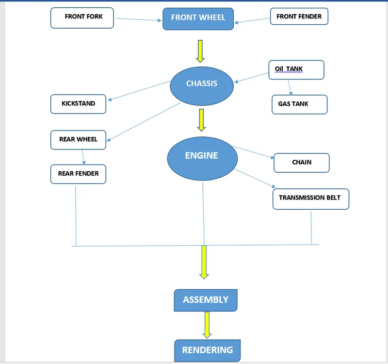
The Parts used in this models are:
- Chassis
- Transmission Belt
- Chain
- Rear and Front Fender
- Front and Rear Wheel
- Front Fork with headlights and handle grips
- Gas tank and Oil tank
- Kickstand and Foot Pedals
Design Methodology Using Flow Chart
DESIGN FEATURES USED WHILE MODELLING
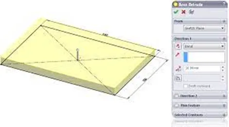
- BOSS EXTRUDE
It is a basic tool in Solidworks which converts a 2D sketch in to a 3D model with respect to its geometry in normal direction. First, we have to draw a fully closed 2D sketch and then extrude it by defining its starting point, ending point, contours and direction of extrusion.
An extrude operation can either add material to a part or remove material from a part.
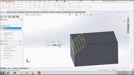
- CHAMFER:
It is used to remove a sharp edge by creating a sloped edge, vertex or face. Distance and angle of the chamfer are defined.
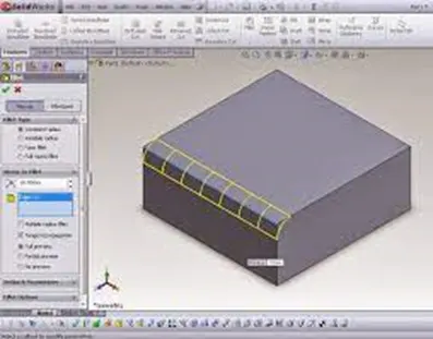
- FILLET:
They are placed features that round off or exterior corners or features of part. Face fillets between two adjacent faces or face sets. All fillets and rounds created in a single operation become a single feature.
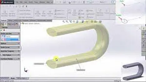
- SWEEP:
A sweep tool is used to sweep a closed 2D sketch along an open or closed path. This tool is generally used for making tubes and bars. A closed loop and a path to sweep are required.
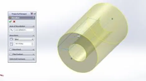
- REVOLVE:
The revolve feature is used to revolve a 2D sketch along an axis or centreline and makes it a 3D model. A 2D sketch is drawn and revolved by selecting a line as a reference for axis of rotation and defining the angle of rotation.
- SHELL:
The shell tool hollows out a part, leaves open the faces you select, and creates thin-walled features on the remaining faces. If you do not select any face on the model, you can shell a solid part, creating a closed, hollow model. You can also shell a model using multiple thicknesses. The thickness of the shell is defined.
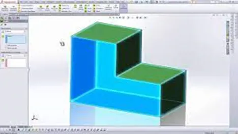
- KNIT SURFACE:
It is used to combine 2 or more faces and surfaces into one.
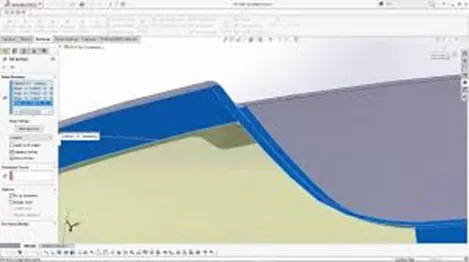
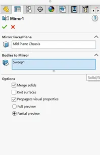
- MIRROR:
Mirror tool in solidworks is used to copy a 2D or 3D object about a reference line or plane. We can have either only the mirrored object or both the original and mirrored object.
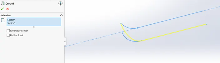
- PROJECTED CURVES:
A projected curve is a 3D curve that represents the intersection of two extruded surfaces of two sketches on intersecting planes.
- LINEAR & CIRCULAR PATTERN:
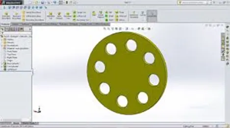
The Linear Pattern Command is used to drive features, faces, or bodies in a linear direction. The Circular Pattern Command is an excellent tool used to replicate features, faces, or bodies in a rotational manner about an axis.
- MATES:
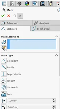
Mate operation is the basic tool for assembling the parts. There are various mate operations such as coincident, parallel, perpendicular, tangent, concentric, lock, etc. We can mate two faces by defining distance or angle between them.
MODELLING
- TRANSMISSION BELT:
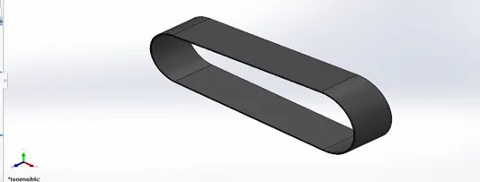
Belts may be used as a source of motion, to transmit power efficiently or to track relative movement. It was modelled by using basic tools like extrude and fillets. Finally, appearance was given to the belt.
- FRONT AND REAR FENDER
A Fender is the part of a car, truck or motorcycle that surrounds the wheel well. The primary function of a Fender is to prevent dirt and debris from being thrown into the air by the tire. It was very easy to model these fenders. Both fenders are modelled by using features like revolve, split and other features with different dimensions.
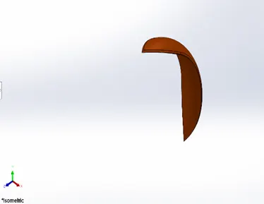
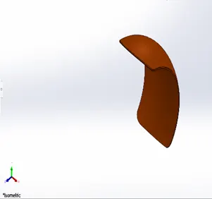
Front Fender Rear Fender
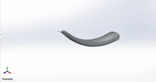
- KICKSTAND
A kickstand is a device that allows the bike to be kept upright without leaning against another object or the aid of a person. A kickstand is usually a piece of metal that flips down from the frame and makes contact with the ground.
- FRONT AND REAR WHEEL
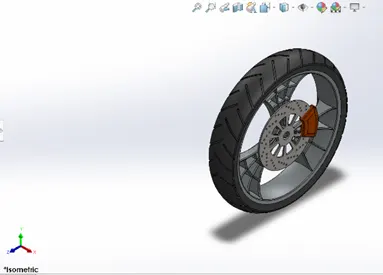
The front tire experiences the greatest forces during braking. First, the rim was created using revolve feature and spider webbed spokes were created by using arcs and offsets. Then rotor and caliper were modelled. Finally the tire was modelled using revolve and treads were applied.
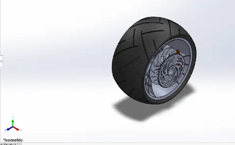
The rear tire is primarily used for acceleration and propelling the motorcycle forward. It is wider than the front wheel to improve stability of the bike. The steps followed for front wheel were used here. But this wheel has a rear sprocket as additional component. It has varying dimensions.
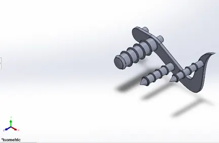
- PEDAL:
A pedal is a strong rigid body and used to rest the foot while riding bikes. Splines, fillets, dome and linear pattern were some of the features used to model the pedal.
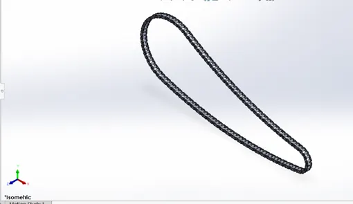
- CHAIN:
Chain is used to transmit mechanical power from engine to rear wheel. Roller chain is the commonly used type. Though the chain is a complicated model, it was easily modelled by using mirror, curves and curve driven pattern. The links were modelled as blocks and later imported. The curve driven pattern was done multiple times to get the accurate result.
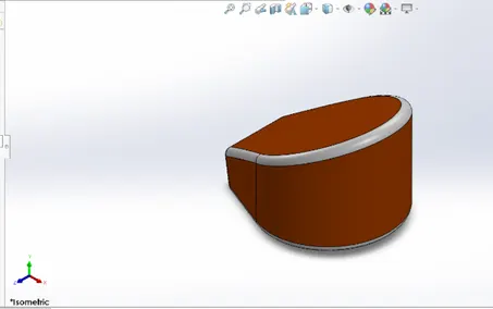
- OIL TANK:
Whether it is a car or a bike, a vehicle's engine is dependent on the fuel tank for continuous fuel supply. In the future, it may be replaced by batteries in electric vehicles. Oil tank was modelled by using dynamic mirror entity and combine features. Shell feature was used to make it hollow. It was a simple model.
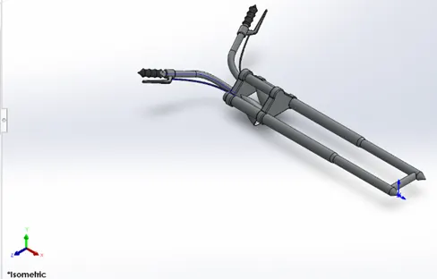
- FRONT FORK:
A front fork connects a motorcycle's front wheel and axle to its frame, typically via triple clamps. Most forks incorporate the front suspension and front brake, and allow the front wheel to rotate about the steering axis so that the bike may be steered. This was modelled by using features like extrude and mirror. Projected curves were used to model the handles and cables.
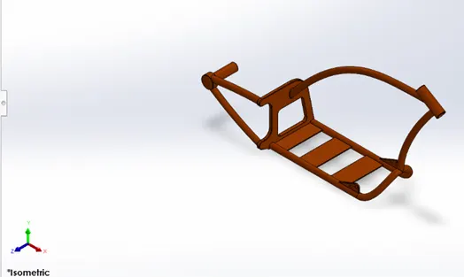
- CHASSIS:
Chassis is the main body of the chopper. It is the skeletal frame of the bike and holds other components like front fork, pedals, kickstand, oil tank, gas tank and engine. It provides strength and support to the bike.
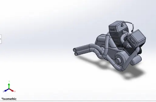
- ENGINE:
Engine is the heart of bike. It provides the power necessary to drive the vehicle. A picture is imported for reference before modelling. First, bottom part of the engine, consisting of crank shaft, motor and transmission pulleys, was modelled. Then upper part of the engine with cooling fins are drawn. Then rear sprocket and air filter were modelled. Finally the exhaust system and spark plug were modelled using splines, projected curves and sweep features.
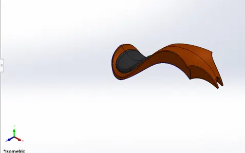
- GAS TANK:
The gas tank covers the oil tank and engine and also acts as a shield that prevents the heat from engine. The seat and opening for fuel tank are located on the top of gas tank. This also involved using a reference picture for sketching. One half of the tank was created and the mirrored. Then seat was modelled on the top of it and fillets were applied.
ASSEMBLY OF THE CHOPPER
In assembly, we use mate feature to locate and relate the parts with one another. Initially Chassis was inserted and fixed. Then other components were inserted and related to the chassis. Some parts were modified during assembly to make it perfect.
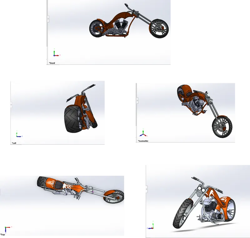
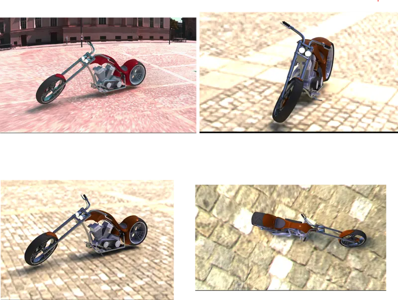
RENDERING OF THE CHOPPER
- In rendering, the chopper was made to set up in such a way to look natural and realistic.
- Decals were added to the body parts such as Gas tank, Rear Fender and Oil tank.
- Scene is added to the model by giving the background view.
- Using solidworks visualize, the appearances, background scenes and camera views were changed.
- Or we can also use Photoview 360 to change the appearance, color of the chopper and the scene composition
- Then final rendering was done to make the ch
CONCLUSION
- In this project we learnt how to design the part models in solidworks software.
- We got a clear idea on how the features are used to get an appropriate 3d model.
- Later we got to know on the assembling of all the part design and designing a good chopper.
- We also got to know how to use rendering on the chopper to give us a natural and realistic view using Solidworks Visualize standard software or by using Photoview 360 to get a proper, a cool and realistic one.