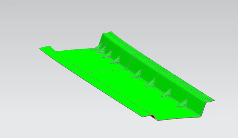
Roof challenge
OBJECTIVE:
- The Objective of this project is to design car roof with essential flanges and reinforcement like ditch area, front roof rail, bow roofs, central roof rail and rear roof rail for the given styling surface.
- Perform the calculation for the heat distortion and snow load criteria to determine whether the bow roofs are at the correct positions.
- Finding moment of inertia and section modulus for bow roof rails.
- Perform the draft analysis for each reinforcement.
INTRODUCTION:
An automobile roof or car top is the position of an automobile that sits above the passenger’s compartment, protecting the vehicle occupants from sun, wind, rain, and other external elements, Roof is the structure above the wind shield glass having the reinforcements to provide the strength to the overall structure.
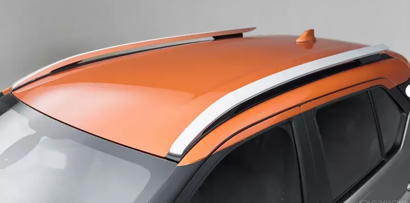
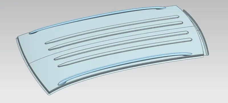
REINFORCE A CAR ROOF
If the roof is flat, it is very weak and cannot able to with stand the forces like snow, so in order to increase the strength of the roof these reinforcements like front roof rail, centre roof rail, rear roof rail, and the bow roofs are introduced and joined to the flat surface of the roof with the different joining process.
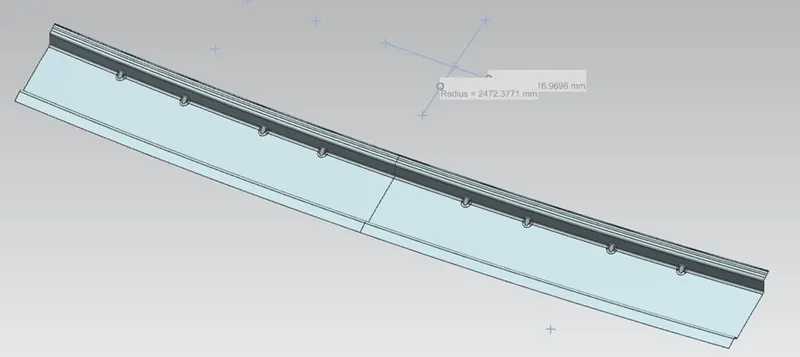
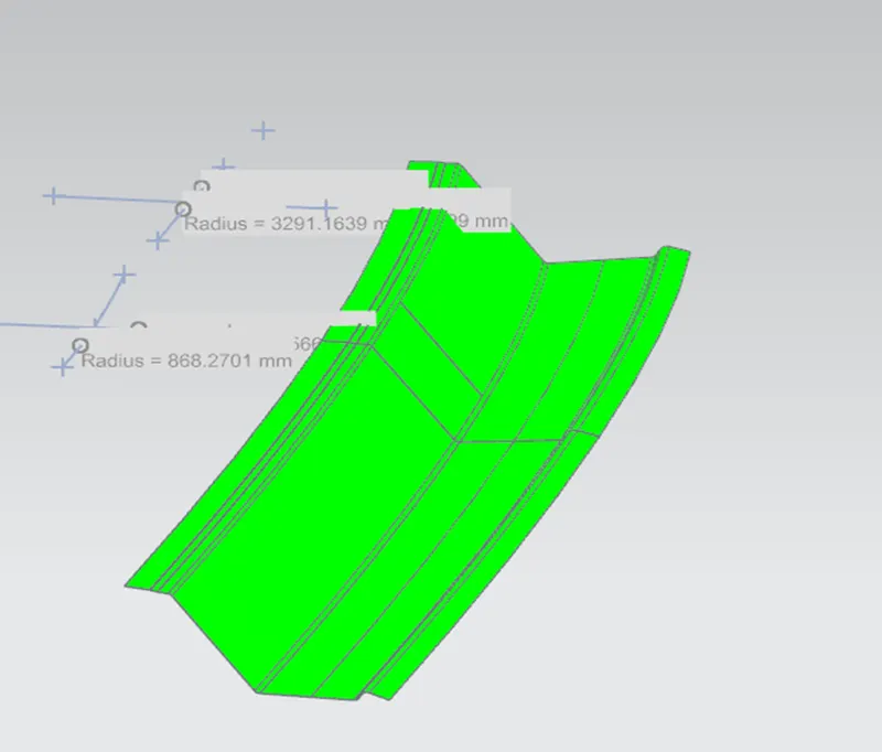
FRONT ROOF RAIL:
Front roof rail is the one which joins the wind shield glass, body side outer and the inner panel also. Here the front roof rail is designed based up on the master section given.
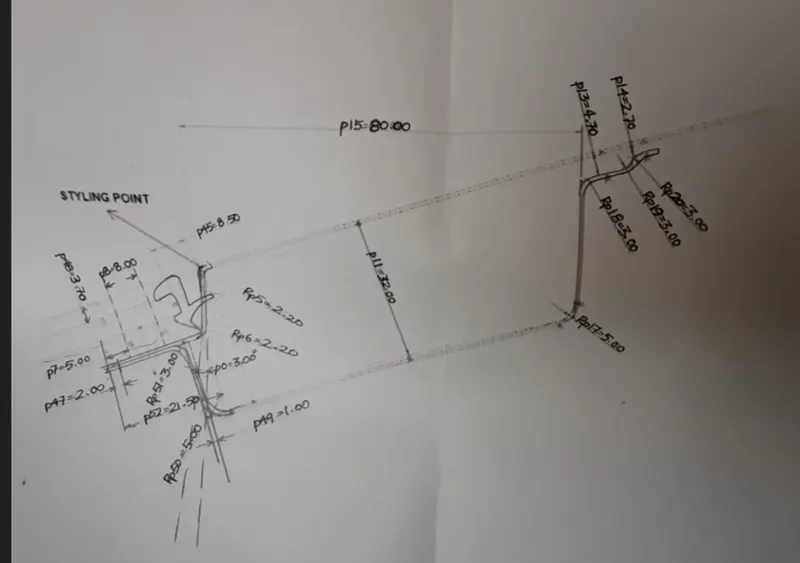
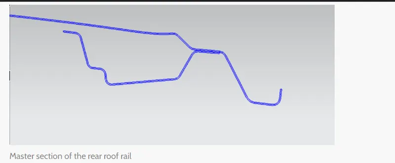
REAR ROOF RAIL
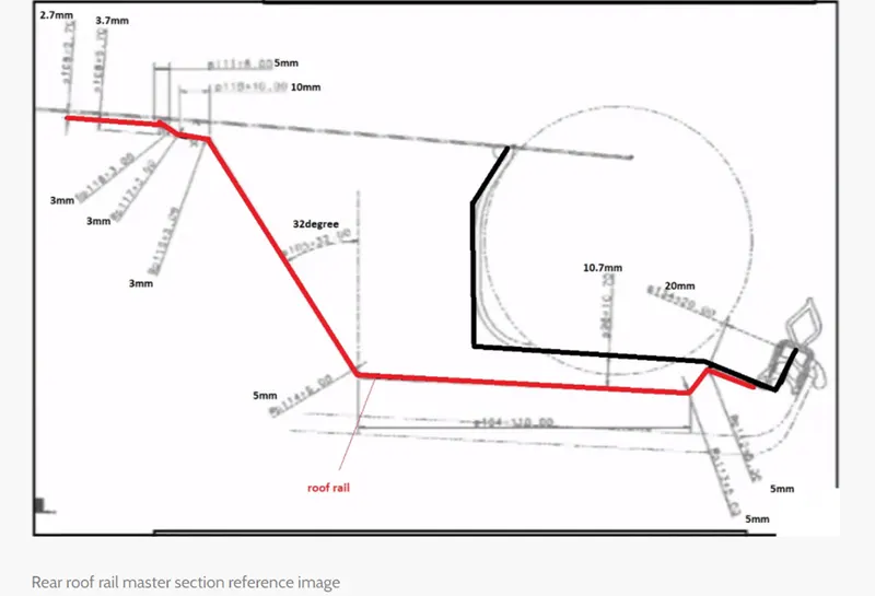
Rear roof rail is the one which joins the back door and the body side outer.
BOW ROOF:
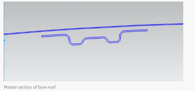
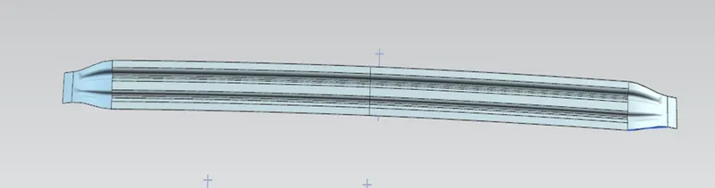
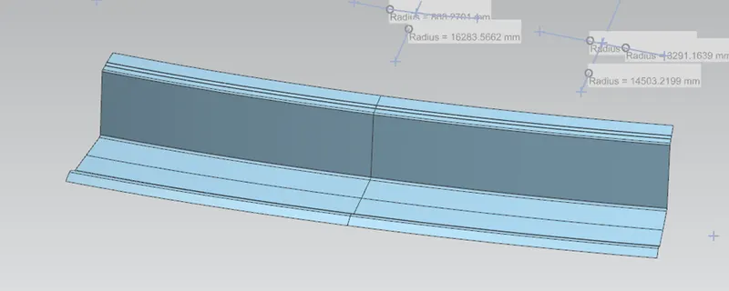
The bow roofs are given to improve the torsional stiffness and load bearing capacity of the roof structure. The number of bow roof present is depending on the overall size of the roof.
Here 2 bow roof and one centre reinforcement are implemented.
- First bow roof
- Centre reinforcement
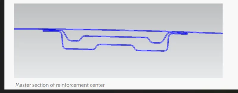
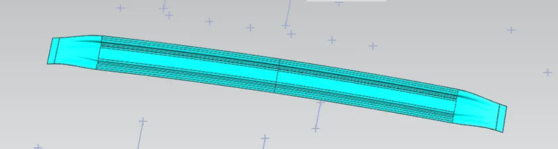
- 2nd bow roof
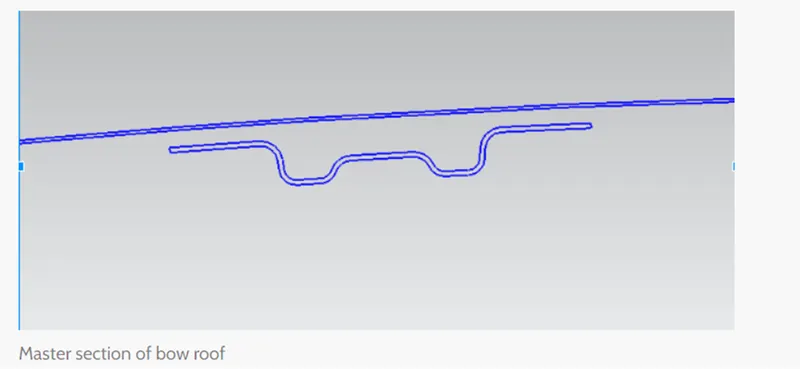
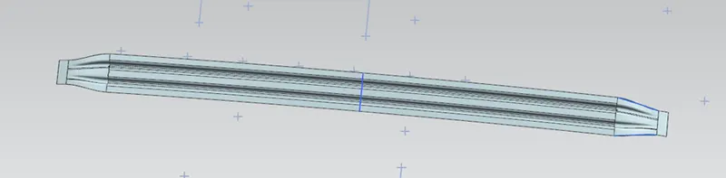
- Rear roof Rail
Joining Process:
Mastics are introduced b/w the roof outer panel and the reinforcements for joining where ever the mastic are introduced there is remarkable improve of the strength.
Spot welding is also introduced to join the reinforcement and the outer panel.
STYLING SURFACE TO EXTRACTED SURFACE:
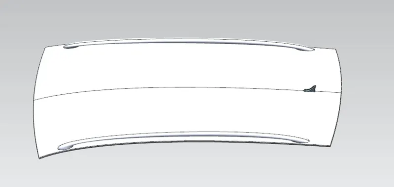
The styling team has provided the solid outer panel from that we are extracting the surface to model the necessary reinforcements like Ditch area, Front Roof Rail, Bow Roof Rails and Rear Roof Rail.
Design consideration for a roof:
- Visibility criteria
- Head clearance
- Curvature study
- Heat Distortion and snow load criteria
- Draft analysis
BOW ROOF RAIL CALCULATION:
HEAT DISTORTION CALCULATIONS
Heat distortion temperature is the temperature at which the metal softens and deforms under a specific load. This study is done to check the ability of the roof to withstand high temperature with respect to the positioning of the reinforcements which contribute to increased strength.
W = [1.73 x 10^(-3) x L] + [1.85 x 10^ (-8) x (R^2)/t] + [ 1.10x10^(-3) x l] - 2.68
Judgement Condition: OK< 2.7> 3.1
Were
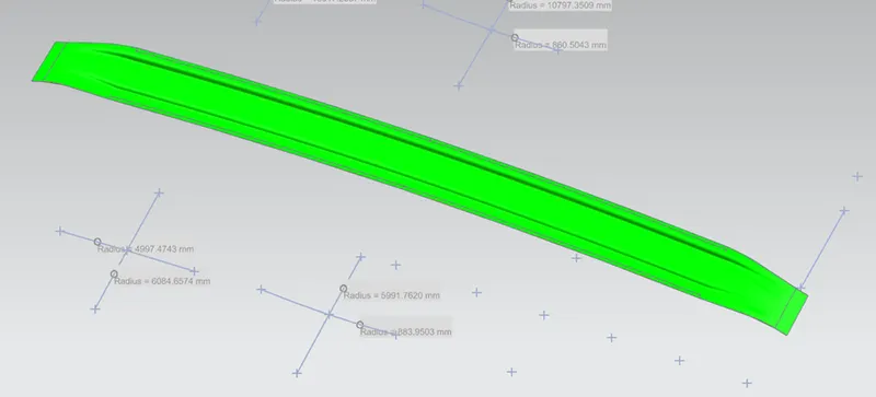
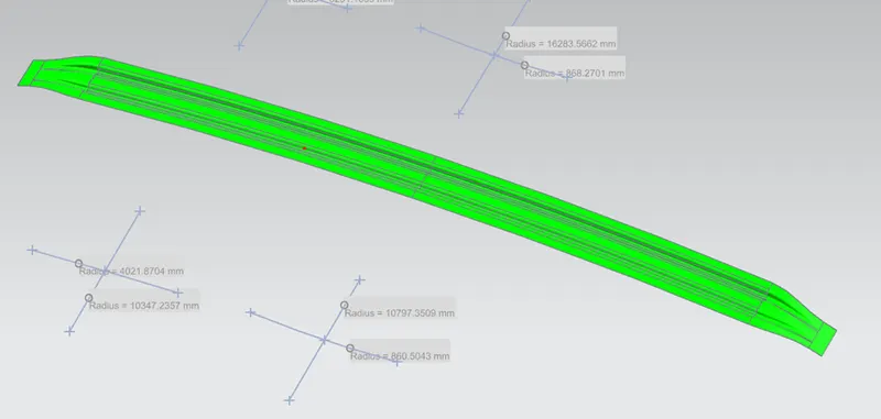
L = Roof Length in X-Direction[mm] (Roof dimension in 0-Y)
R = Roof curvature
R = 2(Rx*Ry)/(Rx+Ry)
Rx = X curvature
Ry = Y curvature
t = Roof plate thickness [mm]
l = Bow Roof Span [mm]
PROCEDURE TO MEASURE THE PARAMETERS:
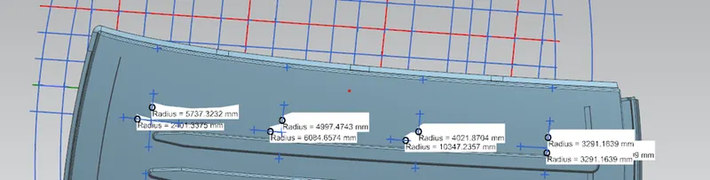
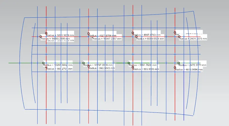
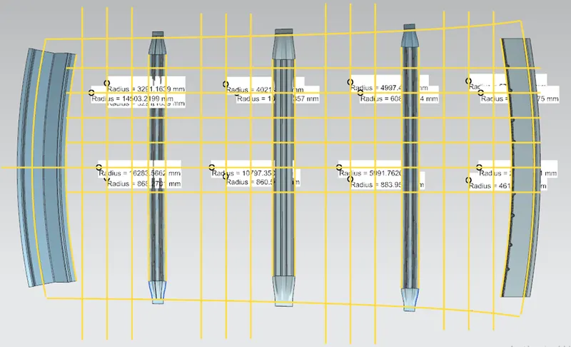
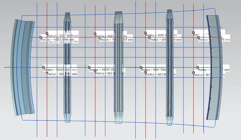
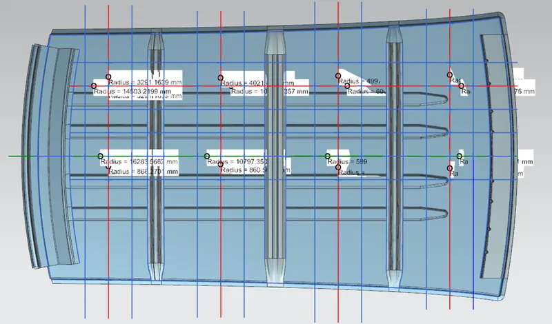
- On Plane parallel to the top plane draw sketch in which OY line is offset by 300mm.
- Draw lines perpendicular to OY line passing through point exact midpoint of the two adjacent parts (e.g., midpoint between front rail and bow roof 1)
- Offset these reference line on both side by 100mm
- Mark intersection points of reference line and 100mm offset lines.
- These reference points are then projected on to roof outer panel surface to create curves.
- Take all necessary measurements required to calculate W value as per mentioned formula.
|
S.NO. |
BOWs |
Rx |
Ry |
R |
I |
L |
t |
(R^2)/t |
W |
OK/NG |
|
1 |
FR & 1st |
2401.3375 |
5737.3232 |
3385.63059 |
371.6898 |
1469.8186 |
0.75 |
1.528x 10^7 |
0.553458 |
OK |
|
2 |
1st & CTR |
6084.6574 |
4997.4743 |
5487.7385 |
430.6990 |
1469.8186 |
0.75 |
4.015369x 10^7 |
1.07776 |
OK |
|
3 |
CTR & 2nd |
10347.2357 |
4021.8704 |
5792.3213 |
430.6527 |
1469.8186 |
0.75 |
4.4734648x 10^7 |
1.163 |
OK |
|
4 |
2nd & RR |
3277.8519 |
14590.7497 |
5353.1123 |
332.9208 |
1469.8186 |
0.75 |
2.149185x 10^7 |
0.62571 |
OK |
HERE WE SEE THAT THE ROOF IS COMPLETELY SATISFYING THE CONDITION OF HEAT DISTORTION.
SNOW LOAD PREDICTION FORMULA:
Snow load is the downward force on a cars roof by the weight of accumulated snow and ice. The roof can fail if the snow load exceeds the weight the roof was designed to shoulder or if the roof was poorly designed or constructed.
So, there is a formula to predict the strength of the roof.
Qr = [Iy x t2] / [α x s x [(Rx + Ry)/2]2 x 10-8]
Note: The Qr value given over here is correct. There was a typo error in the formula given in the video.
Where
α = My x Lx2 x 10-12, My = Y(Ly-Y)
Judgement condition = Qr ≥ 3.1
250 ≤ s ≤ 380
t = Roof plate thickness [mm]
Ly = Distance between the front and rear roof Rails on the Vehicle along with 0Y[mm]
Length of Roof panel with the centre point between Roof rail Front /Rear as the front and rear reference point.
Lx = Distance between the Left and Right end of the roof on the Roof BOW [mm]
Width of the roof panel exposed on the surface.
Y = Distance front Roof Rail to Roof BOW[mm]
s = Distance for which Roof BOW bears divided load [mm]
s = L1/2 + L2/2
Iy = Geometrical moment of inertia of Roof BOW (Y cross-section) [mm4]
Rx = Lateral direction curvature radius of roof panel Y cross-section on Roof BOW [mm]
Roof panel curvature Radius of the Length Lx in Front view
Ry = Longitudinal Direction curvature radius of the Roof panel X cross-section on Roof BOW [mm]
Roof panel X curvature radius of length s in Side view
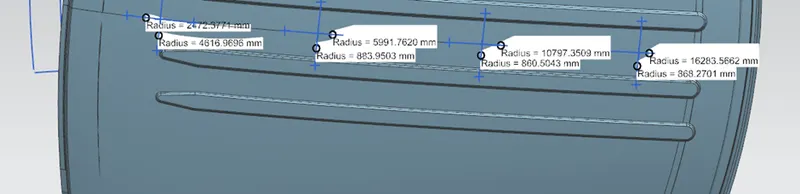
|
S.NO |
BOWs |
ly |
α |
Lx |
Ly |
y |
L1 |
L2 |
s |
RX |
Ry |
t |
Qr |
Determination (Qr) |
|
1 |
FR & 1st |
592.4049 |
0.972 |
743.3796 |
1469.8186 |
435 |
435 |
511 |
256.3864 |
4616.9696 |
2472.3771 |
0.75 |
0.0427 |
NG |
|
2 |
1st & CTR |
385.541 |
1.0584 |
861.398 |
1469.8186 |
511 |
511 |
511 |
256.5 |
883.9503 |
5991.7620 |
0.75 |
0.02491 |
NG |
|
3 |
CTR & 2nd |
668.1499 |
1.058 |
861.3054 |
1469.8186 |
511 |
511 |
435.5 |
218.9233 |
860.5043 |
10797.3509 |
0.75 |
0.020619 |
NG |
|
4 |
2nd & RR |
0.9731 |
645.8416 |
1469.8186 |
435.5 |
435.5 |
868.2701 |
16283.5662 |
0.75 |
CONCLUSION
Here we can see that SNOW LOAD condition is not satisfied, so in order to strengthen the roof at these are emboss are created on outer roof.
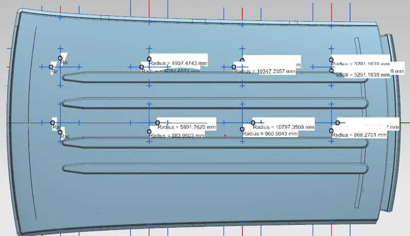
EMBOSS TO STRENGTHEN THE ROOF
SECTION MODULUS STUDY OF THE ROOF RAILS:
The section modulus of the cross-section shape is of significant importance in designing of structure. It is a direct measure of the strength of the structure, bending resistance.
Section modulus (S) = l/Y
Were
I= Moment of inertia (mm4)
Y=Distance between the neutral axis and the extreme end of the object (mm)
BOW ROOF RAIL 1:
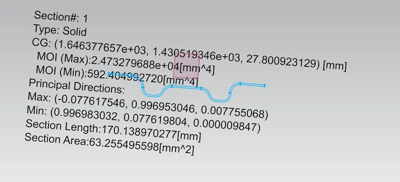
INERTIA ANALYSIS
I=592.40499 mm4
Y=70/2= 35 mm
S= I/Y = 592.40499/35 = 16.9258 mm3
CENTRE REINFORCEMENT BOW ROOF:
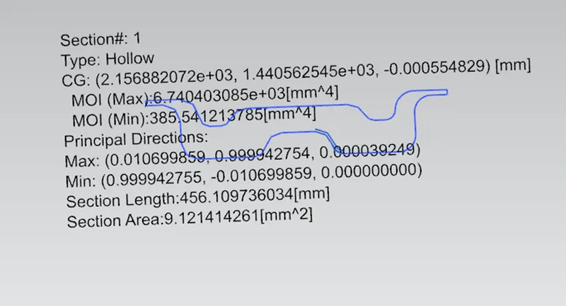
INERTIA ANALYSIS
I=385.54121 mm4
Y=90/2= 45 mm
S= I/Y = 8.5675 mm3
BOW ROOF RAIL 2:
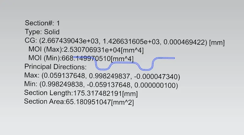
INERTIA ANALYSIS:
I= 668.1499 mm4
Y=70/2 = 35 mm
S= I/Y = 19.0899 mm3
DRAFT ANALYSIS
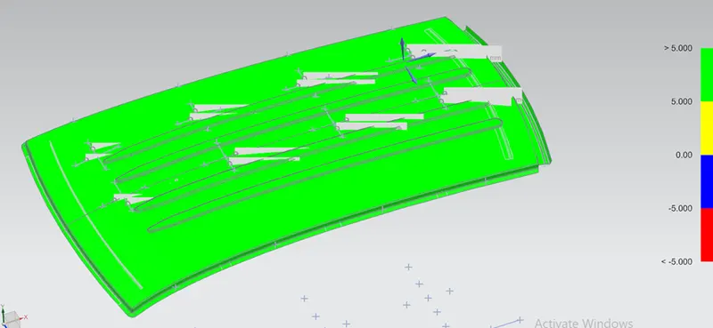
In NX to check whether the sheet metal part we have designed can be deep drawn, there is an option called draft analysis. This type of analysis is performed based on colour ranges identifying zones on the analysed element where the deviation from the draft direction at any point, corresponds to specified values.
ROOF
FIRST BOW ROOF
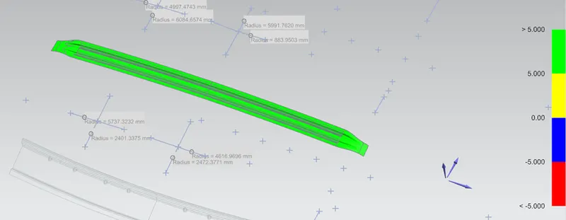
CENTRE REINFORCEMENT ROOF
UPPER BOW:
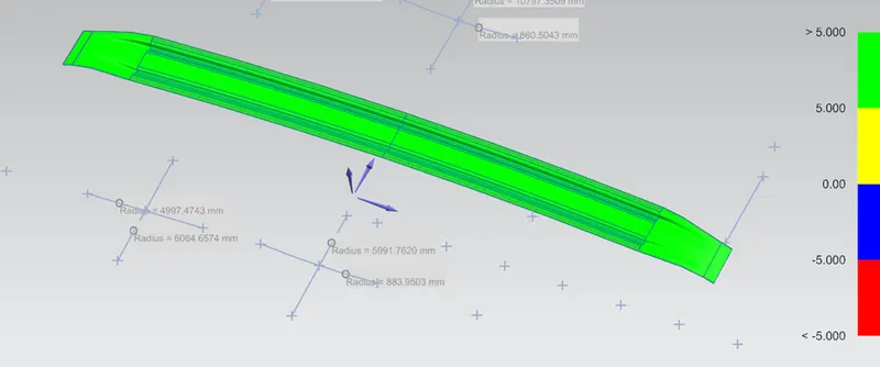
LOWER BOW:
SECOND BOW ROOF
REAR ROOF
Front roof rail