Roof challenge
Automobile Roof Design
Introduction
Roof is basically a cover that is mounted over the passenger’s head which prevents passengers from any external conditions. The roof design plays a crucial role in providing strength to the car. The roof designs vary from model to model, there are many roof types such as Sun roofs, Hard tops, T tops, convertible’s etc....
Design Methodology
- Importing and analysing the Masters sections from the styling team.
- Creating the surfaces and Ditch area (Roof outer panel) for the roof.
- Offsetting the surfaces and Designing Front roof rail using NX cad.
- Designing Rear Roof rail using NX cad.
- Designing of required number of bow roof rails to increase strength.
- Designing Centre roof rail to increase the strength of the roof.
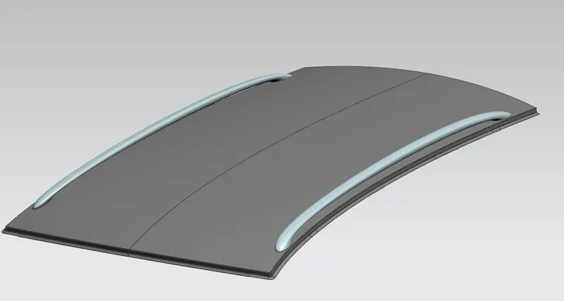
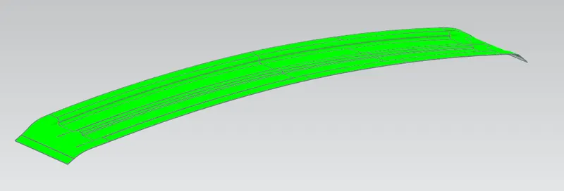
Design of Roof outer Panel ( Ditch area)
- Designing the ditch area of the roof requires many considerations from various parts of the car, like the Wind shield clearance, back door clearance, Visibility clearance.
- The Ditch area must have a required draft provided by the styling team a required draft which is 3 degree in present case.
- Reinforcements will be attached to the outer panel and ditch area by spot welding or by mastic sealing.
- The Ditch are is then connected to the surrounding parts and gets fixed to the car.
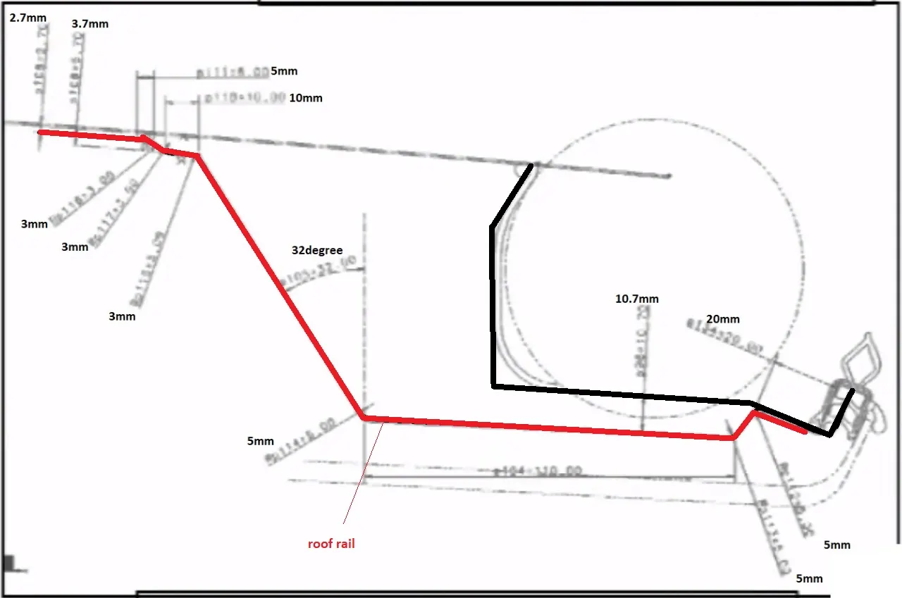
Front roof rail
- The Front roof rails will be connected to the wind shield of the car and also connected to the ditch area of the Roof outer panel.
- The Front roof rail must be designed at certain draft so that the reinforcement does not disrupt the visibility area.
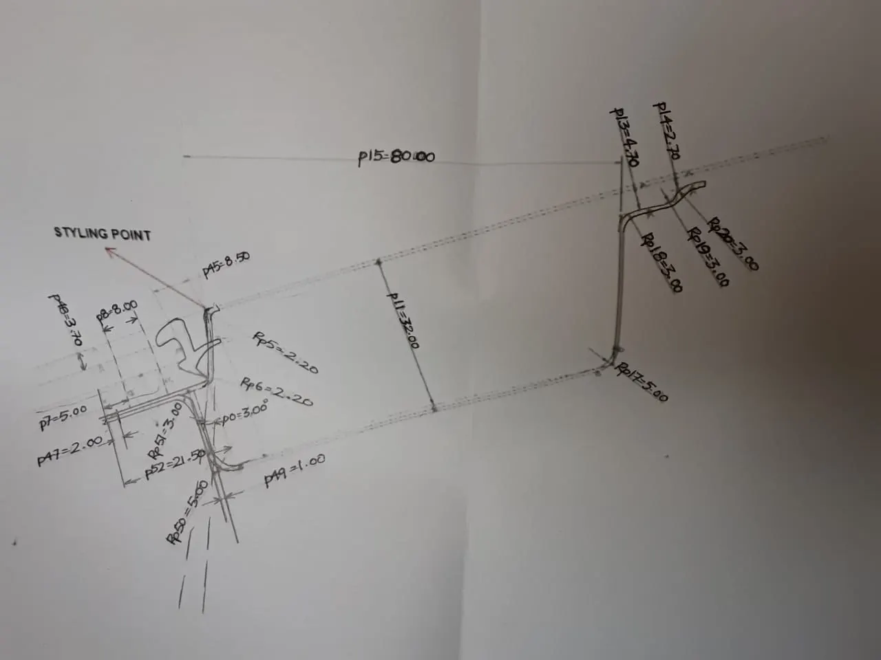
- The front roof rail is designed in Nx Cad by using the master section provided by the styling team.
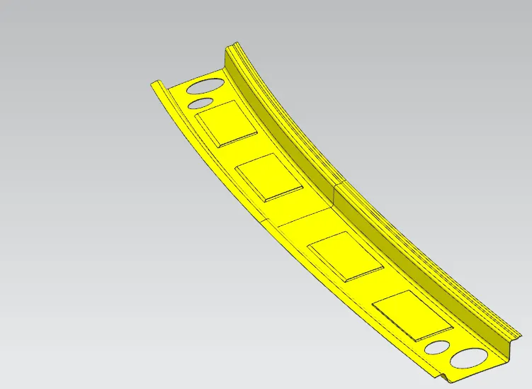
- The front roof rail has also been provided with Cuts and embosses so that the strength and stress destitution properties increases.
Master Section
3D Cad Design
Rear roof rail
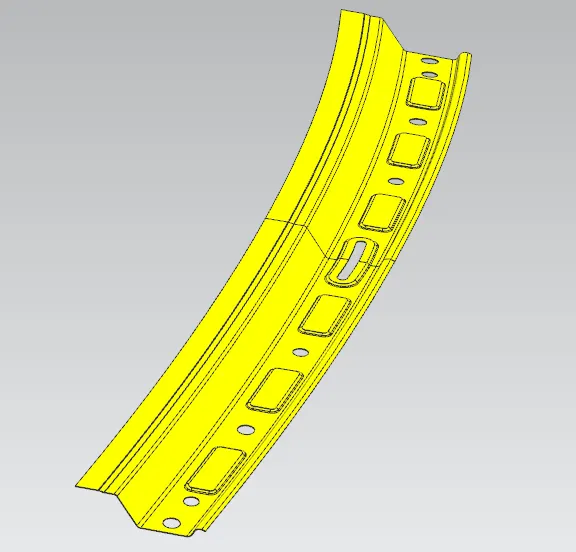
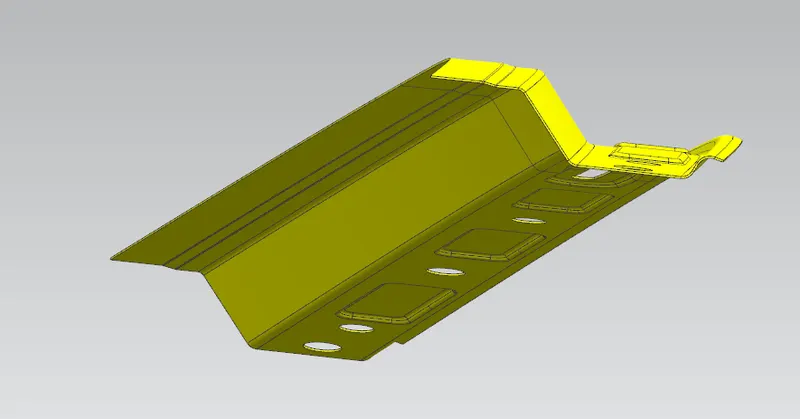
- The Rear roof rail will be attached to the ditch area of the roof and back door area of the car
- The rear roof rail must be designed according to required drafts considering the axis rotational path of the back door hinge.
- The rear roof rail must increase the strength of the car and also sustain the continues usage of back door.
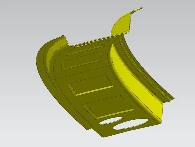
- To sustain more load and have good stress distribution many embosses and cuts have been provide to the rear roof rail.
Master Section
3D Cad Design
Centre roof rail
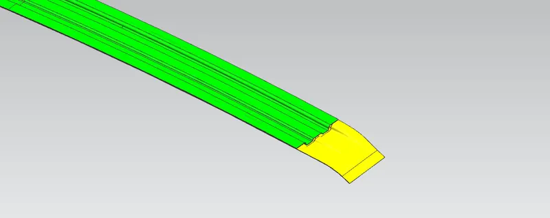
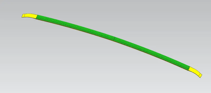
- The centre roof rail place at the centre or somewhere near the centre of the roof which provides a immense strength to the curvature of the roof.
- It provide great strength to the roof because of it position and shape.
- It will be attached to the roof by mastic sealants which takes a great amount of load and distribute all over the rail.
Bow Roof rails
- Bow roofs work on the same principle of Centre roof rail that provides stiffness to the roof curvature.
- Bow roof rails are positioned between CRR & FRR, CRR & RRR.
- They are attached to the roof surface by mastic sealants to absorb loads.
- CRR & BRR's must ensure the head room clearance to endure comfort to the passengers in the car.
- All the bow roof rails are of similar design and shape.
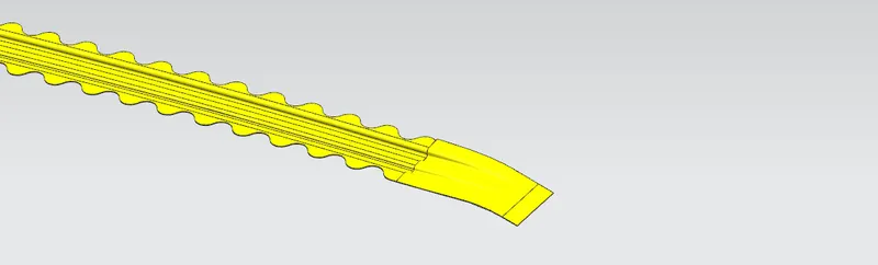
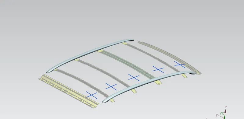
Total Roof and reinforcements assemble looks like
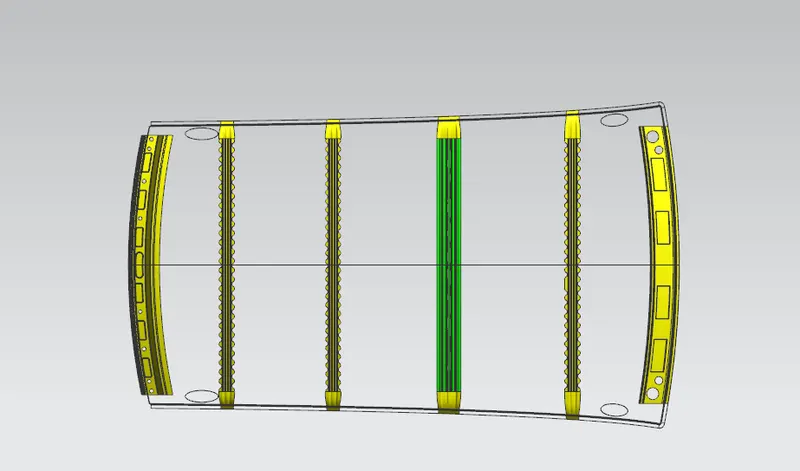
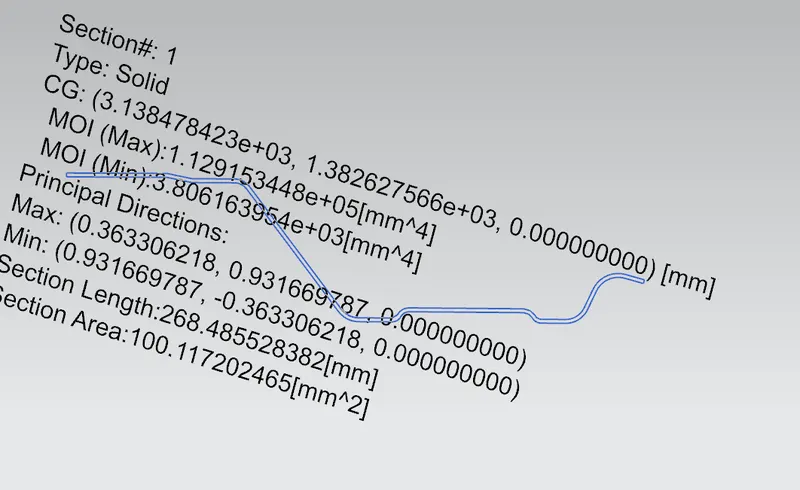
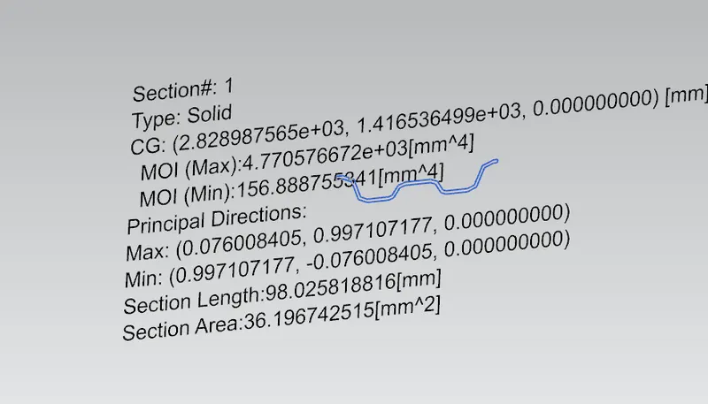
Section Inertia For the Reinforcements along 0-Y axis
Front roof rail
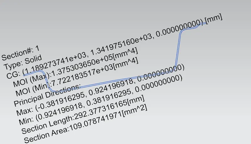
Rear roof rail
Centre roof rail
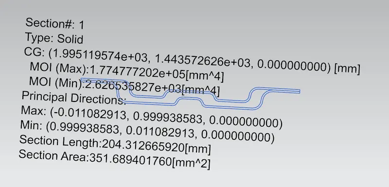
Bow roof 1
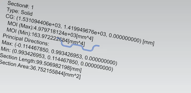
Bow roof 2
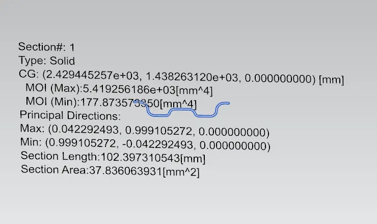
Bow rof 3
Roof Prediction Study
Predicting the Roof sustainability and defelction, stress absorbing ability can done by
- Bow Roof analysis
- Snow load Analysis
Bow Roof Prediction Analysis
- This analysis will be done at 300 mm side ways from the 0y direction which be tested in crash testing scenario.
- The roof ned to sutain the test to pass and get clearance from the design and analysis team.
W = [1.73 x 10^(-3) x L] + [1.85 x 10^(-8) x (R^2)/t] + [ 1.10x10^(-3) x l] - 2.68
Judgement Condition : OK (2.7>W>3.1)
Where
L = Roof Length in X-Direction[mm](Roof dimension in 0-Y)
R = Roof curvature
R = 2(Rx*Ry)/(Rx+Ry)
Rx = X curvature
Ry = Y curvature
t = Roof plate thickness [mm]
l = Bow Roof Span [mm]
Values
L
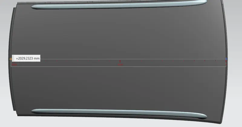
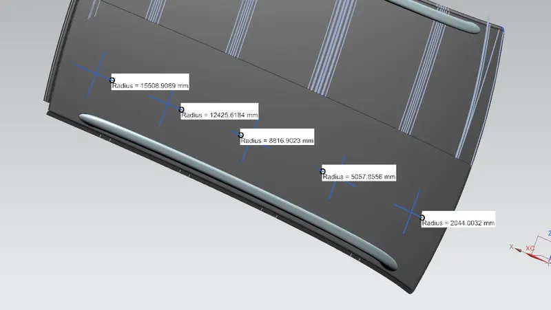
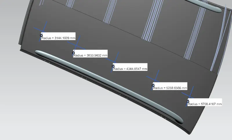
Intersection points, Rx,Ry Radius of curvatures
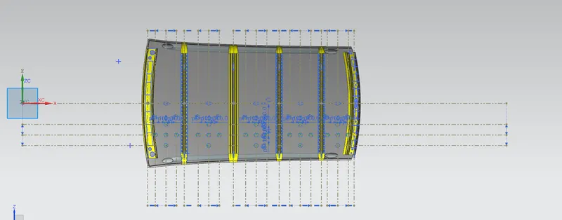
Rx
Ry
| Region | Rx | Ry | R | L | I | t | W | Result |
| FRR - BR1 | 2044.004 | 5708.416 | 3010.163 | 2029.2323 | 276.4619 | 0.75mm | 1.398 | OK |
| BR1 - CRR | 5057.855 | 5259.656 | 5156.781 | 2029.2323 | 372.3249 | 0.75mm | 1.826 | OK |
| CRR - BR2 | 8816.902 | 4344.064 | 5820.421 | 2029.2323 | 369.1486 | 0.75mm | 2.072 | OK |
| BR2 - BR3 | 12425.618 | 3633.963 | 5623.339 | 2029.2323 | 362.6966 | 0.75mm | 2.009 | OK |
| BR3 - RRR | 15508.908 | 3144.160 | 5228.615 | 2029.2323 | 234.1536 | 0.75mm | 1.762 | OK |
The results have been satisfactory for the bow roof analysis.
Snow Load Prediction analysis
This Prediction is generally used to check wether the roof is able to sustain the snow load during the winters in the morthern countries of the globe. This Checks wether the roof could re form its self after the deformation. This prediction helps to get a clear understanding about the snow load condition before sending the design to the analysis team.
This analysis will be done at 0Y direction where the the snow load has the hieghest impact.
Qr = [Iy x t2] / [α x s x [(Rx + Ry)/2]2 x 10-8]
Where
α= My x Lx2 x 10-12 , My = Y(Ly-Y)
Judgement condition = Qr ≥ 3.1
250 ≤ s ≤ 380
t = Roof plate thickness [mm]
Ly = Distance between the front and rear roof Rails on the Vehicle along with 0Y[mm]
Length of Roof panel with the center point between Roof rail Front /Rear as the front and rear reference point.
Lx = Distance between the Left and Right end of the roof on the Roof BOW [mm]
Width of the roof panel exposed on the surface.
Y = Distance front Front Roof Rail to Roof BOW[mm]
s = Distance for which Roof BOW bears divided load [mm]
s = L1/2 + L2/2
Iy = Geometrical moment of inertia of Roof BOW (Y cross-section )[mm4]
Rx = Lateral direction curvature radius of roof panel Y cross-section on Roof BOW [mm]
Roof panel curvature Radius of the Length Lx in Front view
Ry = Longitudinal Direction curvature radius of the Roof panel X cross-section on Roof BOW [mm]
Roof panel X curvature radius of length s in Side view
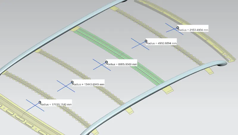
Rx
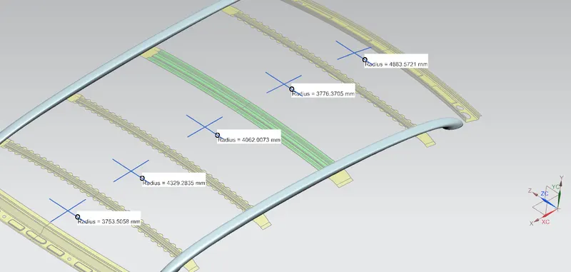
Ry
| Region | t | Iy | α | s | Rx | Ry | Qr | Result |
| FRR - BR1 | 0.75mm | 163.972 | 0.770216427 | 360.932 | 2153.490 | 4883.572 | 7.14660 | OK |
| BR1 - CRR | 0.75mm | 2626.535 | 0.876162016 | 384.824 | 4960.989 | 3776.370 | 61.5256 | OK |
| CRR - BR2 | 0.75mm | 177.873 | 0.792963841 | 372.368 | 8985.956 | 4062.007 | 2.12300 | REJECT |
| BR2 - BR3 | 0.75mm | 156.888 | 0.71807298 | 375.582 | 13443.694 | 4329.283 | 1.12040 | REJECT |
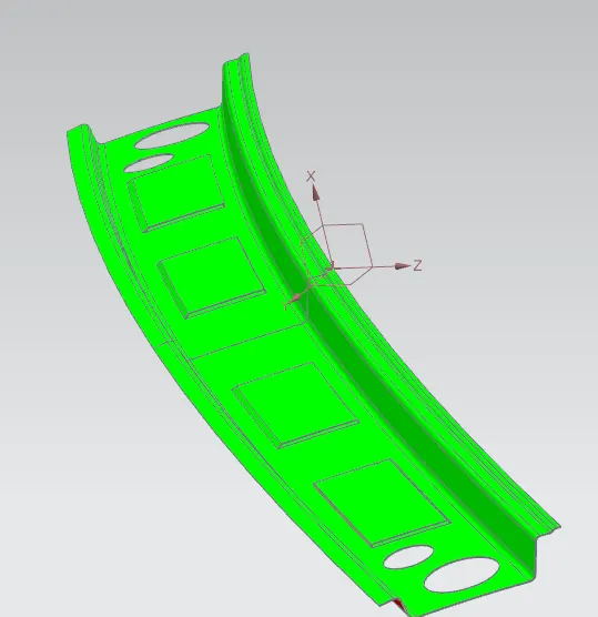
As Per the results obtained by the Snow load analysis the roof fails to sustain at BR2, BR3 so the embosses need to be added to increase the stiffness to the roof.
If embosses are not accepted then the design team should consult the styling team and ask to change the radius of curvature so that the load sutaining capacity increases.
Conclusion
The Design finally concludes that it passes the bow roof analysis and fails at two regions during the snowload analysis, where the embosses need to be added. thee embosses help the roof in sustaining more snow load and prevent it from deformation.
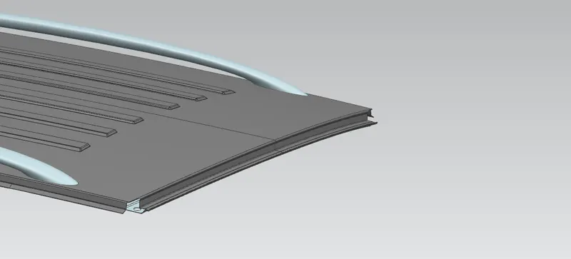
embosses like this could add stiffness and strength to the roof to sustain the loads.
Draft analysis of the reinforcements also produces good results
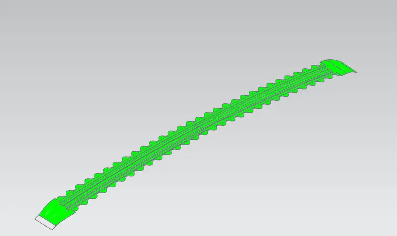
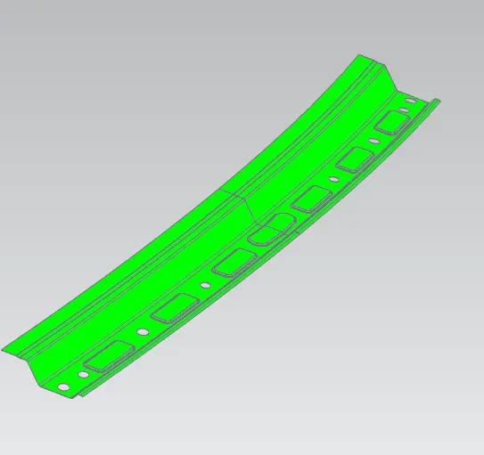
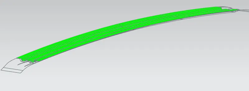
Now as the Designed is drafted and analysed by the design team, it can be sent to the analysis team for further testing and manufacturing.