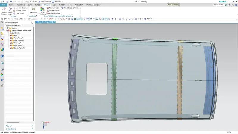
Roof challenge
Roof Challange Report
Aim:
- To develop essential flanges and reinforcements for the given styling surface.
- To conduct draft analysis
- To conduct Section Inertia Analysis on the O-Y section
- To do a curvature study on the roof and do necessary calculations
Introduction:
An automobile rood is the portion of an automobile that sits above the compartment, protecting the vehicle occupants from sun heat, rain, wind and other external factors.
Types of Roofs:
1. Convertible Roofs
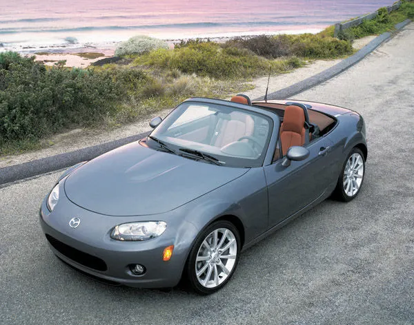
A convertible or cabriolet is a passenger car that can be driven with or without a roof in place. The methods of retracting and storing the roof vary between models. A convertible allows an open-air driving experience, with the ability to provide a roof when required.
2. Hardtops
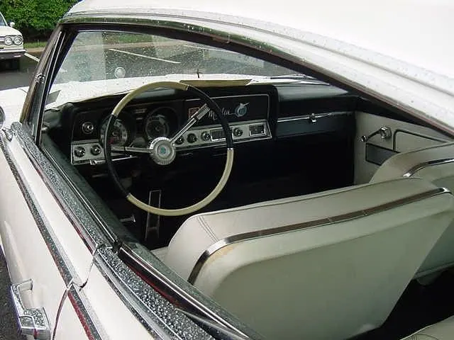
A hardtop is a rigid form of automobile roof, which for modern cars is typically constructed from metal. A hardtop roof can be either fixed, detachable for separate storing or retractable within the vehicle itself.
3. Sunroofs
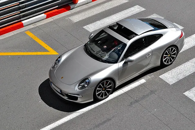
A sunroof is a movable panel that opens to uncover a window in an automobile roof, allowing light and fresh air to enter the passenger compartment. Sunroofs can be manually operated or motor driven, and are available in many shapes, sizes and styles.
4. T-tops
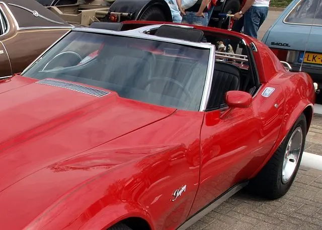
A T-top is an automobile roof with a removable panel on each side of a rigid bar running from the center of one structural bar between pillars to the center of the next structural bar.
5. Targa tops
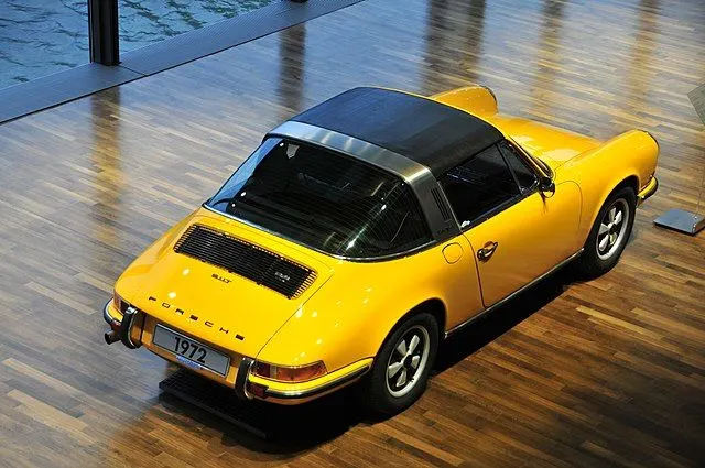
Targa top, or targa for short, is a semi-convertible car body style with a removable roof section and a full width roll bar behind the seats. The term was first used on the 1966 Porsche 911 Targa, and it remains a registered trademark of Porsche AG.
6. Vinyl Roofs
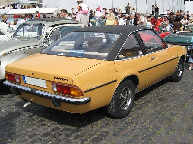
Vinyl roof refers to a vinyl covering for an automobile's top.
Creating Flanges on the Outer Surface:
1. Front and Side Flanges (Ditch Area)
From the given styling surface, the A-surface is extracted and ditch area is created considering the paramenters specified in the master section.
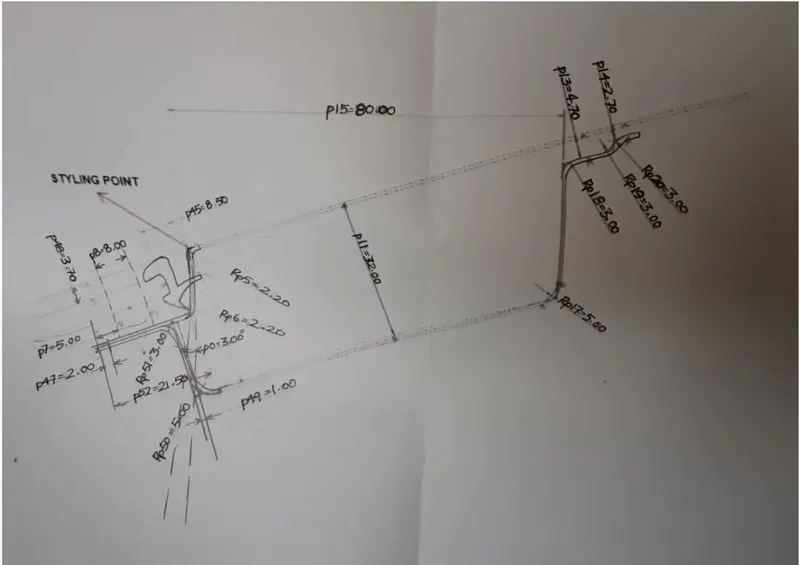
Figure: Master Section of Front Roof Rail and Ditch Area
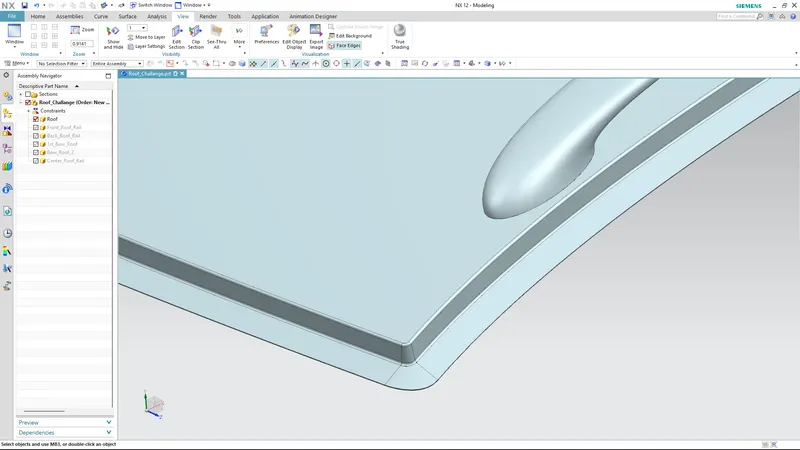
Figure: Isometric View of Front and Side Ditch Area
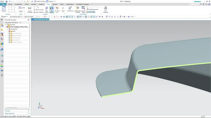
Figure: Cross-Sectional View of Front Ditch Area
2. Rear Flanges or Rear Ditch Area
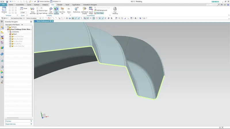
Figure: Cross-Sectoinal View of Rear Ditch Area
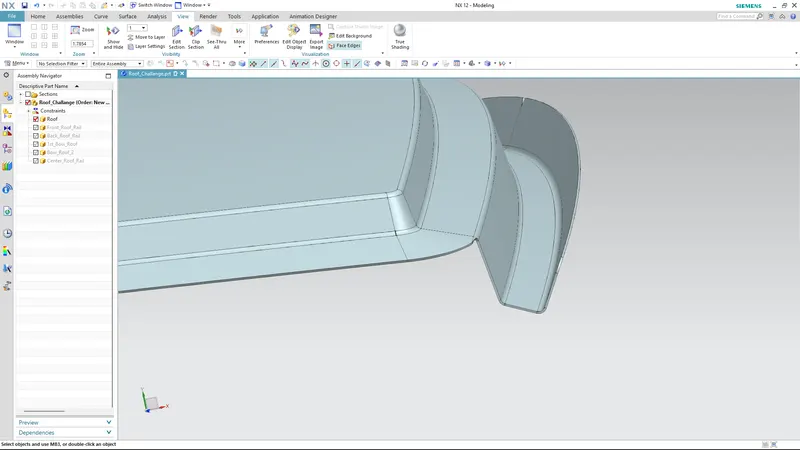
Figure: Side view of Rear Ditch Area
Roof Rails:
1. Front Roof Rail
It is the support that is joined to the windshield glass, body side outer and inner panels. Its thickness is usually 0.75 mm. The windshield end flanges are the extract offset of the roof outer surface. The bottom most flanges is decided after taking into consideration of the visibility criteria. Spot weld is applied between the front roof rail and front roof ditch area whereas mastic sealeants are applied between the other end of front roof rail and A-Surface.
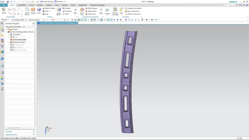
Figure: Top View of Front Roof Rail
2. Rear Roof Rail
It is the support that is joined to the back door and the body side outer and the inner panels. The thickness of this section is 0.75mm. Similar to that of front roof rail design, consideration is to be taken for the headroom clearance and the rear visibility criteria while designing the rear roof rail. Spot weld is done between the rear ditch area and one end of the rear roof flange whereas mastic sealants are applied between the other end of the rear roof rail and A-surface.
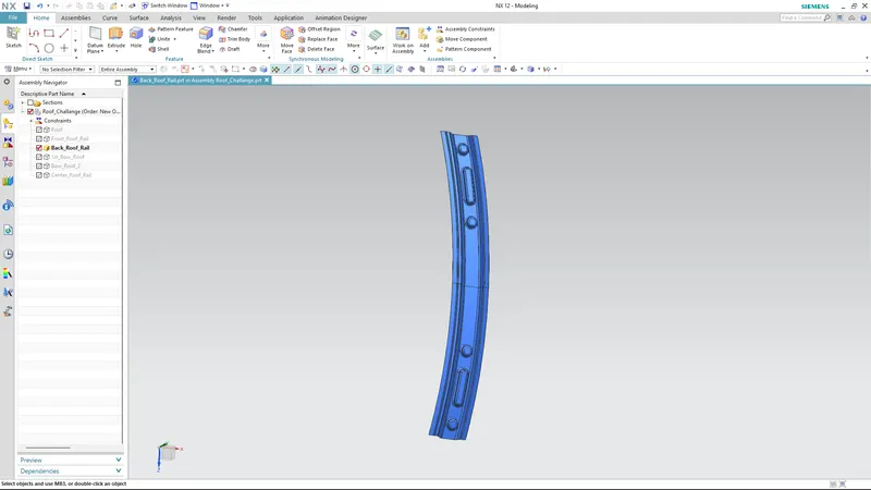
Figure: Top View of Rear Roof Rail
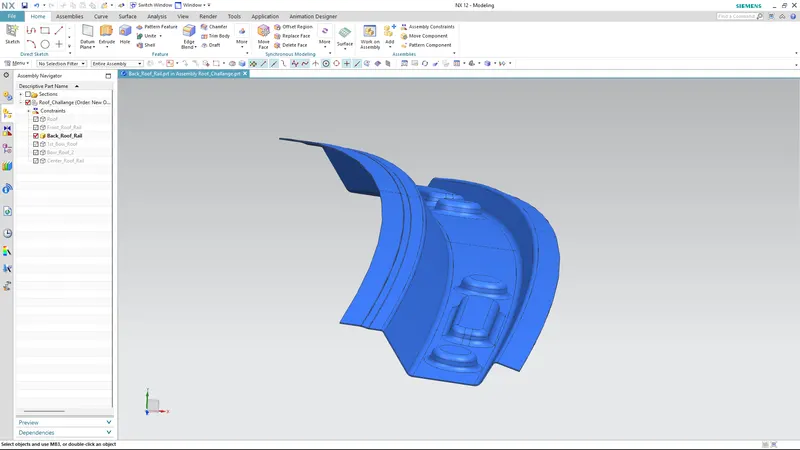
Figure: Side View of Rear Roof Rail
3. Bow Roof 1
The width of this section should be around 60-80mm. Most of this part is joined to roof outer surface with the help of mastic sealants and spot weld are done at the side flanges. Similar to the other design, we have to take into consideration of the headroom clearance and visibility criteria while designing.
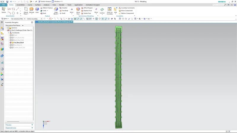
Figure: Top View Of Bow Roof 1
4. Bow Roof 2
The width of this section should be around 60-80mm. Most of this part is joined to roof outer surface with the help of mastic sealants and spot weld are done at the side flanges. Similar to the other design, we have to take into consideration of the headroom clearance and visibility criteria while designing.
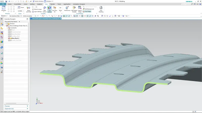
Figure: Cross-Section view of Bow Roof 2
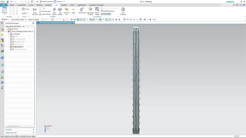
Figure: Top View of Bow Roof 2
5. Center Roof Reinforcement
It is the main supporting rof of the roof. this part is connected to the B pillar of the car so that during any accident most of the impact is absorbed by this section. The thickness of the reinforcement roof rail is 1.5mm. Also, the width of this section should be between 80-100mm. 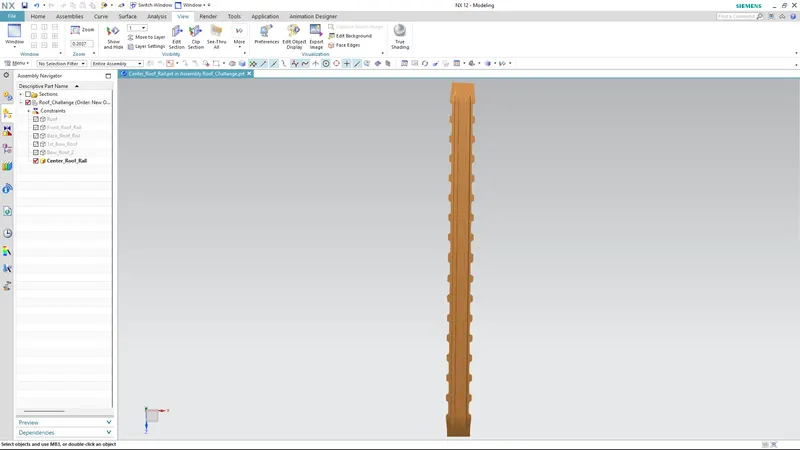
Figure: Top View of Center Reinforcement Rail
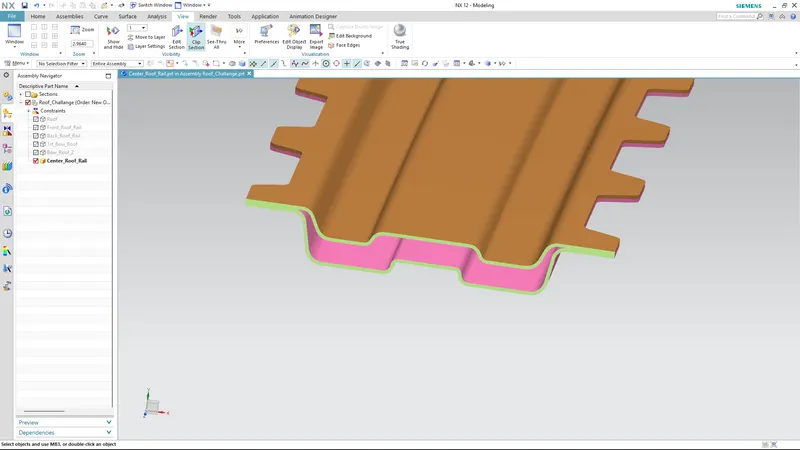
Figure: Cross-Sectional view of Center Reinforcement Rail
Draft Analysis:
Draft analysis is a method of checking the draft angle on various faces of a part in a particular direction. It should be more than 7 degrees. The following are the Draft Analysis of the roof rails:
1. Front Roof Rail
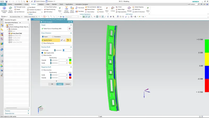
Figure: Draft Analysis of Front Roof Rail
2. Rear Roof Rail
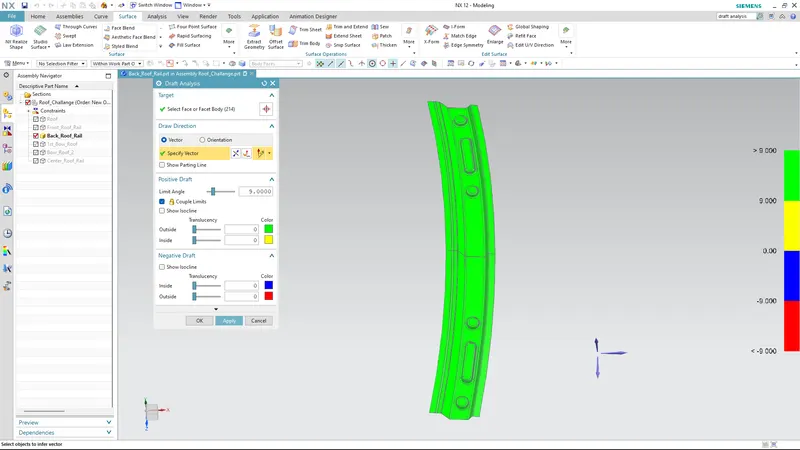
Figure: Draft Analysis of Rear Roof Rail
3. Bow Roof 1
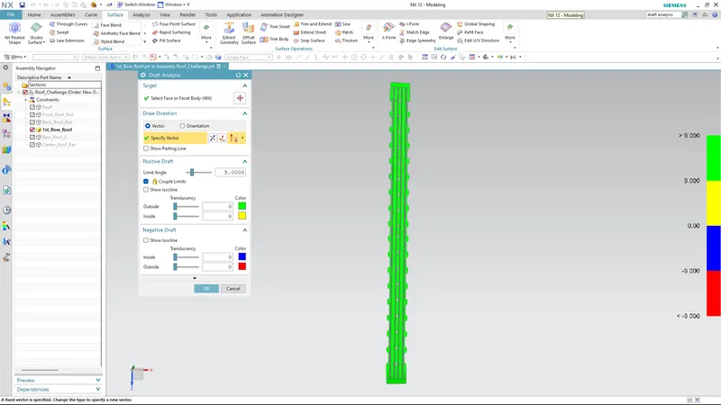
Figure: Draft Analysis of Bow Roof 1
4. Bow Roof 2
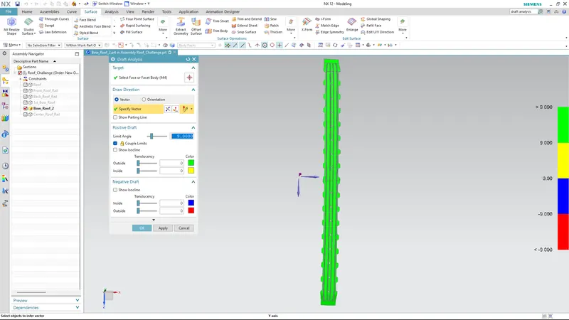
Figure: Draft Analysis of Bow Roof 2
5. Center Roof Reinforcement
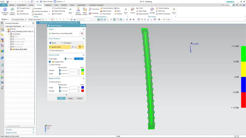
Figure: Draft Analysis of Center Roof Reinforcement
Section Inertia Analysis:
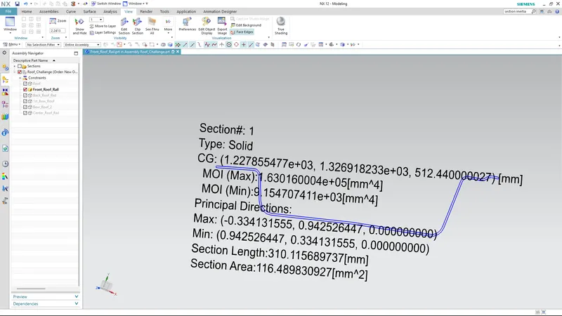
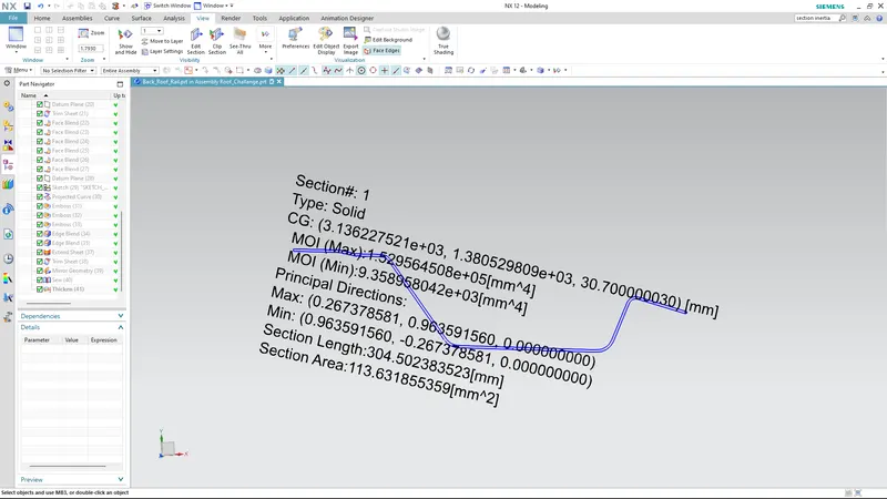
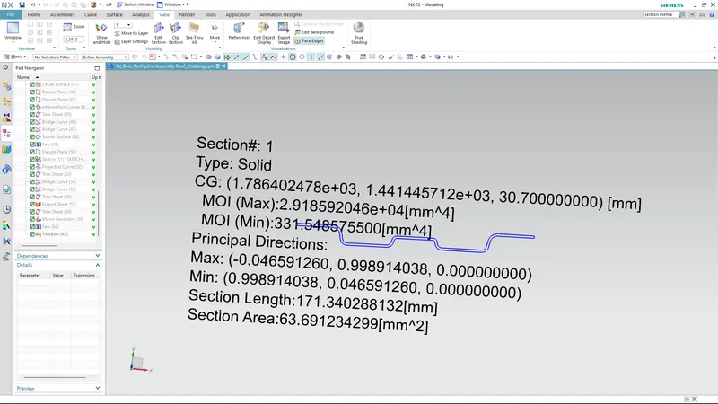
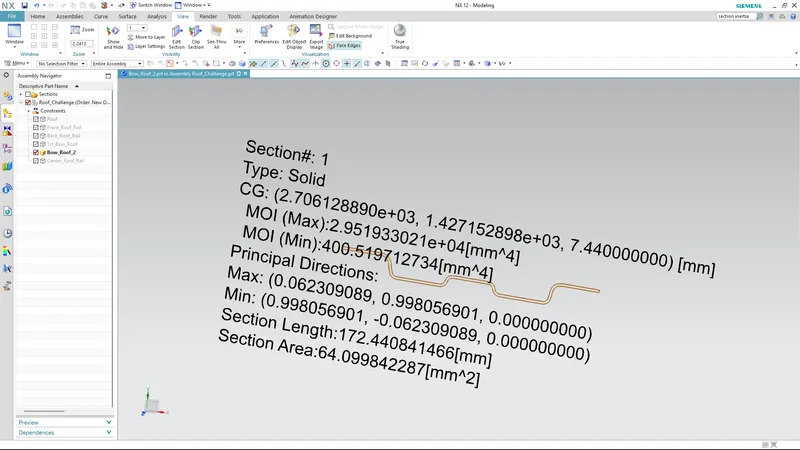
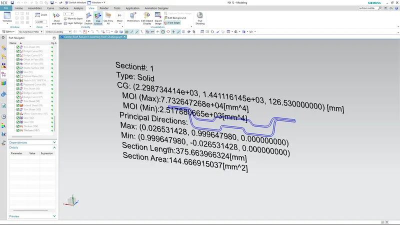
The Section Inertia Analysis of each roof rails are as follows:
1. Front Roof Rail
2. Back Roof Rail
3. Bow Roof 1
4. Bow Roof 2
5. Center Roof Reinforcement
Curvature Study and Calculations:
Basically, the curvature study is done to justify the positioning of the bow roofs. The most common criteria that must be fulfilled to justify the position of the bow roofs are as follows:
1. Heat Distortion Criteria
2. Snow Load Criterial
1. Heat Distortion Criteria
We use the given bow roof prediction formula for calculations;
W = [1.73 x 10^(-3) x L] + [1.85 x 10^(-8) x (R^2)/t] + [ 1.10x10^(-3) x l] - 2.68
Judgement Condition : OK< 2.7> 3.1
Where
L = Roof Length in X-Direction[mm](Roof dimension in 0-Y)
R = Roof curvature
R = 2(Rx*Ry)/(Rx+Ry)
Rx = X curvature
Ry = Y curvature
t = Roof plate thickness [mm]
l = Bow Roof Span [mm]
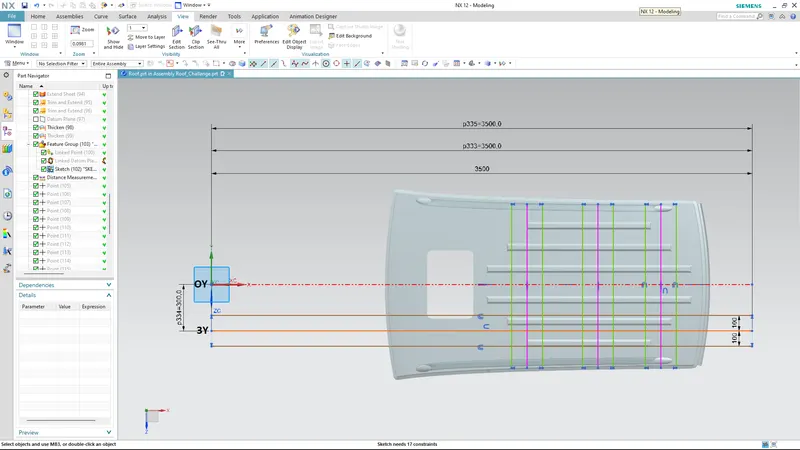
This analysis is done at 3Y which is 300 mm offset from OY line along the OX direction as shown in the figure, then this line is offsetted 100 mm in both the directions and necessary points are created.
From the model, we can obtain the values as shown in the figure:
Now, project the points on the roof surface and create arcs by using these points viz. Rx (along OX direction) and Ry (aong OY direction).
The values for Rx is as shown:
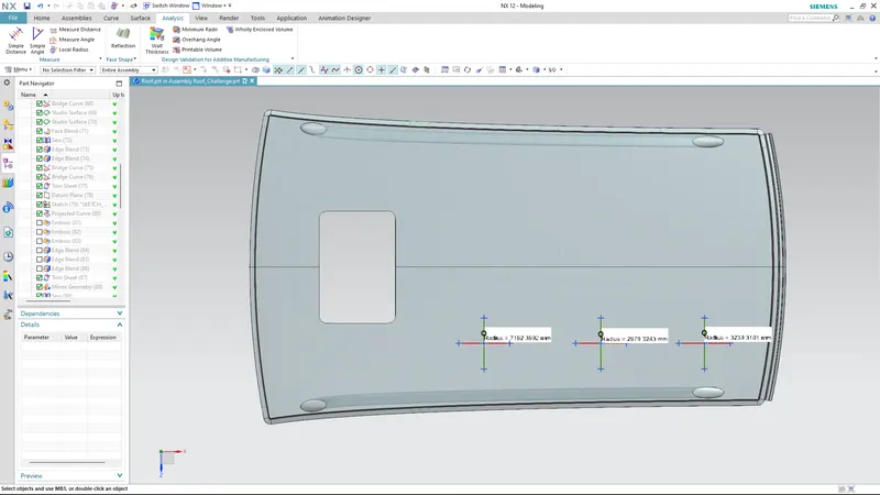
The values for Ry are as follows:
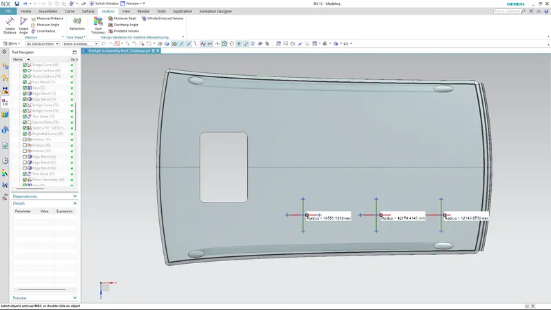
Heat Distortion Calculation Table:
| S.NO. | BOW | Rx (mm) | Ry (mm) | l (mm) | L (mm) | R^2/t (mm) | t (mm) | W (mm) | Remarks |
| 1 | 1st & CTR | 7,192.39 | 16,558.10 | 512.4 | 2030.5 | 134097090.6 | 0.75 | 3.88 | NOT OK |
| 2 | CTR & 2nd | 2,979.32 | 16,174.41 | 407.4 | 2030.5 | 33758681.65 | 0.75 | 1.90 | OK |
| 3 | 2nd & RR | 3,239.31 | 12,143.87 | 430.0 | 2030.5 | 34876116.48 | 0.75 | 1.95 | OK |
From the tabular column, the region between Bow Roof 1 and Center Roof Reinforcement donot fulfill the heat distortion criteria, therefore emboss is provided on the roof surface to increase the strength of the surface.
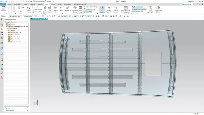
Also, from the figure below, sunroof is provided between the front roof rail and bow roof 1 therefore, there is no need to calculate the heat distortion at that region.
Snow Load Criteria:
The prediction formula for calculating the snow load criteria is as follows:
Qr = [Iy x t2] / [α x s x [(Rx + Ry)/2]2 x 10-8]
Note: The Qr value given over here is correct. There was a typo error in the formula given in the video.
Where
α = My x Lx2 x 10-12 , My = Y(Ly-Y)
Judgement condition = Qr ≥ 3.1
250 ≤ s ≤ 380
t = Roof plate thickness [mm]
Ly = Distance between the front and rear roof Rails on the Vehicle along with 0Y[mm]
Length of Roof panel with the center point between Roof rail Front /Rear as the front and rear reference point.
Lx = Distance between the Left and Right end of the roof on the Roof BOW [mm]
Width of the roof panel exposed on the surface.
Y = Distance front Front Roof Rail to Roof BOW[mm]
s = Distance for which Roof BOW bears divided load [mm]
s = L1/2 + L2/2
Iy = Geometrical moment of inertia of Roof BOW (Y cross-section )[mm4]
Rx = Lateral direction curvature radius of roof panel Y cross-section on Roof BOW [mm]
Roof panel curvature Radius of the Length Lx in Front view
Ry = Longitudinal Direction curvature radius of the Roof panel X cross-section on Roof BOW [mm]
Roof panel X curvature radius of length s in Side view
Snow Load Calcualtion Tabular Column:
| S.NO. | BOW | I (mm^4) | a | Lx (mm) | Ly (mm) | Y (mm) | s (mm) | Rx (mm) | Ry (mm) | t (mm) | Qr | Remarks |
| 1 | 1st & CTR | 2515 | 0.903 | 1077.4 | 2030.5 | 512.4 | 459.9 | 3860.6 | 7319.3 | 0.75 | 10.59 | OK |
| 2 | CTR & 2nd | 400 | 0.74 | 1055.2 | 2030.5 | 407.4 | 418.7 | 4327.75 | 12033.7 | 0.75 | 1.08 | NOT OK |
From the tabular column, The section between CTR and 3nd Bow Roof is not satisfying the criteria therefore, Emboss is provided to compensate for the values that are not satisfuing in the calculation part.
Conclusions:
Hence, the design of the Roof, Front Roof Rail, Bow Roofs and Reinforcement Roof Center is designed by following the Master Section with the design parameters for the given A surface.