Roof challenge
ROOF DESIGN:
Aim:
By using the styling surface of the roof, to create the roof with flanges on all sides and additional to the roof strength for various conditions, number of bow roofs, center reinforcements, Front roof rail and Rear roof rail has to create by analysing the following considerations and calculations,
- Heat Distortion Creteria
- SnowLoad Condition
- Visibility of the passenger towards the road
- Roof curvature study
Roof:
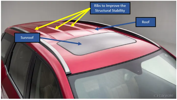
It is the important part of the car, because of it contribute in major aspects like funtional wise and the aesthetic wise also. The functional aspects of the roof are, to protect the passenger when the vehicle gets crashed due to the accidents or rollover, to protect the passenger from the outside environments, It Improves the structural rigidity of the vehicle. Depends upon the vehicle parameter and variant functions, roof design differs accordingly.
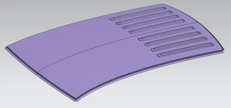
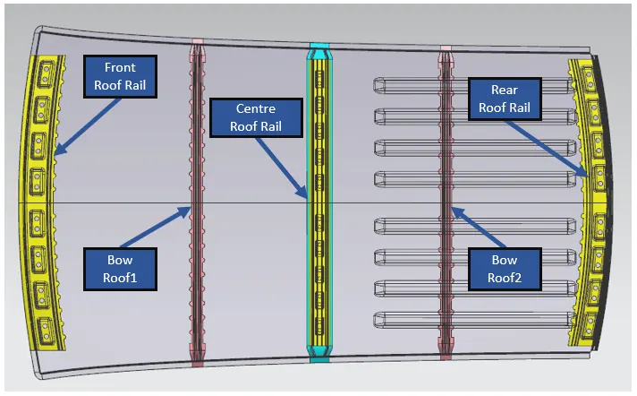
Types of Reinforcement added to the Roof Design:
- Front Roof Rail
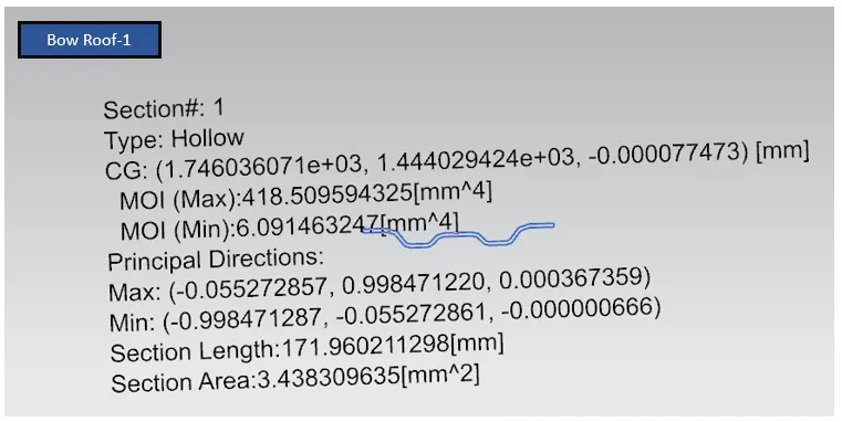
- Bow Roof1 - (BR1)
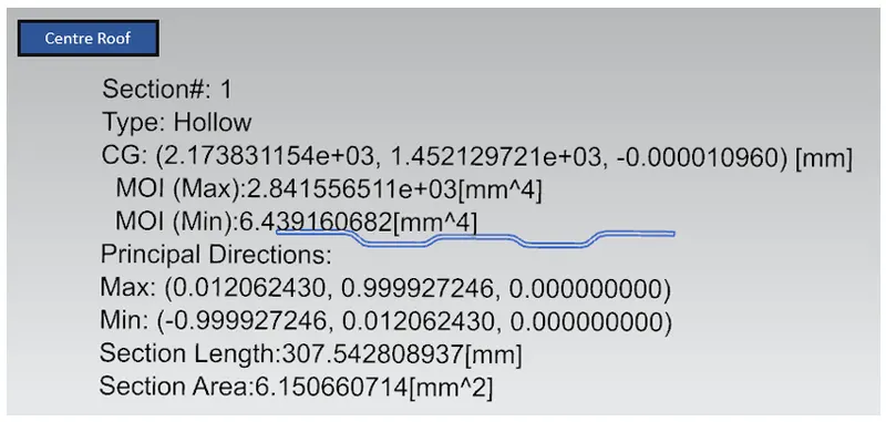
- Center Roof Rail - (CTR)
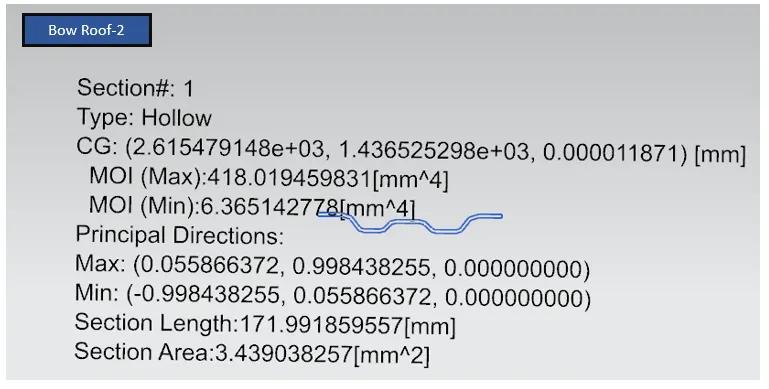
- Bow Roof2 - (BR2)
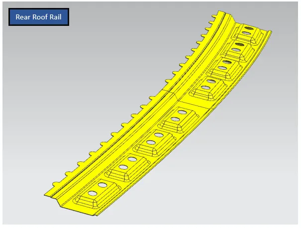
- Rear Roof Rail
Front Roof Rail:
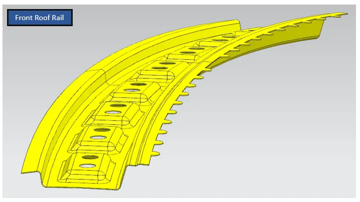
- Front Roof Rail is connected to the roof by spot welding and mastic sealants at forward side and rearward side of the roof rail respectively.
- According to the given master section input, by considering the Front passenger head room clearance and their vissibility, the Front Roof Rail has been created with the mentioned dimensions.
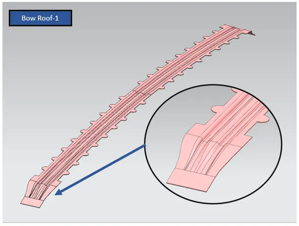
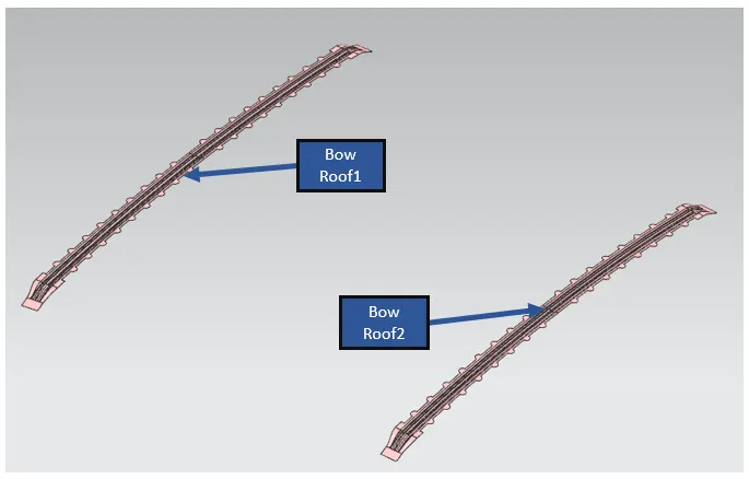
Bow Roof-1 (BR-1) and Bow Roof-2 (BR-2):
- It is the additional cross member to improve the strength of the roof. The roof length is equally separated according to the number of additional cross member to calculate the location of the Bow Roofs.
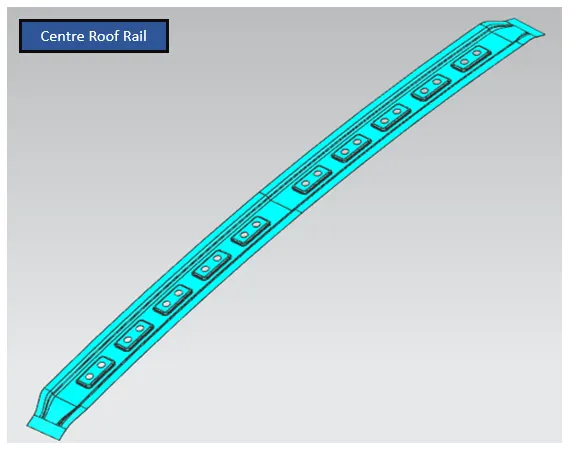
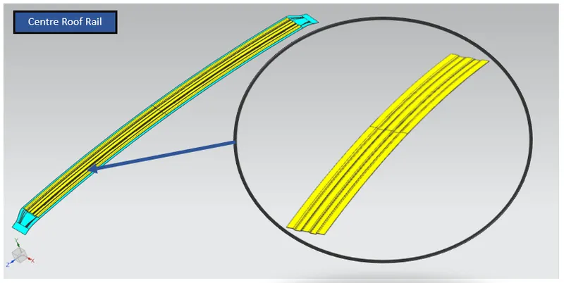
Centre Roof Rail (CTR):
- Centre Roof Rail is to be located at nearly to the the centre of the roof and it is connected to the roof by using the mastics sealeant instead of spot welding.
Rear Roof Rail:
- By considering the back door opening and closing criteria and the given master section, rear roof rail has been created.
- The rearward of the roof rail is connected to the roof by using spot welding and the forward of the roof rail is connected by the mastic sealants.
Calculation for Heat Distortion Criteria and Snowload Criteria:
Heat Distortion Criteria:
- According to the location of roof rails and the roof curvature, the roof design has been subjected to the heat distortion test by theoretically by using the below mentioned formulae,
- This is to be done for to check the ability of the roof to withstand in the heated temperature under load.
W = [1.73 x 10^(-3) x L] + [1.85 x 10^(-8) x (R^2)/t] + [ 1.10x10^(-3) x l] - 2.68
Judgement Condition : OK< 2.7> 3.1
Where;
L = Roof Length in X-Direction[mm](Roof dimension in 0-Y)
R = Roof curvature; R = 2(Rx*Ry)/(Rx+Ry)
(Rx = X curvature; Ry = Y curvature)
t = Roof plate thickness in mm,
l = Bow Roof Span in mm,
Represented the required datas to the formula, here is the result,
| Sl.No | Roof Rails | L(mm) | t(mm) | l(mm) | Rx(mm) | Ry(mm) | R(mm) | W | Result OK/Not OK |
| 1 | Front roof rail to Bow roof-1(BR-1) | 2033.2 | 0.75 | 466 | 5819.7 | 3638.60 | 4477.67 | 1.843 | OK |
| 2 | Bow roof-1(BR-1) to Centre roof(CTR) | 2033.2 | 0.75 | 363.9 | 4958.7 | 6932.8 | 5781.89 | 2.061 | OK |
| 3 | Centre roof(CTR) to Bow roof-1(BR-2) | 2033.2 | 0.75 | 377.8 | 4113.2 | 10412.9 | 5897.01 | 2.102 | OK |
| 4 | Bow roof-1(BR-2) to Rear roof rail | 2033.2 | 0.75 | 442.8 | 4002.2 | 13938.5 | 6218.5 | 2.27 | OK |
Snowload Criteria:
- Like heat distortion test, here also the roof design is subjected to test the snowload condition by using the following formulae,
- It is done to check the whether the roof can able to carry the snow without changing the shape or not.
Qr = [Iy x t2] / [α x s x [(Rx + Ry)/2]2 x 10-8]
Where; α = My x Lx2 x 10-12 , My = Y(Ly-Y)
Judgement condition = Qr ≥ 3.1; 250 ≤ s ≤ 380
t = Roof plate thickness in mm
Ly = Distance between the front and rear roof Rails along with 0Y in mm
Lx = Distance between the Left and Right end of the roof on the Roof BOW in mm
Y = Distance front Front Roof Rail to Roof BOW in mm
s = Distance for which Roof BOW bears divided load in mm
s = L1/2 + L2/2
Iy = Geometrical moment of inertia of Roof BOW (Y cross-section )(mm^4)
Rx = Lateral direction curvature radius of roof panel Y cross-section on Roof BOW in mm
Ry = Longitudinal Direction curvature radius of the Roof panel X cross-section on Roof BOW in mm
| Sl.No | Roof Rails | t(mm) | Iy(mm^4) | Rx(mm) | Ry(mm) | Lx(mm) | Ly(mm) | L1(mm) | L2(mm) | S(mm) | Y(mm) | My(mm^2) | α(mm^4) | Qr(mm^-1) | Result OK/Not OK |
| 1 | Front roof rail to Bow roof-1(BR-1) | 0.75 | 418.509 | 4339.3 | 3604.2 | 1124.4 | 2033.2 | 547.5 | 427.9 | 215.22 | 547.5 | 813420.75 | 0.9598 | 6.745 | OK |
| 2 | Bow roof-1(BR-1) to Centre roof(CTR) | 0.75 | 2841.55 | 4187.1 | 6881.9 | 1086.3 | 2033.2 | 427.9 | 441.7 | 221.81 | 427.9 | 686907.87 | 0.8105 | 29.027 | OK |
| 3 | Centre roof(CTR) to Bow roof-1(BR-2) | 0.75 | 418.019 | 4229.8 | 7125.1 | 1063.84 | 2033.2 | 441.7 | 515.7 | 258.70 | 441.7 | 702965.55 | 0.795 | 3.546 | OK |
| 4 | Bow roof-1(BR-2) to Rear roof rail | 0.75 | - | 4197.8 | 15491.2 | 1050 | 2033.2 | 515.7 | - | - | 515.7 | 782574.75 | 0.862 | - | - |
Section Modulus:
Images of Roof Design:
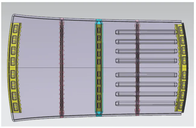
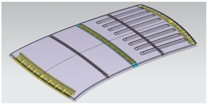
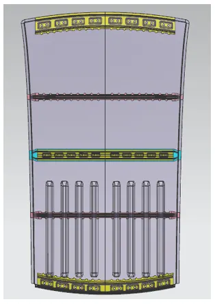
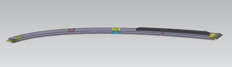
Conclusion:
Here the Roof Design has been created by considering the various design consideration like Heat Distortion Creteria, SnowLoad Condition, Roof curvature study and Visibility of the passenger towards the road by using NX-CAD Software.