Week 8 - Challenge 2 - Base Bracket Design
Report - Tooling Axis Creation and Draft Analysis of BASE BRACKET:
Tooling Axis Creation of BASE BRACKET:
- In this component we can understand by visually, that the component is symmetry in Y direction along with ZX plane.
- Creating the Dummy Tooling axis - Boundaries of the Base Bracket has been projected from the Class A Surface using Boundary command and Disassembled it in a simpler curves. Then point has been created at the centre of the curve. Using that point Dumming tooling axis has created by the line command.
- Projection of Intersecting Line - Plane has been created along with the Point which we created and the YZ Plane. Then projected the insecting line with that plane using Intersect command.
- Bisecting Line Creation - To create the bisecting line, Draft line has been created along with the surface of the component by using the intersect line points at each end(y+ and y-). Using that two Draft lines, Bisecting line has created by Line command. This bisecting line will be the tooling axis of the component..
Draft Analysis of BASE BRACKET:
- Material Mode has been ensured in the View Mode Customization to proceed the Draft Analysis.
- The Draft Analysis can be done by using the Feature Draft Analysis command.
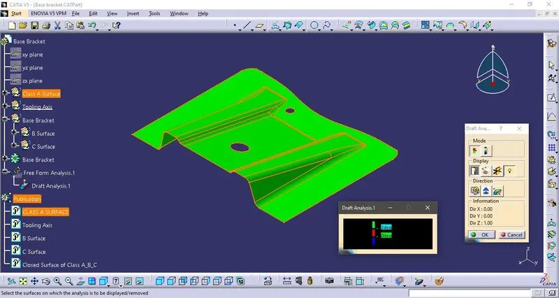
- To analyse the draft, the compass should be drag and fix it in the tooling axis, click on the lock button which is in the feature draft analysis toolbar then click on the component surface.
Then the Draft result will be showcased by the comparison of different colours. It has been resulted in Blue colour, so that the direction has flipped to get the correct draft analysis result. - Green colour mentions that the draft angle is more than 2degree, Red colour mentions that the draft angle is 0 to 2 degree and Blue colour mentions that the draft angle is in Negative.
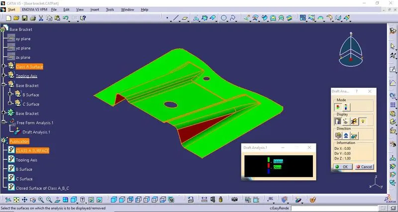
- If the Draft Analysis value is changed into 16degree, the draft angle will be resulted in red colour.
- Also we can measure the surface angle in the component by using Analysis Under Running Point Command.
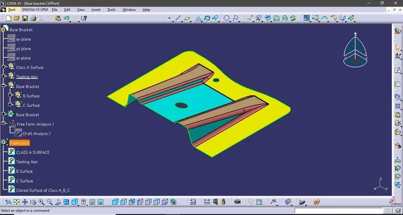
This Draft analysis will be saved in the Model Tree when we click ok
Images:
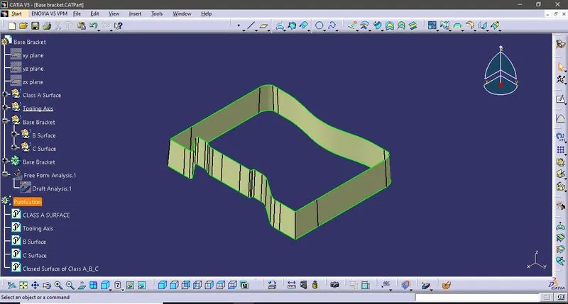
- Draft Analysis
- Draft Analysis (Draft Value 16degree)
- Class A Surface
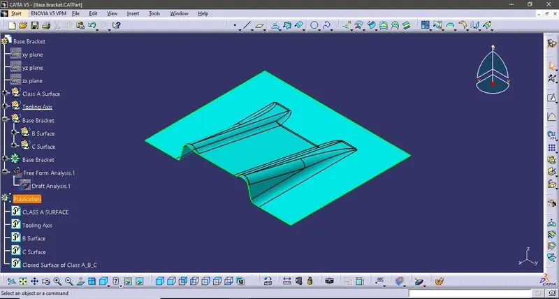
- Class B Surface
- Class C Surface
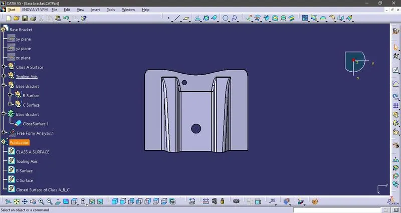
- Closed Surface of Class A,B and C
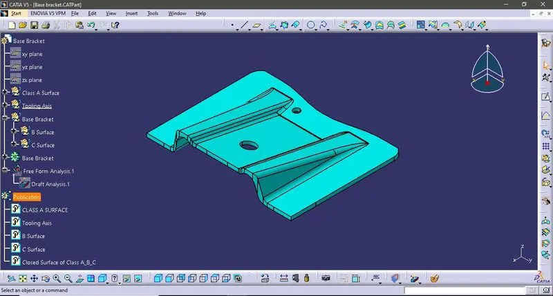
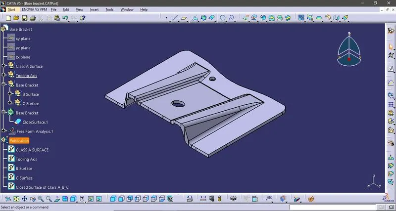
- Solid Base Bracket - Isometric View
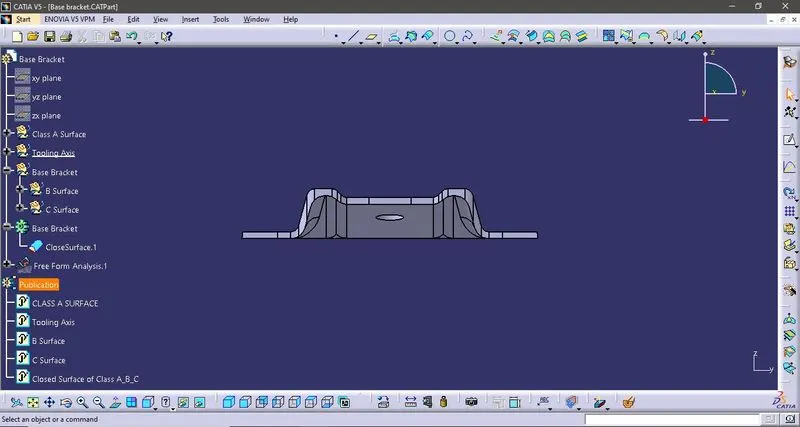
- Solid Base Bracket - Front View
- Solid Base Bracket - Top View