Week 8 - Challenge 3 - Switch Bezel Design
Report - Tooling Axis Creation and Draft Analysis of SWITCH BEZEL:
Tooling Axis Creation of SWITCH BEZEL:
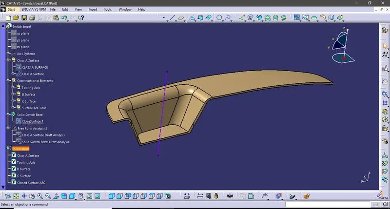
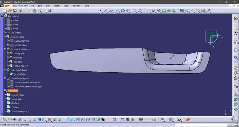
- In this component(Switch Bezel), Pocket area is the complicated one to make this component. The Pocket area has faces in 3 sides only. So that The Tooling Axis has been created by considering this pocket.
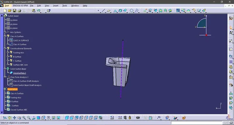
- Draft Angle Line in YZ - Base Surface has extracted and the point has been created on the middle of the surface. Position Sketch is created along the YZ Plane with that Point which we created. Draft angle line has drawn on the intersecting surface line along with YZ plane. Then the Bisecting Line has created with these draft angle lines. This Bisecting line is the Tooling clearing axis in Y direction.
- Draft Angle Line in XZ - In this we dont have two draft faces, so that one draft angle line has created on the intersecting surface line along with XZ plane. Another draft angle line has created along with the point which we created and 6degree with respect to draft angle line. Then the Bisecting line has created with thes draft angle lines. This Bisecting line is the Tooling clearing axis in X direction.
- Tooling Axis - It has been done by creating the bisecting line between the Tooling clearing axis in X and Y direction.
Draft Analysis:
- Material Mode has been ensured in the View Mode Customization to proceed the Draft Analysis.
- The Draft Analysis can be done by using the Feature Draft Analysis command.
- To analyse the draft, the compass should be drag and fix it in the tooling axis, click on the lock button which is in the feature draft analysis toolbar then click on the component surface.
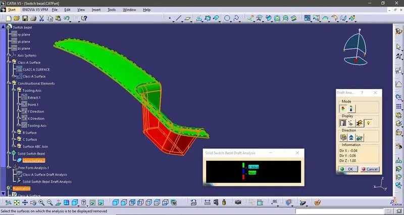
Then the Draft result will be showcased by the comparison of different colours. - Green Colour - More than 2.9degree
- Blure Colour - 0 to 2.9degree
- Red Colour - Negative degrees
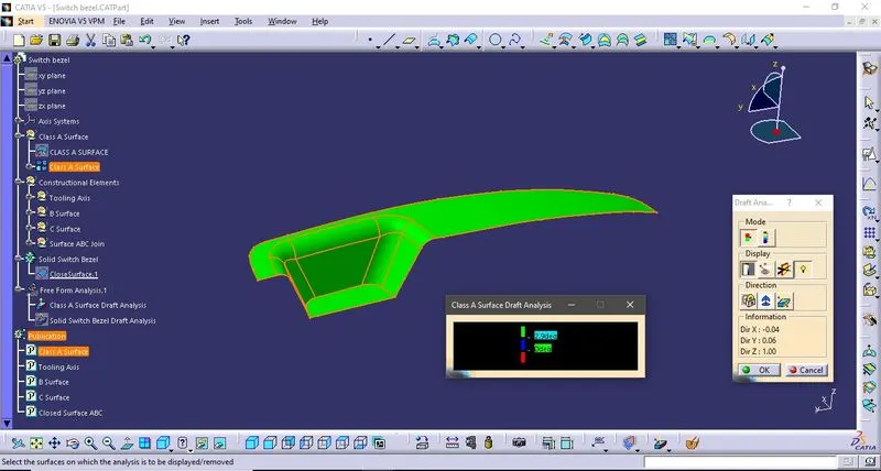
- It can be done in Class A Surface and the Solid Switch Bezel. The Resultant has Been attached in the Images.
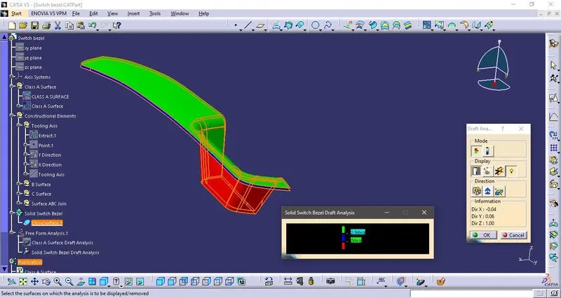
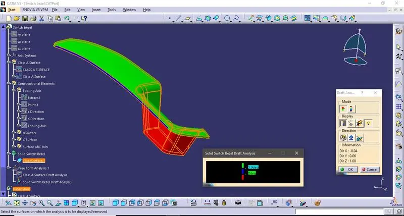
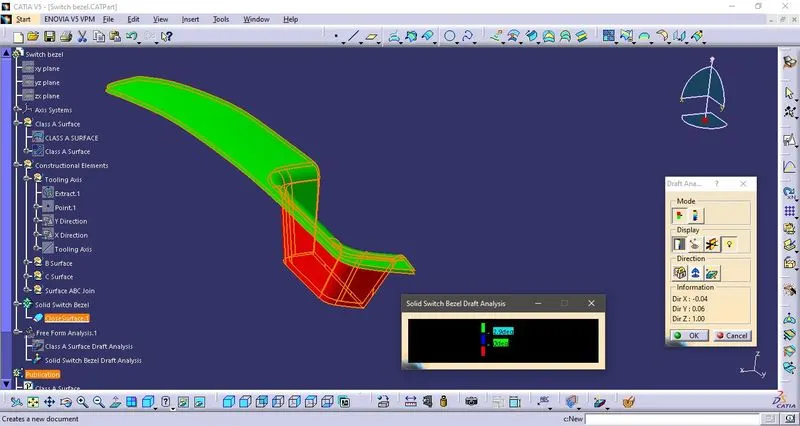
- In Solid Switch Bezel Draft Analysis, If the resultant draft angle is not in the Green, then we should adjust the degree of draft angle line which we created in the X direction. Initially draft angle line has made with 3degree, then the result has received not in the Green. So that we changed the degree of draft angle line to "6", then the result has been received in Green. Untill the degree draft angle line is 5.8, the result has received in Blue.
Images:
- Draft Analysis of Class A Surface
- Draft Analysis of Solid Switch Bezel(Draft angle line degree at "3")
- Draft Analysis of Solid Switch Bezel(Draft angle line degree at "5.8")
- Draft Analysis of Solid Switch Bezel(Draft angle line degree at "5.9 & 6")
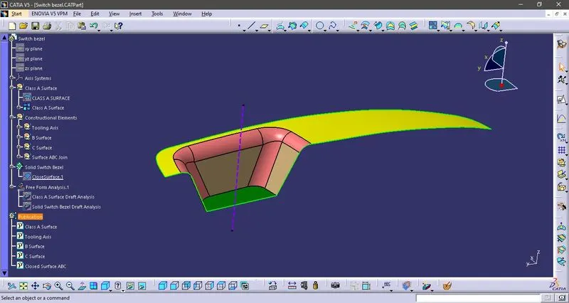
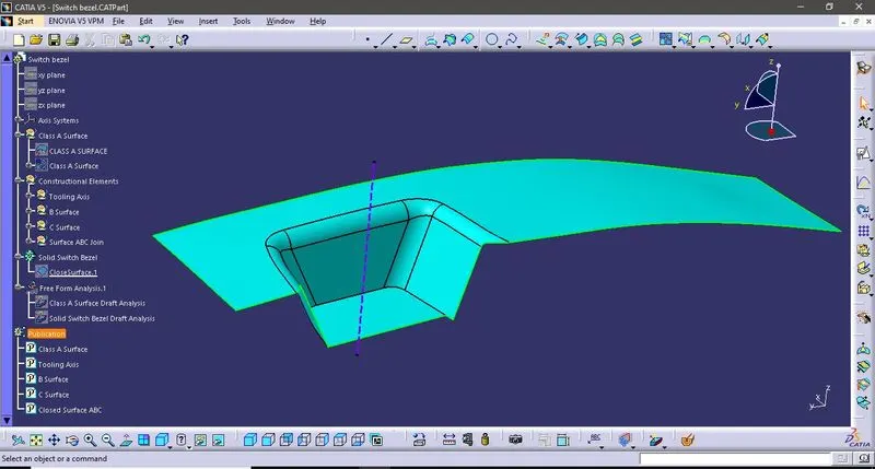
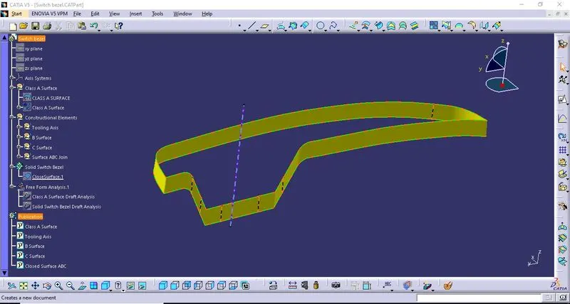
- Class A Surface
- Class B Surface
- Class C Surface
- Closed Surface of Class A,B and C
- Solid Base Bracket - Isometric View
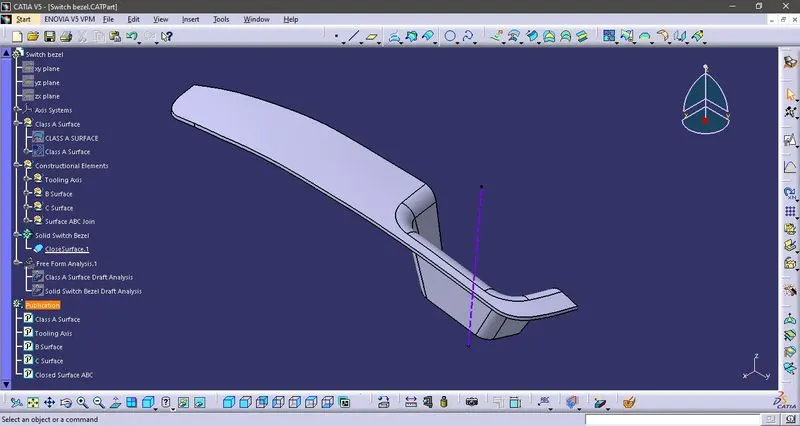
- Solid Base Bracket - Normal to Tooling Axis
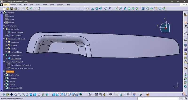
- Solid Base Bracket - Front View
- Solid Base Bracket - Top View
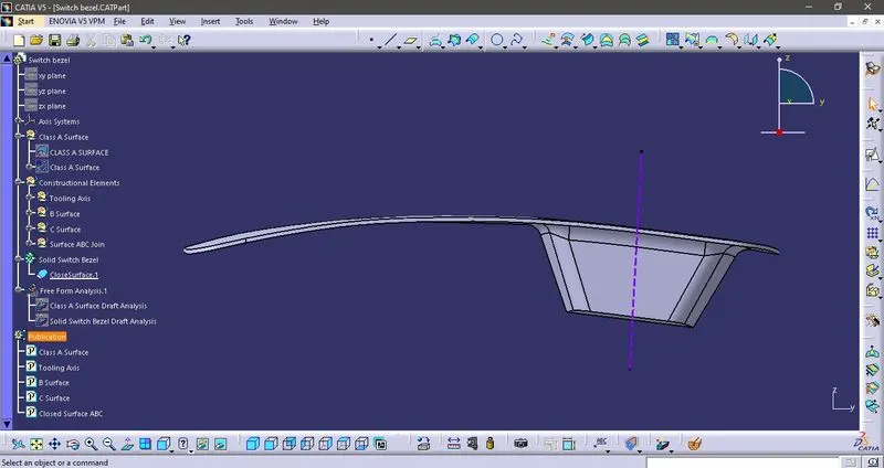
- Solid Base Bracket - Side View