Roof challenge
WHAT IS MEANT BY A CAR ROOF?
- The use of aluminum for the car roof is well established in all-aluminum car body designs.
- But there are also significant aluminum applications in the roof of vehicles
with steel car body structures. - Weight reduction in the roof (i.e. lowering the center of gravity)
has always been a high-priority topic in automotive design. - However, the roof is generally an
integral part of the body-in-white. - Therefore, the integration of structural aluminum
components into the roof of a steel body structure requires an in-depth consideration of
different aspects (as outlined below).
Aluminum Roof on a steel body:
- The substitution of the steel roof panel by a lightweight aluminum alloy roof panel is an
attractive option to optimize the mass distribution in a car. However, if the remainder of the
vehicle body structure continues to be fabricated in steel, two major hurdles have to be
overcome. - The first problem is the realization of a reliable joint between the different
materials. Various technologies have been developed to join aluminum to steel; in most
cases, adhesive bonding combined with a mechanical joining technique is applied, but also
friction stir welding, soldering, or fusion welding methods have been developed. - If the mixed material joint is properly protected to avoid any danger of galvanic corrosion, a safe and
the durable joint is achieved. - The other problem is the different thermal expansion coefficients of aluminum and steel. The
combination of the aluminum alloy roof attached to the steel body may create compressive
stresses in the aluminum roof when the body is subjected to elevated temperatures such as
those required to cure the paint applied to the assembled body in white. Visible thermal
distortions of the roof panel, if any, are not acceptable. Such effects can be eliminated (or
minimized) for example by the use of an aluminum alloy with a higher strength level, the
selection of an appropriate adhesive, the application of proper joining procedures.
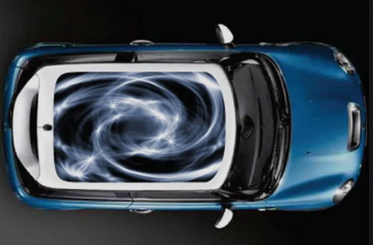
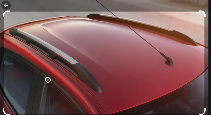
OBJECTIVE:
- The objective of this project is to design and develop A car roof with essential flanges and reinforcements like ditch area, front roof rail, Bow roof rail 1 and center reinforcement rail, Bow roof rail 2, and Rear roof rail for the given styling surface.
- we should perform a curvature study on a roof and we need to calculate the Heat distortion values and snow load criteria to determine whether the bow roof is at the correct position or not in a prescribed manner.
- Finding out the moment of inertia, section modulus of bow roof 1, bow roof 2, and front roof and rear roof components.
- Finally, perform the draft analysis for each reinforcement.
INTRODUCTION:
With the growing concerns on energy conservation and vehicle emission, it is increasing pressure on vehicle manufacturers internationally to provide lighter-weight components for vehicles. In order to minimize energy consumption, lightweight has become a critical issue because weight is a key factor for fuel consumption. The lighter the vehicle more will be the fuel efficiency. Generally, the lightweight design can be addressed from three aspects of applications of novel materials, structural optimization, and advanced processing technology, of which novel material application is counted as the most effective approach. Plastics and their forms have been increasingly used in the automotive industry for their advantages of lightweight, corrosion resistance, and easy manufacturing.
But along with these advantages of lightweight, corrosion resistance, and more fuel efficiency, safety is a very important criterion for vehicle manufacturers. Vehicle rollover crashes are frequent accidents worldwide. Vehicle rollover crashes are the cause of many fatalities and severe head, neck, and spine trauma around the world. Since 2000 in the United States alone, more than 10,000 people every year have been killed in vehicle rollovers [4]. Therefore, passenger safety is an important issue in the automotive industry, and this concern is gradually growing every year. Guaranteeing the physical safety of passengers is not only a marketing consideration but has also become an obligation stipulated by international standards that are now in place in several countries as well as a requirement by governmental organizations. According to a survey of the literature regarding rollovers accidents, passengers can be ejected, partially ejected, or become the victims of roof intrusion, all of which may be fatal. For this reason, the Federal Motors Vehicle Safety Standards enacted Regulation No. 216 and ECE R66 are the standards for the vehicle strength of superstructure to provide protection to occupants during rollover accidents through the provision of survival space.
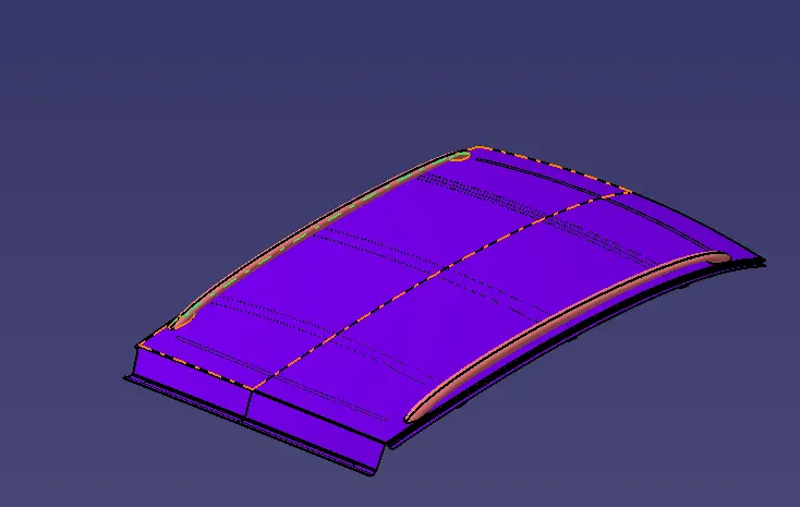
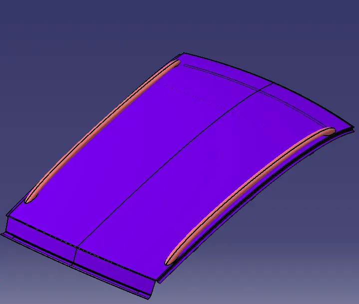
The below image shows the project of roof design with the given product which we are going to develop.
AUTOMOTIVE VEHICLE ROOF:
Safety point of view vehicle roof plays a very crucial role, especially rollover kind of accidents, in which vehicle tips over onto its side of the roof. And vehicle rollover crashes are the causes of many fatalities and several head, neck, and spine trauma around the world. Therefore passenger safety is also a very important parameter in front of OEMs. It is not only a marketing strategy but also it is an obligation stipulated by international standards that are now placed in several countries, as well as a governmental requirement. For this reason, strength is a very important criterion for designing a vehicle roof.
Standard experimentation roof set up for roof creation follows the below method:
The strength of the roof structure to occupant protection in real-world rollover crashes, requiring the maximum moving distance of the roof structure should be less than 127 mm (5 in.) when the induced load is 1.5 times the vehicle weight. For the test, the passenger car shall be rigidly placed or positioned on a horizontal surface with the doors locked and the window closed. Furthermore, a flat, rigid block with a lower surface a rectangle measuring 30 inches wide by 72 inches long (762mm X 1829mm) shall not move more than 5 inches(127mm), measured as the distance between the original location of the lower surface of the test device and its location as the specified force level is reached, when it is used to apply a force of 1.5 times the unloaded vehicle weight(UVW) or 5000 lbs(22224N), whichever is less, to either side or forward edge of the vehicle. This test can be conducted on either side of the roof structure, the front left or the front right side but not on both sides in one single test and still meet the requirements of the test.
The orientation of the test device is mentioned below:
- The longitudinal axis of the plate is pitched forward at a 5 º angle as viewed from the side of the passenger car.
- The lateral axis or the roll of the plate is such that it forms a 25 º outboard angle with a horizontal surface as viewed from the front of the passenger car.
- The lower surface of the plate shall always maintain a tangential contact with the surface of the roof.
- The initial point contact is 10 inches (254 mm) from the leading edge of the plate and in line with the longitudinal axis on the lower side of the plate.
Importance of providing the reinforcements for the roof:
If the roof is flat it is very weak and cannot be able to withstand the load like snow load, heat distortion. so in order to increase the strength of the roof, we will provide the reinforcements like front roof rail, bow roof rail 1, center roof rail, bow roof rail 2, and rear roof rails are introduced and joined together by the different joining methods for the flat roof of the component.
Different types of reinforcements that have are below:
1) Front Roof Rail.
2) Bow Roof Rail 1.
3) Center Roof Rail.
4) Bow Roof Rail 2.
5) Rear Roof Rail.
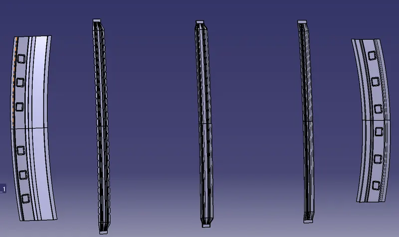
Front roof rail:
The front roof rail is the main which joins the wind shied glass, body outer and inner panel also with the hemming operation. The front roof rail is designed from the given master section as follows.
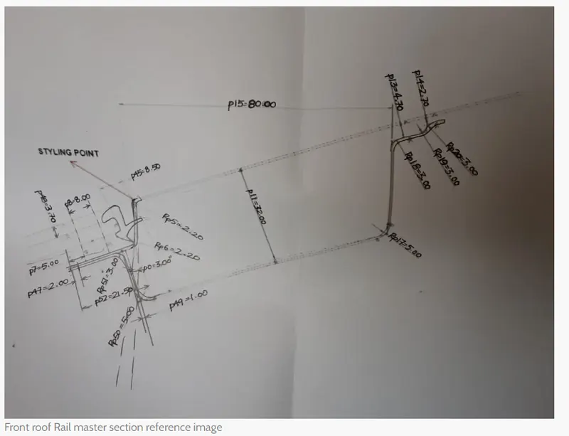
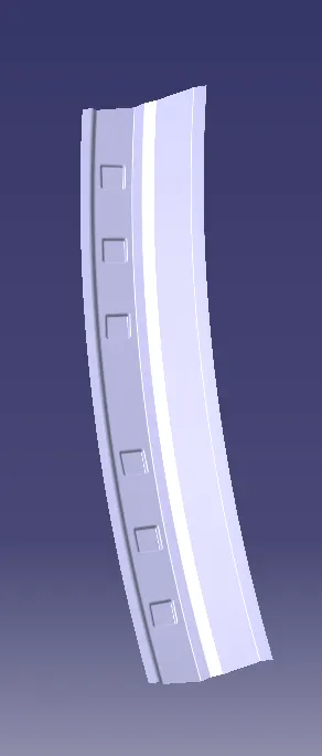
The front roof rail is created according to the given master section and provides a thickness of 0.75mm inwards which follows the distance between the roof outer panel and the created front roof rail.
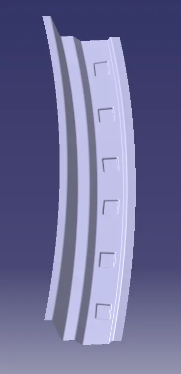
Rear Roof Rail:
The rear rail roof is the one that joins the back door and the body's outer side of the component.
The master section for the rear roof rail is given as follows.
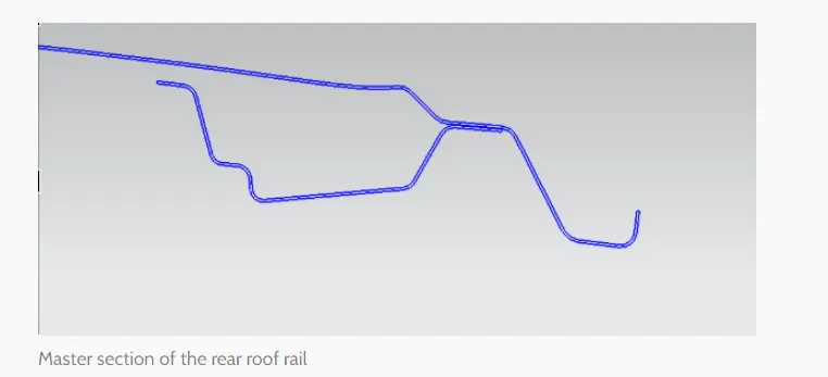
Center Roof Rail:
Center roof rail is the one that provides support to the flat areas of the roof components and gives more strength to withstand the load distortion criteria of the roof. The center roof rail is connected at the center of the roof which is gonna connect to the B-pillar component to withstand the load being situation. This center rail roof helps in providing strength at the center of the roof during the rollover test.
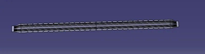
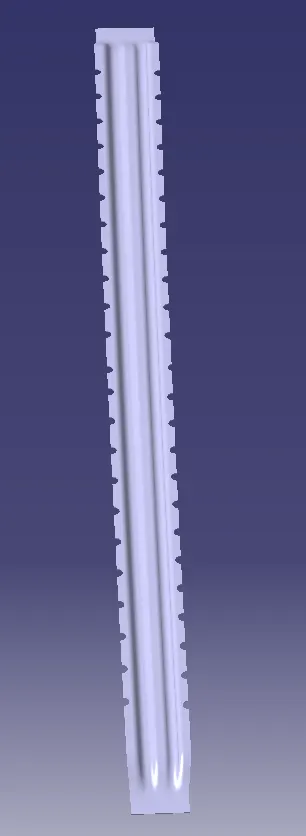
Bow Roofs:
The bow roofs are added or created to improve the torsional stiffness and load-bearing capacity of the roof structure. we can add bow roofs based on the size and length of the roof component.
Joining process:
The mastics are introduced in between the outer panel, bow roofs, and center reinforcements for the joining process. The usage of mastics will improve the remarkable strength of the roof structure.
Spot welding or laser cutting operations are introduced for the joining of the outer panel and reinforcement of the roof structure.
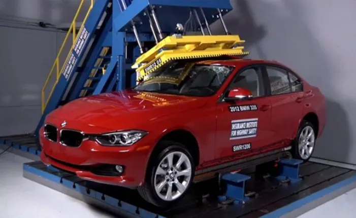
How Roof Crash Test is done in the industry is shown in the below figure:
Roof crash test is the design given by the IIHS( INSURANCE INSTITUTE OF HIGHWAY SAFETY). after analyzing many accidents on a road crash of cars this IIHS has given the ratings and its importance of creating the safety precautions for the design and development of a roof.
IIHS gives the rating based on this test.
How fast the car can reform its original shape after the rollover test conducted on the car.
How deep is the protrusion after the roll-over test?
Conditions to follow the roof crash test:
First condition:
- close and lock all the doors.
- close all the windows.
Second condition:
Fix the body sill or chassis frame on a hard lever surface horizontally.
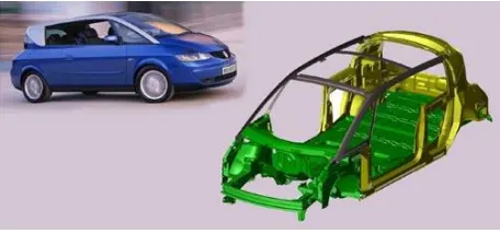
The roof structure of the component is given by the application of aluminum material and its outer body panel is shown in the below figure.
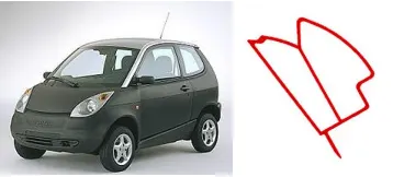
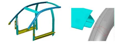
The integration of structural aluminum components into the roof of a steel car body was first attempted in the Ford THINK, a small electric city car. The cant rail of this vehicle, i.e. the structural member which runs over the top of the doors, is designed as a visible aluminum component. The extruded aluminum profile (alloy EN AW-6060) includes the A-pillar and ends at the top rear end. The length of the beam is about 2.2 m, the profile has a hollow cross-section with flanges and it is 3-dimensionally formed. The beam upper face is exposed to the atmosphere and the surface is untreated.
3D SKETCH BENDING EXTRUSION OF ALUMINUM ROOF OF CAR ANALYSIS:
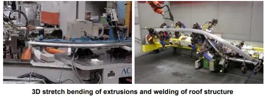
- The aluminum extrusions are formed by three-dimensional stretch-bending. This process
allows minimizing spring back effects and leads to components with good geometrical
precision. - The aluminum components are joined by MIG arc welding; the welding sequence has been
selected to minimize distortion of the parts. The aluminum roof structure assembly is then
joined to the steel structure by adhesive bonding and self-piercing riveting.
Heat Distortion study of a Roof:
The heat distortion study plays an important role in sheet metal usage. The heat distortion temperature is the temperature above which the metal cannot be used for the structural applications of the sheet metal components. This study helps to provide the heat distortion temperature at which the material starts to soften when exposed to a fixed load at elevated temperatures. In order to avoid bending on a roof, this study help us to create the bow roofs on a roof compartment to provide the strength to the roof structure to overcome the uncertainties like bending, extrusion, and heat dissipated over the design of the roof part.
Heat distortion can be calculated by using the below formula:
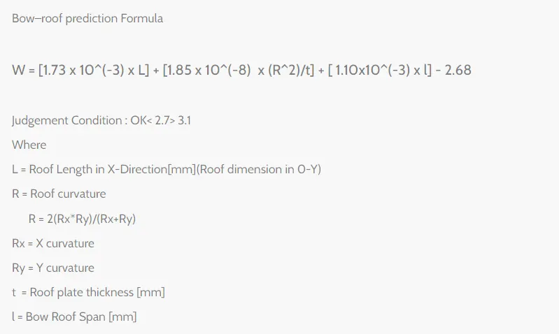
The judgment condition is: OKAY<2.7>3.1
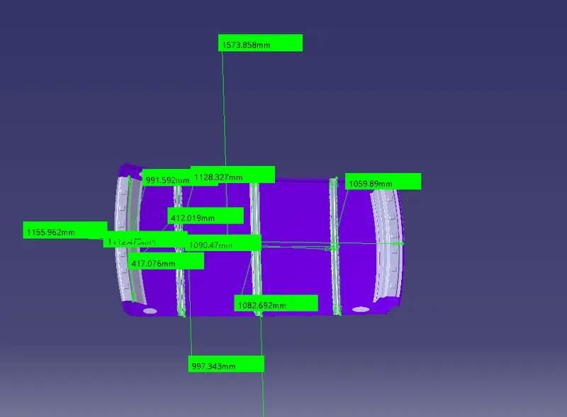
Apply all the values in the given formula to get the W values which lie in between <2.7>3.1.

From the above calculation, we came across that we get the W value in the prescribed given range which is less than 2.7 and more than 3.1, which is standardly applicable in the industry.
The Snow load criteria can be calculated according to the given formula and as shown in the below figure:
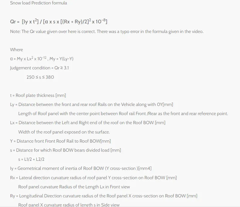
This is done when how the roof behaves when there is a snow area how strong it can withstand by absorbing the snow conditions. due to the snow rate, the dent will happen on the roof compartment. but the roof should be designed in such a way that it should withstand the snow load criteria and provide a fine strength to overcome the snow load distortion uncertainties over a snow load area.
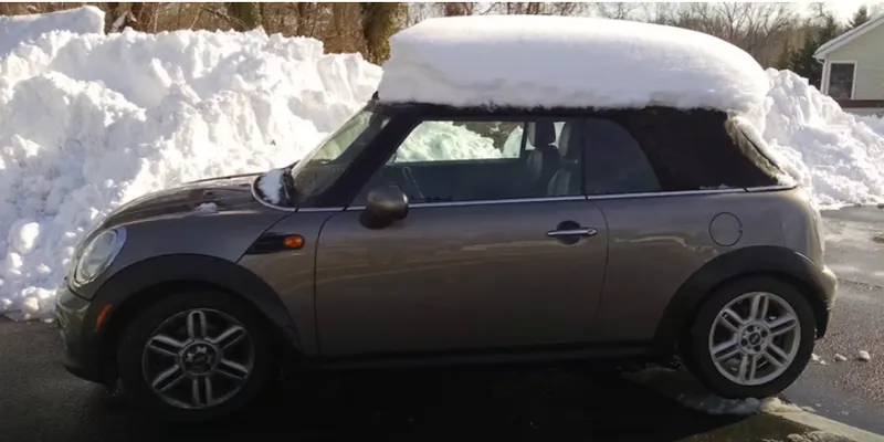
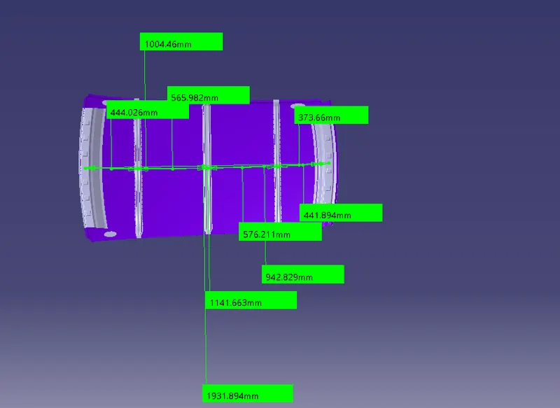
Applying all the values in the to get the Qr value more than 3.1

Section modulus calculations for roof structure:
The elastic section modulus is defined as S = I / y, where I is the second moment of area (or moment of inertia) and y is the distance from the neutral axis to any given fiber. It is often reported using y = c, where c is the distance from the neutral axis to the most extreme fiber, as seen in the table below.
Section modulus is the geometric property for a given cross-section used in the design of a beam and flexural members. other geometric properties used in these conditions are tension & shear, the radius of gyration for compression, a moment of inertia, and polar moment of inertia for stiffness. any relation between these properties is highly dependent on the given question.
There are two types of section module :
1) The elastic section modulus and
2) Plastic section modulus.
The Elastic section modulus is defined as
S=I/Y
Where,
S= section modulus.
I= Second Moment of inertia.
Y= The distance from the neutral axis to the given fiber element. it is often given as Y=c. where c, is the distance from the neutral axis to the most extreme fiber.
Section Modulus Calculation for BOW ROOF 1:
Created the section modulus calculation for bow roof 1 and shown in the below diagram.
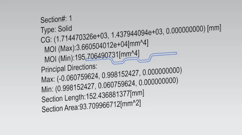
Moment of inertia maximum,(Max)Imax=3.6605*10^4(mm^4).
Moment of inertia minimum,(Min)Imin=195.7064(mm^4).
section modulus
S=I/Y
Y=34.95
S=Section modulus.
I=Moment of Inertia.
Y=Center form the neutral axis from the bow roof
From the formula,
Smax= 3.6605*10^4/34.95=1034.75mm^3.
Smin=195.7064/34.95=5.5mm^3.
Section modulus calculation for Bow Roof 2:
Created the section modulus calculation for bow roof 2 and shown in the below diagram.
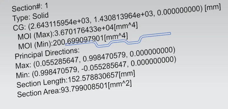
Moment of inertia maximum,(Max)Imax=3.6707*10^4(mm^4).
Moment of inertia minimum,(Min)Imin=200.699(mm^4).
section modulus
S=I/Y
Y=34.98
S=Section modulus.
I=Moment of Inertia.
Y=Center form the neutral axis from the bow roof
From the formula,
Smax=3.6707*10^4/34.98=1049.21mm^3.
Smin=200.699/34.98=5.735 mm^3.
Section modulus calculation for center roof rail:
Created the section modulus calculation for bow roof 2 and shown in the below diagram.
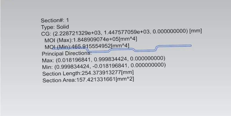
Moment of inertia maximum,(Max)Imax=1.8498*10^4(mm^4).
Moment of inertia minimum,(Min)Imin=465.9155(mm^4).
section modulus
S=I/Y
Y=59.96
S=Section modulus.
I=Moment of Inertia.
Y=Center form the neutral axis from the bow roof
From the formula,
Smax=1.8498*10^4/59.98=308.555mm^3.
Smin=465.9155/59.98=7.77mm^3.
Section modulus calculation for front roof rail:
Created the section modulus calculation for bow roof 2 and shown in the below diagram.
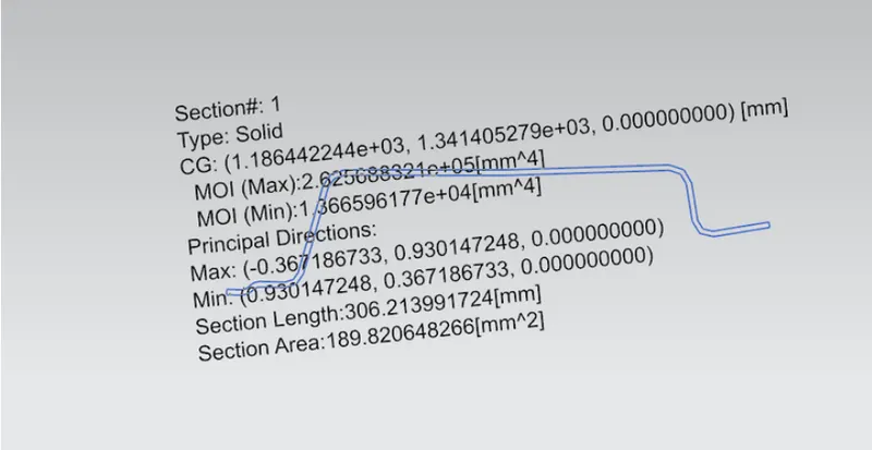
Moment of inertia maximum,(Max)Imax=2.625688*10^5(mm^4).
Moment of inertia minimum,(Min)Imin=1.3665961*10^4(mm^4).
section modulus
S=I/Y
Y=61.6899
S=Section modulus.
I=Moment of Inertia.
Y=Center form the neutral axis from the bow roof
From the formula,
Smax=2.625688*10^5/61.6899=4256.26mm^3.
Smin=1.3665961*10^4/61.6899=221.526mm^3.
Section modulus calculation for Rear roof rail:
Created the section modulus calculation for bow roof 2 and shown in the below diagram.
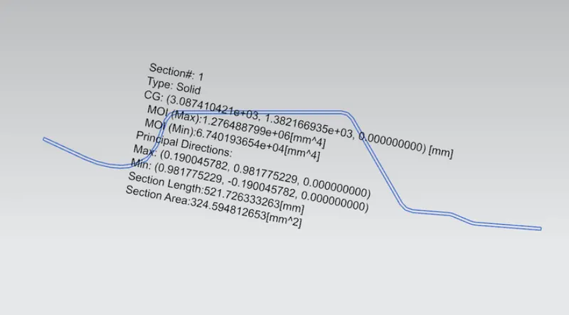
Moment of inertia maximum,(Max)Imax=1.276488*10^6(mm^4).
Moment of inertia minimum,(Min)Imin=6.7401936*10^4(mm^4).
section modulus
S=I/Y
Y=111.256
S=Section modulus.
I=Moment of Inertia.
Y=Center form the neutral axis from the bow roof
From the formula,
Smax=1.276488*10^6/111.256=11473.43065mm^3.
Smin=6.7401936*10^4/111.256=605.8273mm^3.
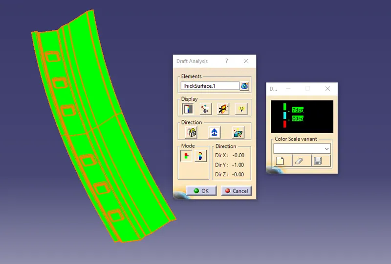
Draft analysis:
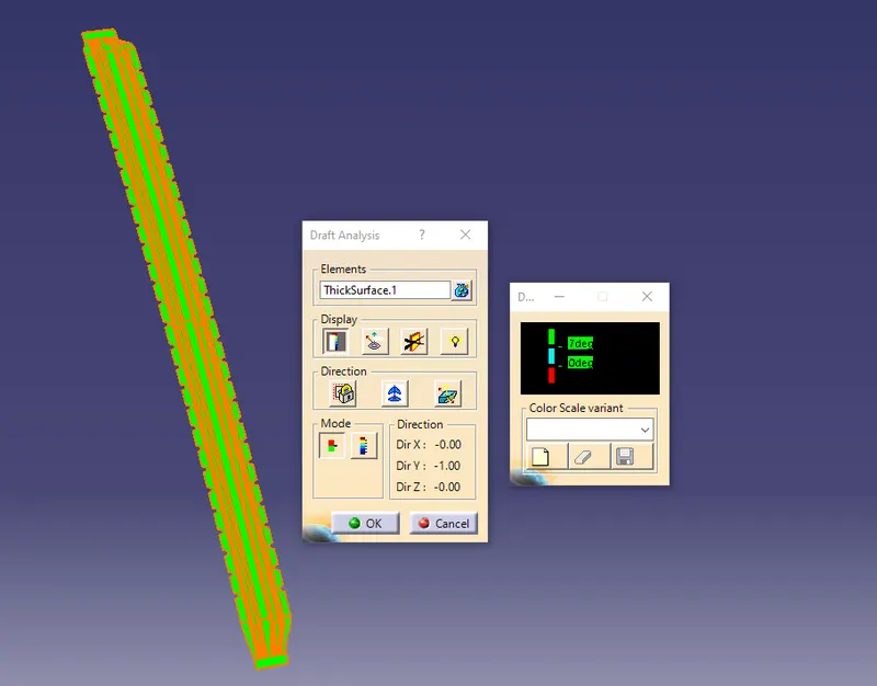
Draft analysis is a command that enables to detect the part created is easily removable or ejected or not. This type of analysis is conducted based on the color ranges identifying zones on the analyzed where the deviation from the draft direction at any point, corresponding to the specified values and draft is to be done on each part of the roof and always follows the draft angle of 7-degree draft direction which is able to produce the constructed part.
Draft analysis for the Front roof rail is shown in the below figure:
Draft analysis for the Bow roof rail 1 is shown in the below figure:
Draft analysis for the Bow roof rail 2 is shown in the below figure:
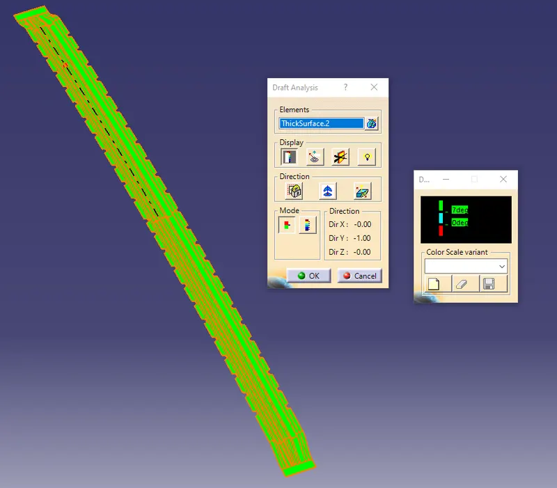
Draft analysis for the Center roof rail is shown in the below figure:
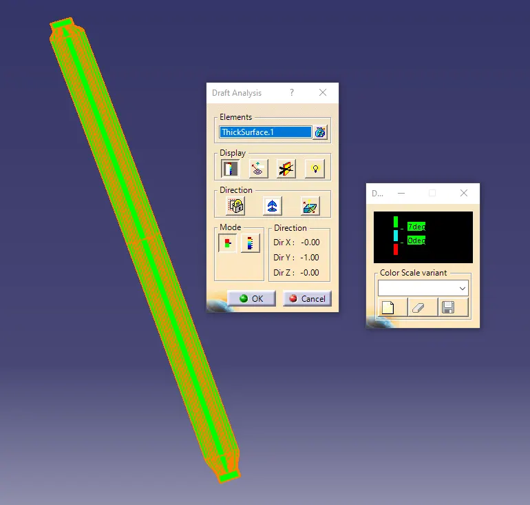
Draft analysis for the Rear roof rail is shown in the below figure:
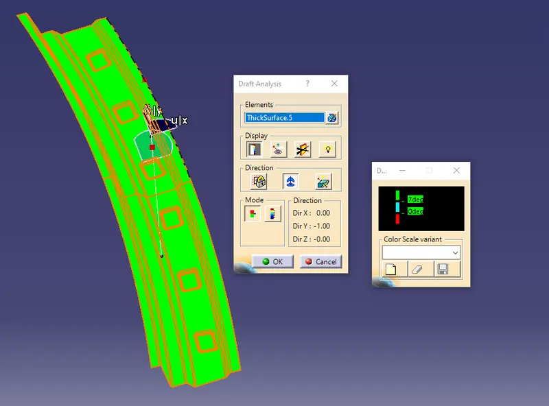
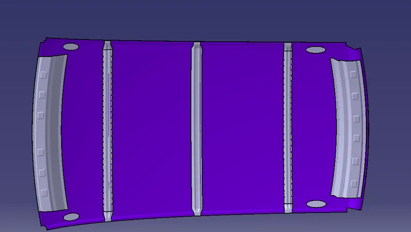
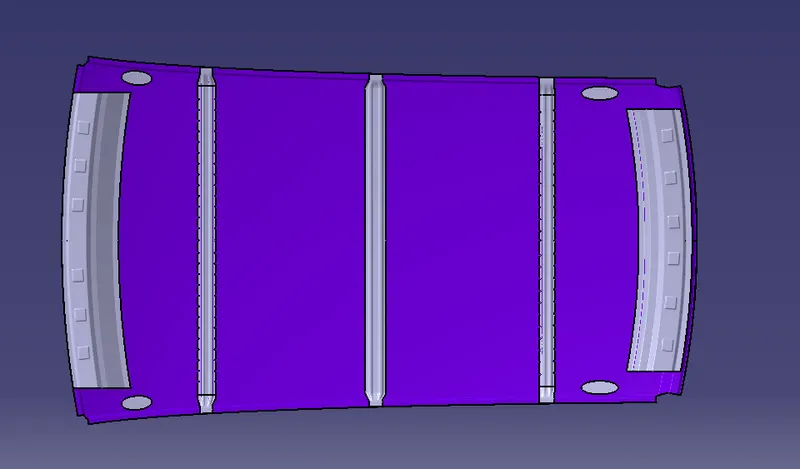
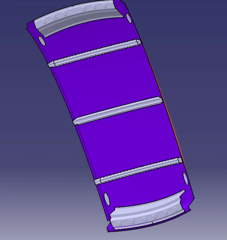
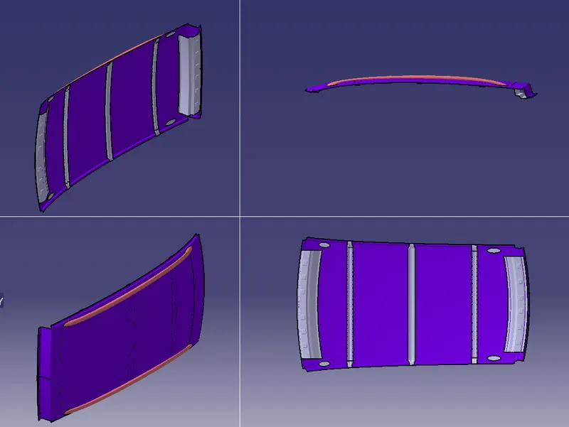
The images of Roof structures are shown in the below figures:
Front view:
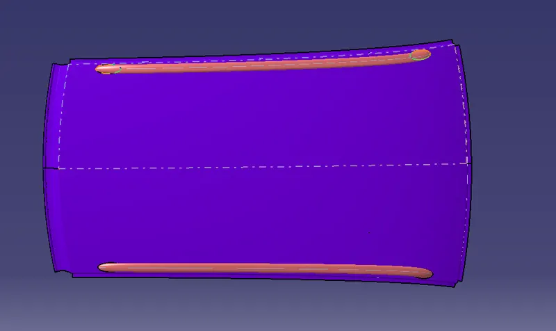
Left View:
Top View:
Multi Views of Roof structure:
Conclusion:
- Finally, the Roof structure is created and the Front roof rail, Bow Roof Rail 1, Bow Rail Roof 2, Centre Roof Rail, and Rear roof rail were created according to the master section.
- Calculated the section modulus for all the roofs, a moment of inertia and draft analysis for the created part also carried out and finally check the feasibility conditions for the roof.