Roof challenge
DESIGN OF ROOF
Introduction:
The roof of a car is a part of the vehicle that sits on top of the passenger compartment, protecting the vehicle from sun, rain, wind, Etc.,
The roof can be designed in many ways as it depends on the manufacturing capabilities and the design functions. The main parts of a roof will always stay the same so as to ensure the stability and the strength of the car without compromising the aesthetics of the car.
Objective:
Our main objective in the course is to design the roof supporting structures using the given data and to calculate the strength and performance of the roof.
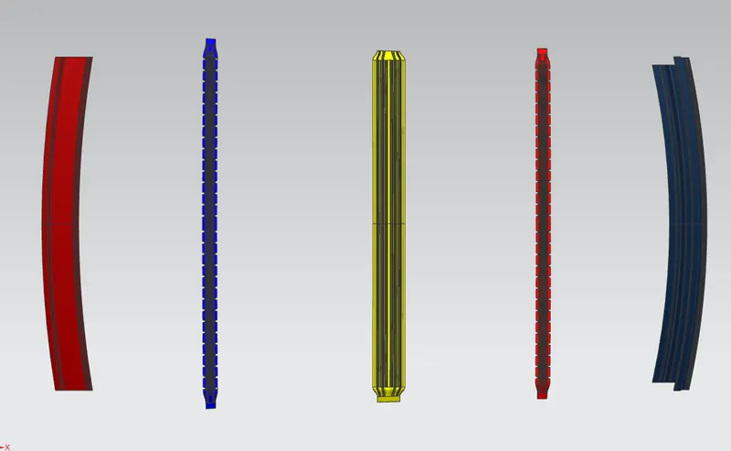
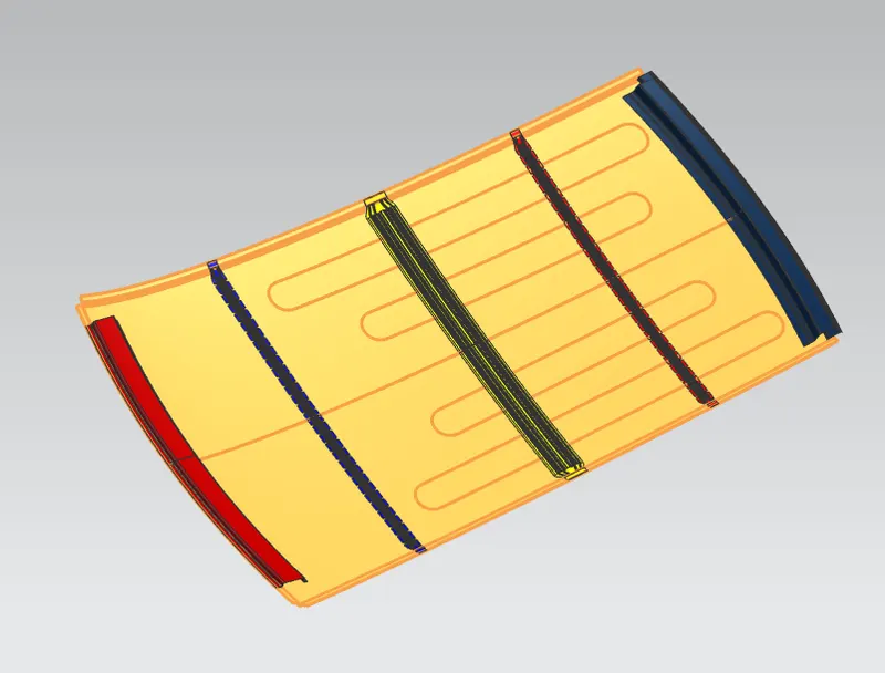
The main parts of a roof are;
- Front Roof Rail
- Bow Roof Rail (There can be n number of Bow roof rails as per the requirements)
- Center Roof Rail
- Rear Roof Rail
To do a curvature study on the roof and perform calculations for Heat distortion and Snow Load criteria, which is used to determine the position of the bow roofs.
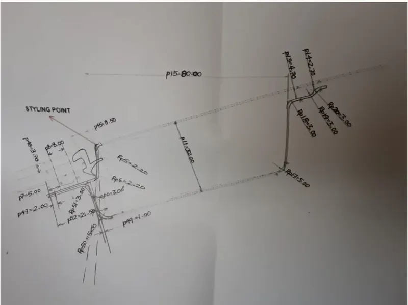
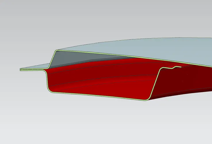
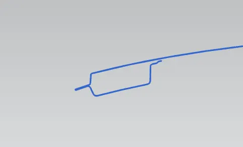
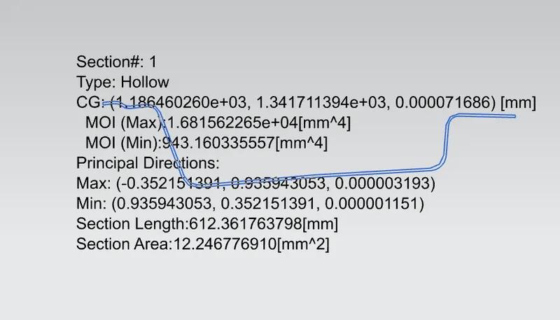
1. Front Roof Rail
This is the front part of the roof which enables it to fix itself to the body of the car, it is mounted along with the front windshield and is also dependent on the visibility of the passenger.
Here the front roof dimensions are given and designed as per it.
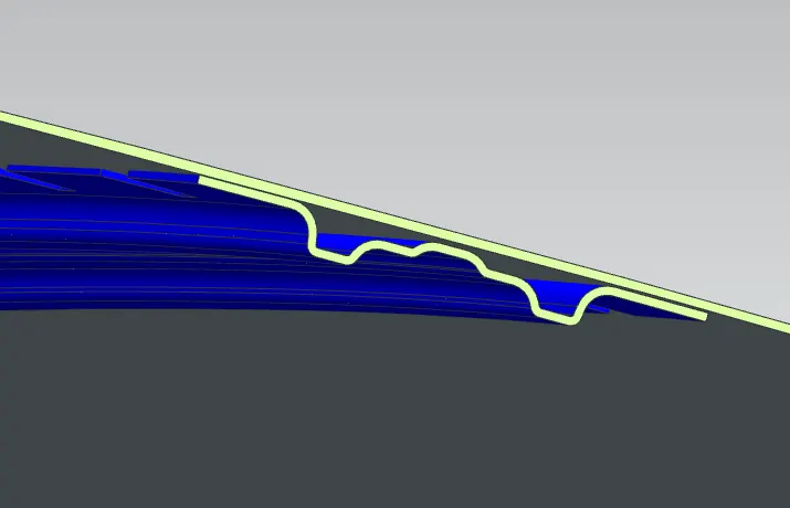
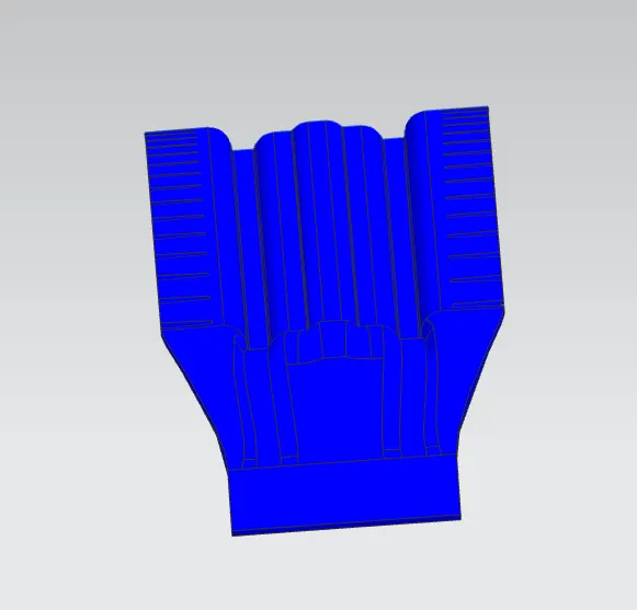
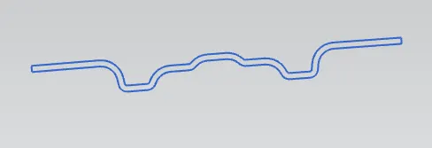
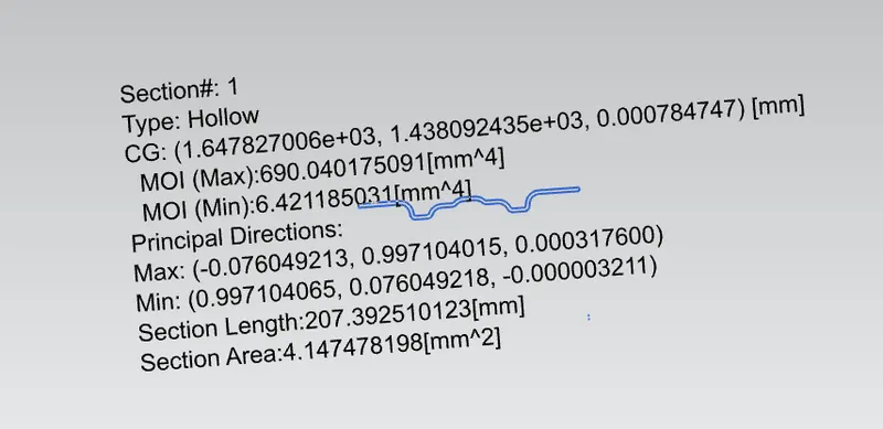
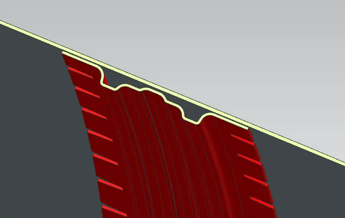
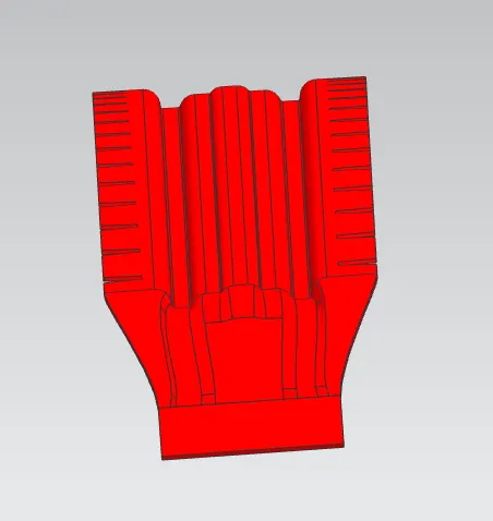
2. Bow Roof Rail 1
TThis part of the roof is designed to improve the stability of the roof and is placed before the center roof rail, the number of bow roofs to be used are dependent on the strength of the roof, the greater the stability the lesser the bow roofs required.
3. Center Roof Rail
Center Roof Rail is located at the center of the roof and is based upon various factors such as headroom clearance and visibility criteria.
Spot welds cannot be used for this process so Mastics are used for hodling them together.
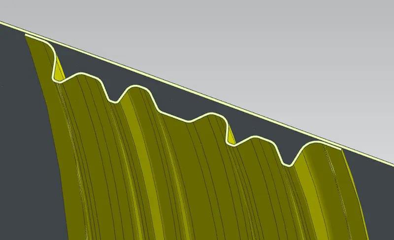
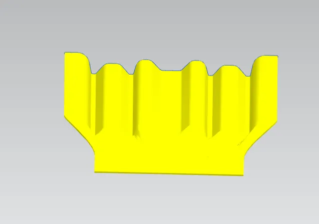
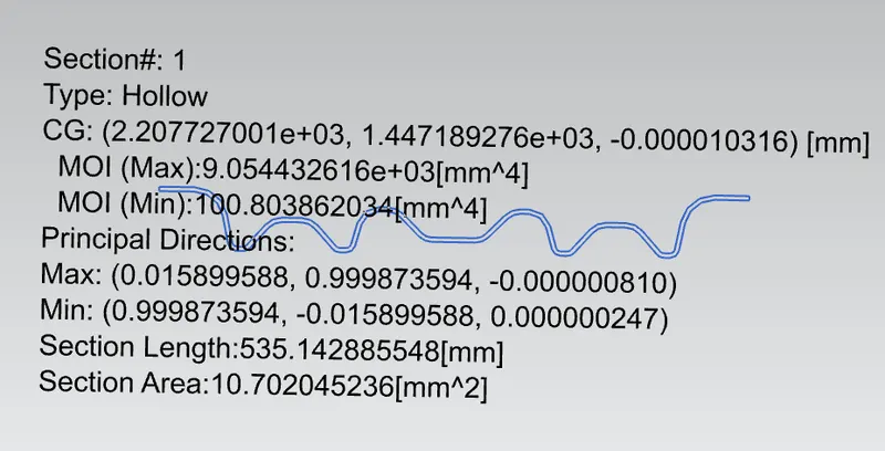
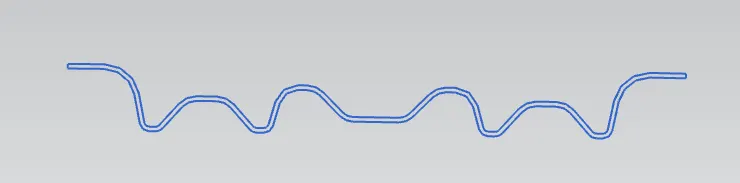
4. Bow Roof Rail 2
5. Rear Roof Rail
This is again designed as per the design requirements and similar factors are taken into consideration.
It is attached to the rear Windshield and is designed in such a way that the Rear Bonnet doesnt interfere with it.
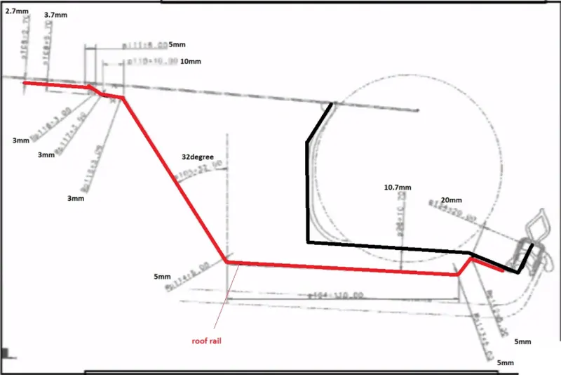
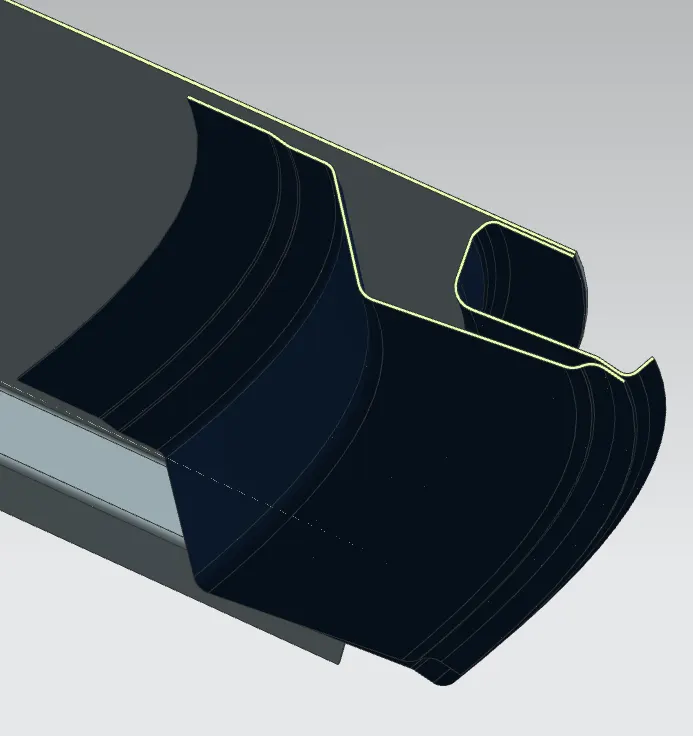
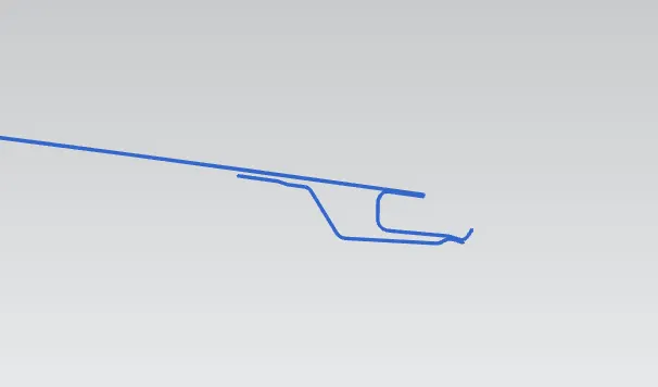
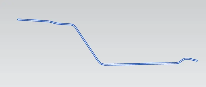
All Roofs
Final Assembly
Reinforcements:
Analysis :-
1. Bow Roof Prediction Formula:
W = [1.73 x 10^(-3) x L] + [1.85 x 10^(-8) x (R^2)/t] + [ 1.10x10^(-3) x l] - 2.68
Judgement Condition : OK< 2.7> 3.1
Where
L = Roof Length in X-Direction[mm](Roof dimension in 0-Y)
R = Roof curvature
R = 2(Rx*Ry)/(Rx+Ry)
Rx = X curvature
Ry = Y curvature
t = Roof plate thickness [mm]
l = Bow Roof Span [mm]
| S.No | BOW'S | Rx | Ry | R | I | L | t | W | OK/NG |
| 1 | FR & Bow 1 | 3293.87 | 2525.4 | 2858.894 | 349.26 | 2042 | 0.75 | 1.438454 | OK |
| 2 | Bow 1 & CR | 4807.1 | 3993.69 | 4362.805 | 485.4 | 2042 | 0.75 | 1.856107 | OK |
| 3 | CR & Bow 2 | 3996.47 | 3490.87 | 3726.599 | 409.66 | 2042 | 0.75 | 1.645845 | OK |
| 4 | Bow 2 & RR | 3399.71 | 2943.6 | 3155.257 | 325.8 | 2042 | 0.75 | 1.456613 | OK |
2. Snow Load Condition:
Qr = [Iy x t2] / [α x s x [(Rx + Ry)/2]2 x 10-8]
Note: The Qr value given over here is correct. There was a typo error in the formula given in the video.
Where
α = My x Lx2 x 10-12 , My = Y(Ly-Y)
Judgement condition = Qr ≥ 3.1
250 ≤ s ≤ 380
t = Roof plate thickness [mm]
Ly = Distance between the front and rear roof Rails on the Vehicle along with 0Y[mm]
Length of Roof panel with the center point between Roof rail Front /Rear as the front and rear reference point.
Lx = Distance between the Left and Right end of the roof on the Roof BOW [mm]
Width of the roof panel exposed on the surface.
Y = Distance front Front Roof Rail to Roof BOW[mm]
s = Distance for which Roof BOW bears divided load [mm]
s = L1/2 + L2/2
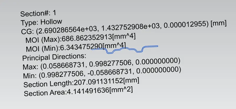
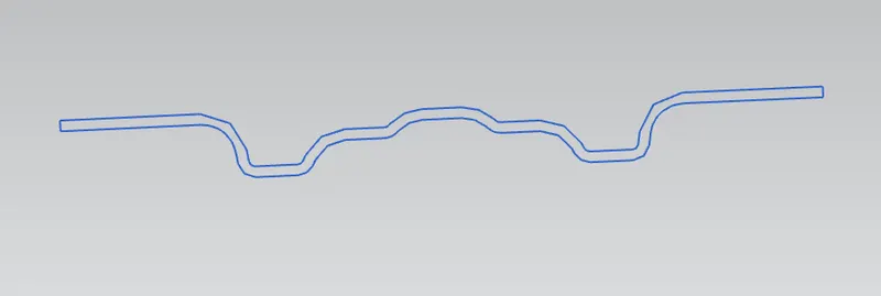
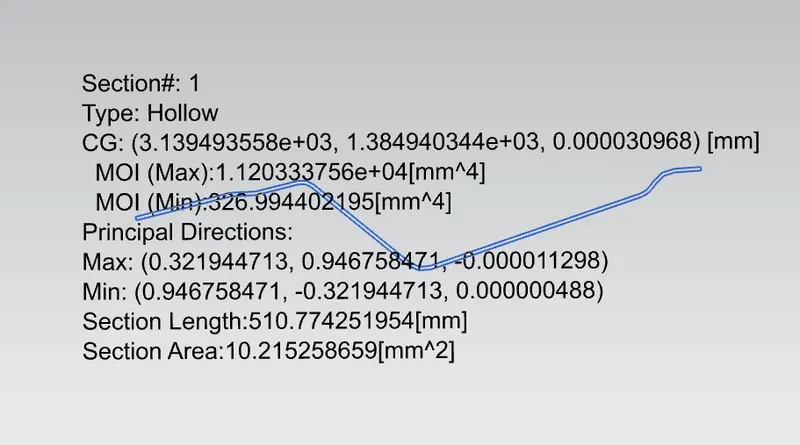
Iy = Geometrical moment of inertia of Roof BOW (Y cross-section )[mm4]
Rx = Lateral direction curvature radius of roof panel Y cross-section on Roof BOW [mm]
Roof panel curvature Radius of the Length Lx in Front view
Ry = Longitudinal Direction curvature radius of the Roof panel X cross-section on Roof BOW [mm]
Roof panel X curvature radius of length s in Side view
| S.No | Bow's | ly | a | My | Lx | Ly | Y | S | Rx | Ry | t | Qr | OK/NG |
| 1 | FR & 1st | 3,408.65 | 1.055597 | 746203 | 1189.38 | 2052 | 472.4 | 516.15 | 3,335.13 | 2,726.94 | 0.75 | 38.28 | OK |
| 2 | 1st & CR | 5,240.91 | 0.981402 | 835426.8 | 1083.85 | 2052 | 559.9 | 521.05 | 5,655.22 | 6,362.03 | 0.75 | 53.91 | OK |
| 3 | CR & 2nd | 1,757.74 | 0.818347 | 756957.6 | 1039.76 | 2052 | 482.2 | 459.35 | 4,331.37 | 11,675.18 | 0.75 | 13.8 | OK |
| 4 | 2nd & RR | 0.777282 | 705165.8 | 1049.89 | 2052 | 436.5 | 0 | 3585.48 | 16,724.39 | 0.75 | OK |
Conclusion:
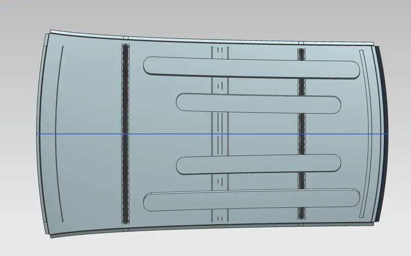
The roof areas along with the Bow's are designed witht the ditch area.
Two analysis were performed, namely bow roof prediction and the snow load prediction. Heat distortion is also determined, this every action has been performed.