Roof challenge
ROOF DESIGN
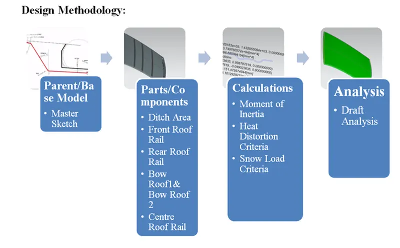
Aim: - To design the complect roof from styling to a complected roof with bow roof, front and rear panel, center roof with reinforcement for roof strength and perform draft analysis, inertia, load calculation.
Objective: -
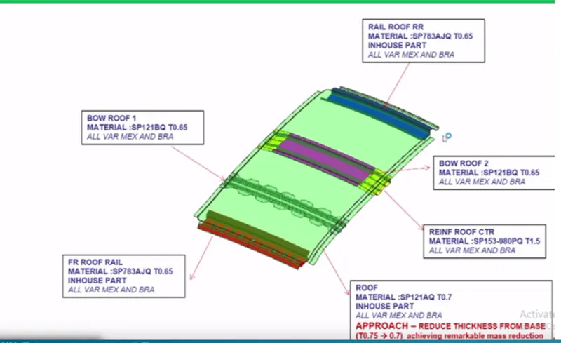
- The main objectives of this project are to design car roof with essential flanges, reinforcement like, Roof outer panel, Front roof rail, Back roof rail, bow roof 1and bow roof 2, and center roof with reinforcement to styling the surface by following the engineering standards.
- Perform a curvature study of the roof and perform the heat distortion and snow load criteria to determine the weather the bow roof is at correct position.
- Calculating the moment of inertia and section modulus for bow roof, center roof and front and back roof rail.
- Perform the draft analysis of each reinforcement.
Introduction: -
The roof is an important component in automotive BIW structure where it helps passenger to protect from external factors while in traveling such as harsh climatic conditions such as rain, sun and snow. It also acts as a cross member between body sides of the car body and provides provisions for front windshields, backdoor (in case of hatchback vehicles). Roof assembly also one among the parts which provide safety for rollover accidents.
An automobile roof or car top is the portion of an automobile that sits above the passenger compartment, protecting the vehicle occupants from sun, wind, rain, and other external elements. Convertible roofs, Roof modules, Roof modules,Hardtops, Sunroofs, tops, Targa tops, Vinyl roofs are the different variants in an Automobile.Some roofs have a window on them and are called sunroofs, while convertibles have special mechanisms that allow the roof to be retracted and be stowed away through a wide array of methods depending on the design.The roof of the car is made up of multiple parts that provide support and strength to the roof component. The actual roof sheet and the roof rails support the roof sheet. There are3 primary roof rails in a car the front, the center, and the rear, while additional roof rails are called Bow roof rails. The number of bow roof rails depends on the size of the roof. Headroom, visibility criteria, and target region also play a key role in roof design.
Design consideration of Roof
- Visibility criteria
- Curvature study
- Heat distortion and snow load criteria
- Draft analysis
- Safety parameters
- Head clearance
- The roof is made from a sheet of at least 0.75mm. This protects the cabin from external conditions and objects. The ditch areas are spot welded to the pillars of the car and certain areas of the roof rails, welding on the upper surface is avoided in order to maintain a good aesthetic.
- The front roof rail is made from a sheet of at least 1.25mm thickness. This part acts as a support for the roof sheet on the front it also provides a mounting area for the windshield. It is designed with support requirements, visibility criteria, and headroom space in mind. The roof is fixed to the roof rails with the use of mastics while the ends are spot welded.
- The Rear roof rail is used to provide strength to the roof panel front and it also acts as a link between windshield glass, roof panel, and headliner (interior trim).
- The bow roof rails provide additional support to the roof and are at least 1mm thick, they are positioned in such a way that they provide maximum support to the roof, Care must be taken so that they do not intrude into the headroom requirements of the car. Bow roof rails are an optional feature provided as required by the design. Small cars may have none while large ones may have 3 or more, they may also be integrated into the center roof rail in some cases. The roof is fixed to the roof rails with the use of mastics while the ends are spot welded.
- This is the roof rail that runs between the B pillar of the car and provides support to the center of the roof sheet they are usually 1- 2mm thick and also provide a support area for the center cabin light mount. The roof is fixed to the roof rails with the use of mastics while the ends are spot welded.
- Central roof rail helps in providing effectively support to the flat area of the roof as it is more susceptible to failure under the action of load. generally central roof rail is placed at the center of the roof which is connected to the B-pillar support structure. This central roof rail helps in adding the strength to the roof during the roll- over test. The thickness of the central roof rail is 1.25 mm.
Class A surface –
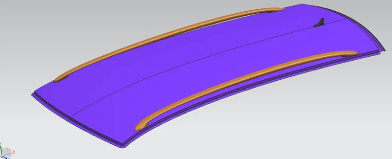
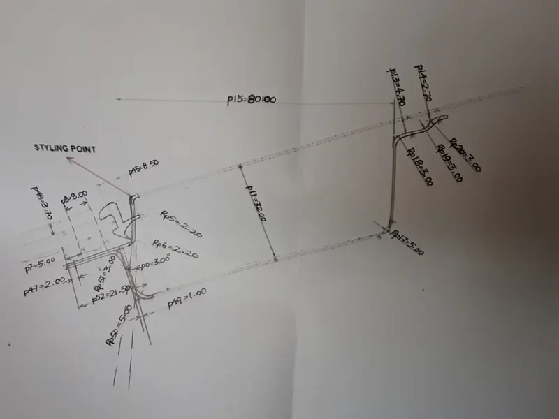
As a raw data a car roof is given as a styling from a class A team as below.
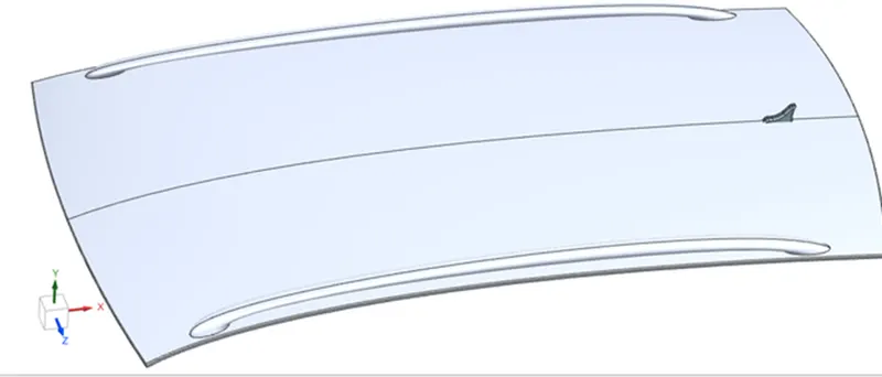
Master Sketch
Front Roof Rail reference images
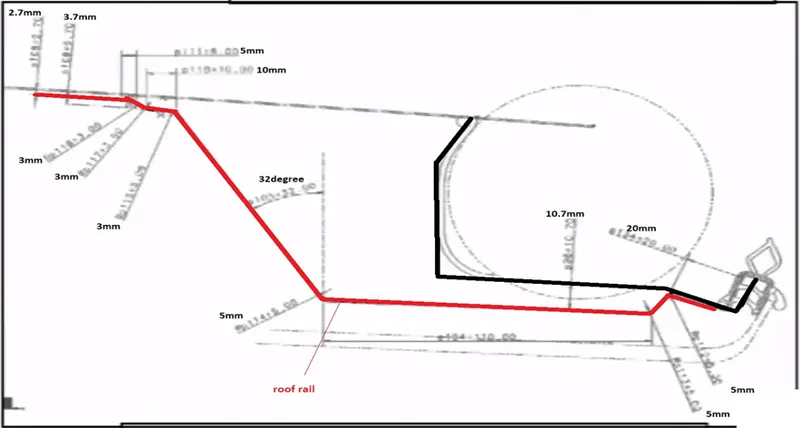
Rear roof rail master section reference image
The Commands Are used while Designing
Offset surface- The offset surface gadget makes a copy of the picked surface at a provided distance and guidance.
Offset Curve in Face- Offsets curve along the selected face. Offset adopts surface even if the surface blended or face has sharp corners.
Intersection Curve- Create intersection curve between two sheets of object.
Studio Surface- Create a surface any number of section and guide string.
Trim sheet- The trim sheet gadget parts the target surface along the intersection curve of the target surface and the gadget surface. The piece of the surface on either side of the intersection can be either discarded or retained according to need.
Law Extensions- Creates an extended surface subject to an open chain contour or a shut contour on the picked target surface. A draft can be obliged by the extension
Face blend- Creates a curved blend or fillet along two picked surfaces in gave direction vector. The curve of the blend can be changed regarding reach, width, and continuity
Extend sheet- Creates an extension of picked sheet up to a given distance
Offset in the face- Creates an offset in the face or edge on the target face up to a to a provided distance
Bridge curve- Create a roundabout portion between two intersecting and non-intersecting curves. The beginning and end point of the roundabout changed by providing distanced.
Projected curve- Creates a projection of curved profile onto a goal surface. The surface can be linear and curved. The direction can be changed by reasonable vector.
Sew- combines sheet bodies by using sewing common edges together, or combines solid bodies using sewing faces. Any opening between the surfaces can be closed.
Mirror Geometry- Mirror a geometry along a face.
Thicken- creates a strong body using thicken.
Designing the Reinforcement-
Roof Outer Panel/ Ditch Area-
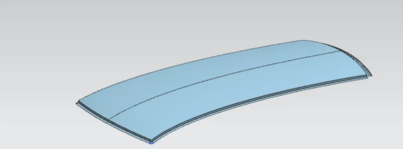
The Ditch Area of the Roof was designed by taking the considerations provided by the styling teams.
The ditch area was designed to have only 3 degree of maximum draft angle and 0.75mm thickness.
- The ditch area is the extended portion of the main roof concealed by other BIW panels.
- The rails of the roof were attached by using Spot welds and Mastic Sealants.
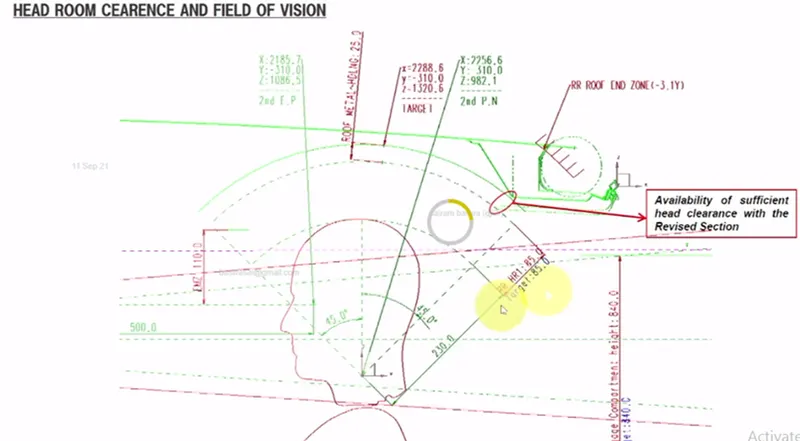
- Visibility Criteria, Head Room Clearance, windshield clearance and back door clearance was also taken into the design consideration of the Roof.
-
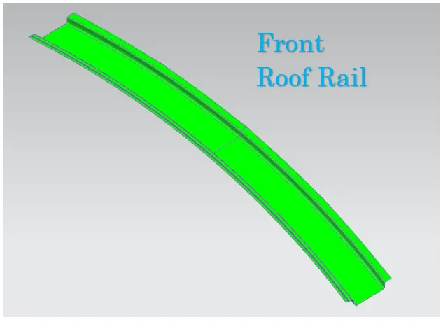
Front Roof Rail
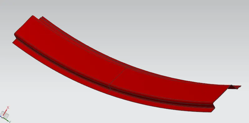
The front roof rails will be joining the wind shield, Body Side Inner and Outer panel, so the front roofs must be designed to have the visibility clearance for the Wind Shield.
- By considering the Deep Drawing of the part the front roof was designed to have the draft value of more than 5 degree.
- The front roof rail has the same offset surface for the ditch area where both will be connected using Spot Welds.
- The front roof rail was provided with embosses to increase the strength and stiffness of the rail.
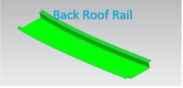
Rear Roof Rail
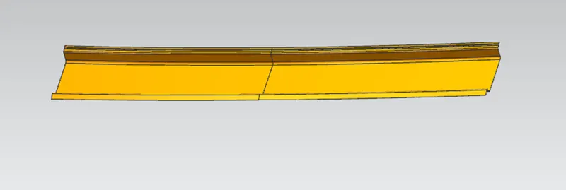
The Rear Roof Rail was designed by taking the back door clearance into consideration since the opening and closing of the back door will affect on the roof.
- The ditch area on the roof was connected with the rear roof by using the mastic sealant or spot welding.
- Spot welding will be used for joining the hinges of the Back Door with the Roof.
- Embosses were added to increase the stiffness and strength of the rail without affecting the head room clearance.
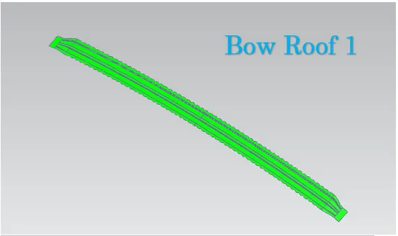
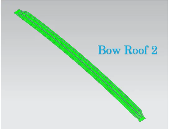
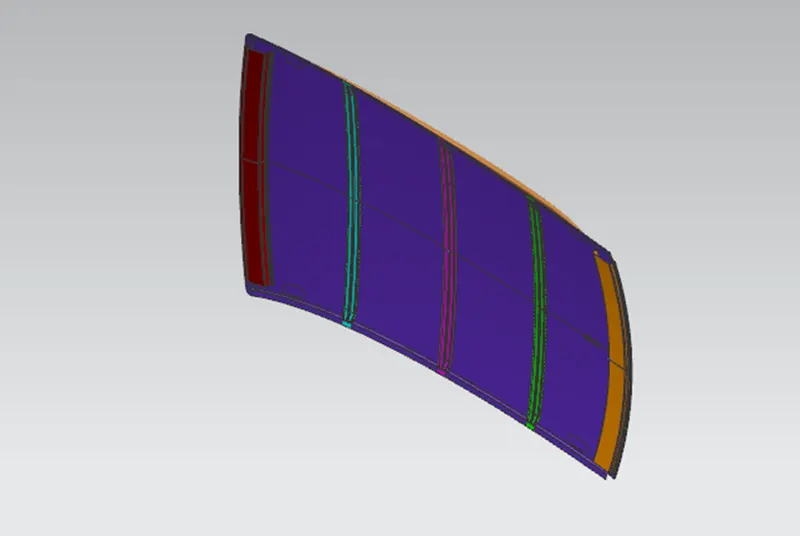
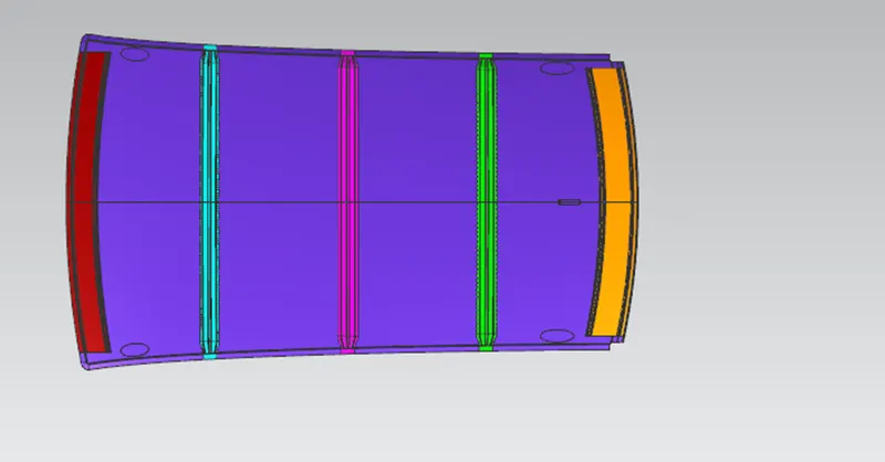
Bow Roof 1 &2
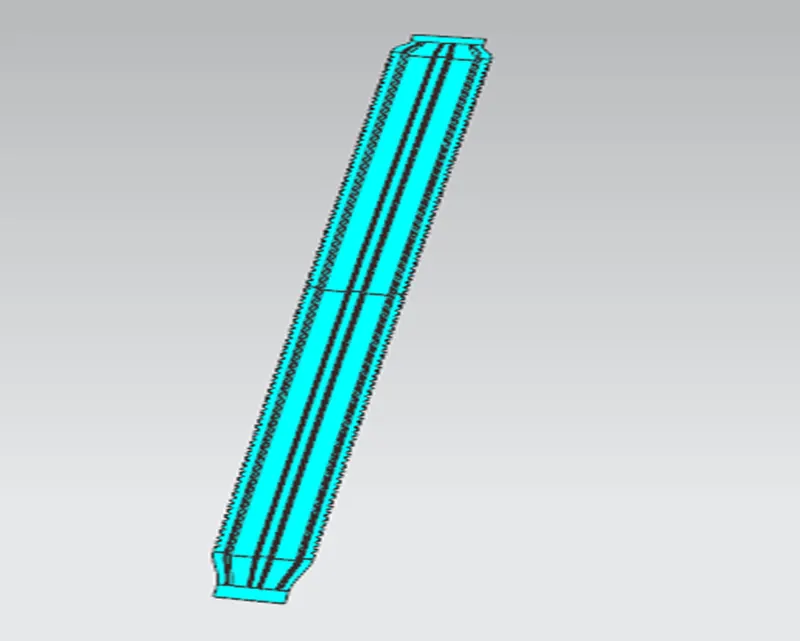
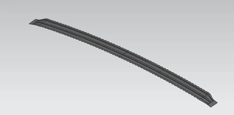
All the bow roof rails were placed between the front and rear roof rails.
- Bow roof rails were added to increase the stiffness of the roof since it has the large flat surface.
- To increase the curvature result of the roof where it needs to withstand the heat distortion and snow load criteria the bow roofs were positioned as per the standards.
- The bow roofs were provided with mastic points since the joining process will be done using the mastic sealants.
- Spot welds also possible but it will damage the aesthetic appearance of the car roof. Reinforcement was also provided all over the bow roofs to increase the stiffness rapidly.
- The bow roof position needs to satisfy the head room clearance and draft analysis for Deep Drawing.
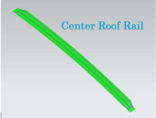
Center Roof Rail with Reinforcement
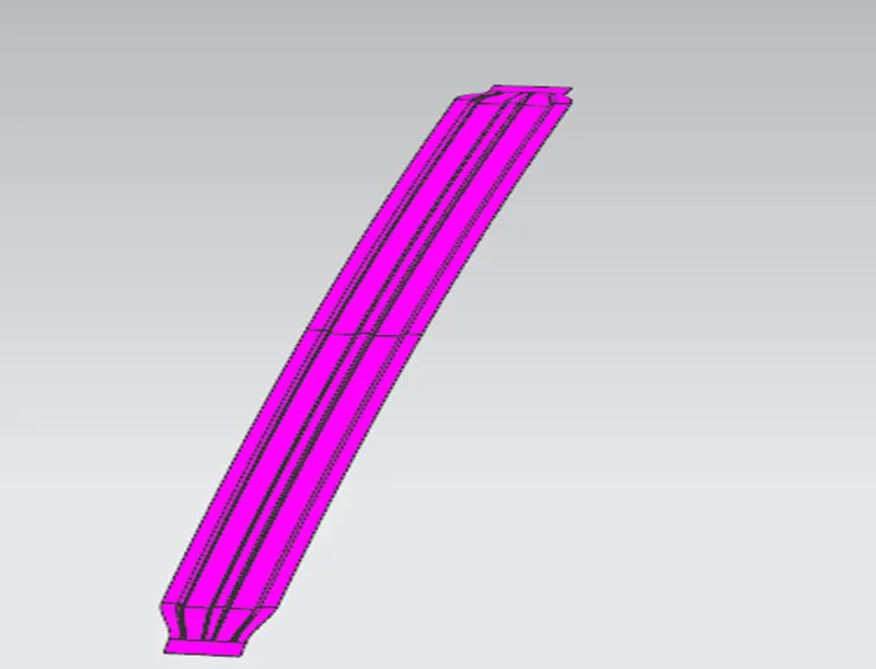
Center roof rail was place after the Bow Roof 1 in my model but it can also be swapped between the Bow Roofs but it should be positioned as center of the roof as much as possible.
- The center roof rail was designed to have a reinforcement roof rail which helps the roof of a car to increase the efficiency in curvature study.
- For creating the Mastic Points and Embosses on the Center Roof Rail again the Head room clearance must be taken into account.
- The reinforcement provided will increase the Geometric MOI of the part drastically.
Roof Crush Test
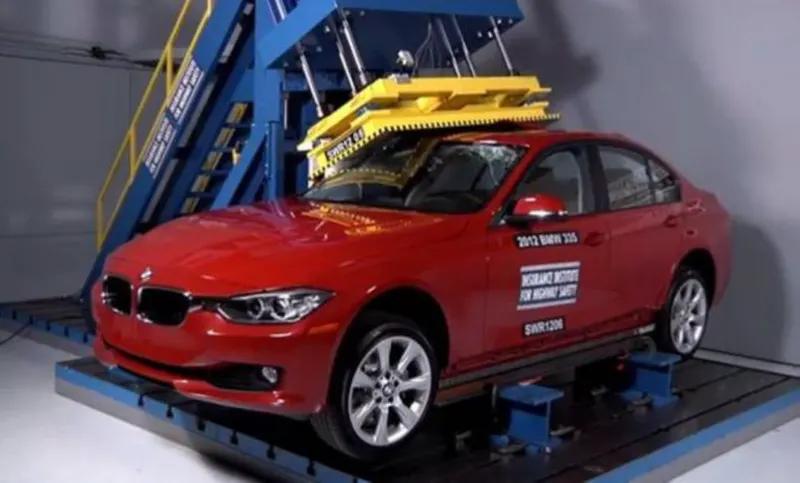
Roof crush test is the design given by the IIHS (insurance institute of highway safety).
After analyzing the many accidents IIHS has then fixed some regulations, that how to perform the crush test.
IIHS gives the rating based up on this test. For this they consider two points while giving the rating How fast the car can reform to its original shape after the roll over and how deep is the protrusion after the roll over.
CONDITIONS TO FOLLOW FOR ROOF CRUSH TEST:
There are two conditions that should be followed for the roof crush test, they are
INITIAL CONDITION:
- Close and lock all the doors
- Close all the windows
SECOND CONDITION:
Fix the body sill or chassis frame on a hard lever surface horizontally.
METHOD OF APPLYING THE FORCE:
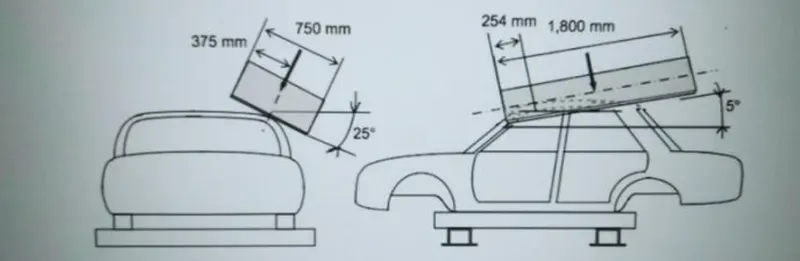
The load is applied in such a way that 5 is tilted from the front end to the rear end and the load will be in 1800 mm in length and 750 mm in width. The load is applied at the position of 25 from the flatness of the roof. The load is applied on the roof for almost 120 sec and the crush speed at which the load applied is 13 mm/sec or less than that.
RESULTS:
If the displacements go above the requirements level, then we have to increase the bow roof thickness or add more mastics points to increase the strength. the stronger the roof the better it can protect the occupants in the roll over crashes.
Draft Analysis
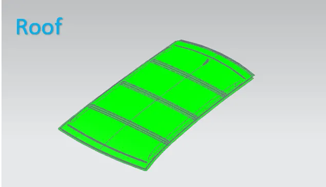
The Draft Analysis command enables you to detect if the part you drafted will be easily removed. This type of analysis is performed based on color ranges identifying zones on the analyzed element where the deviation from the draft direction at any point, corresponds to specified values.
Image of draft Analysis
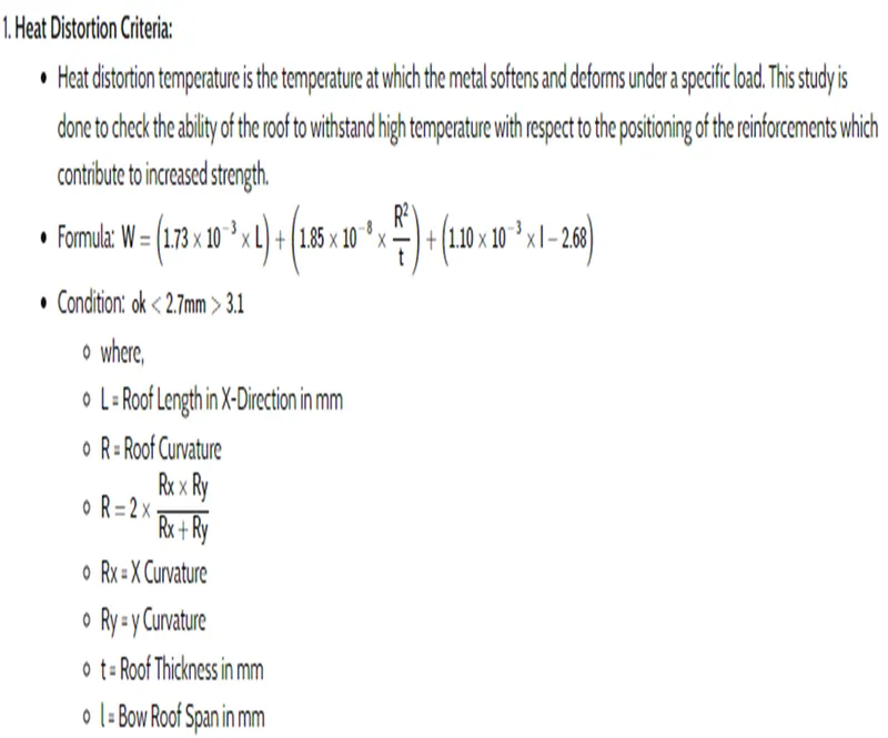
HEAT DISTORTION CRITERIA:
Heat Distortion is the temperature at which the metal softens and deforms under a specific load. This study is done to check the ability of the roof to withstand high temperature with respect to the positioning of the reinforcements which contributes to increase the strength.
CALCULATION TABLE:
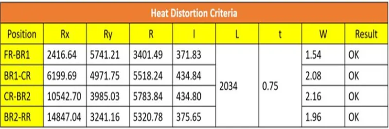
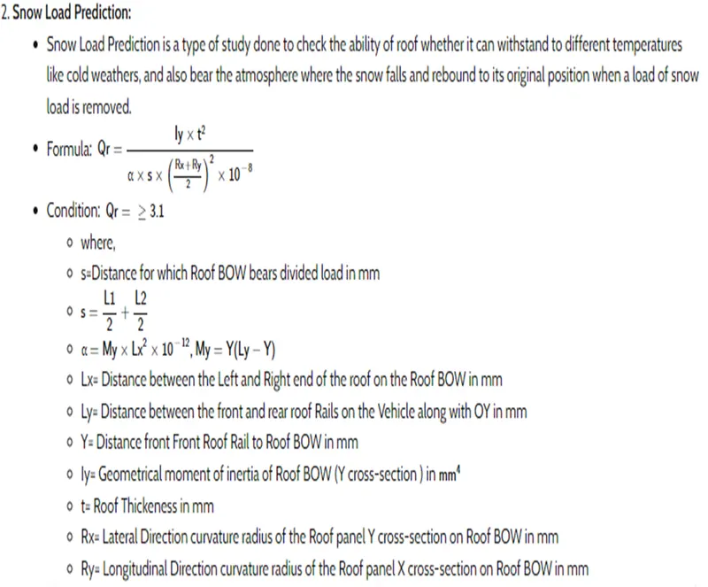

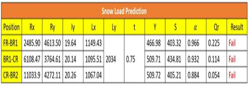
From the above result above value doesn’t consider the snow load criteria. So, we need to make roof stronger create embosses.
Section Modulus –
Bow roof 1
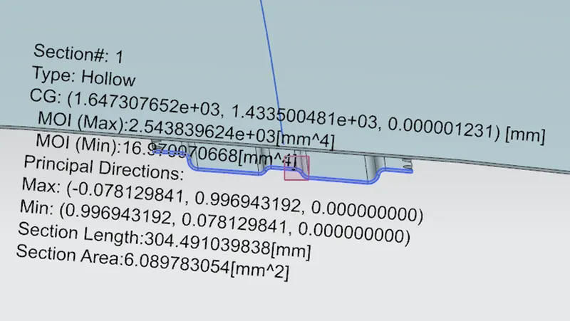
S=I/Y
= (2.543 X 10^3) / 34.82
=73.03mm^2
Bow roof2
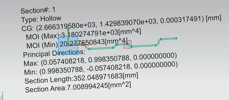
S=I/Y
= (3.123 X 10^3)/37.50
= 83.28mm^2
Center Roof
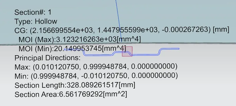
S=I/Y
= (3.123 X 10^3)/37.50
= 83.28mm^2
Curvature study
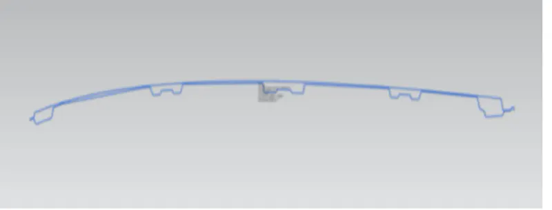
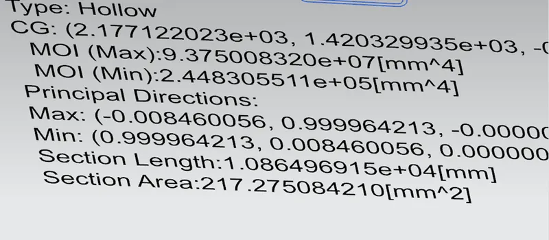
Front Roof Rail
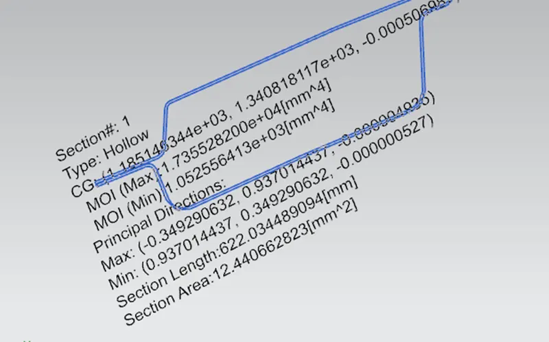
S=I/Y
= (1.735 X 10^4) / 61.82
=280.65mm^3
Back Roof Rail Section modulus
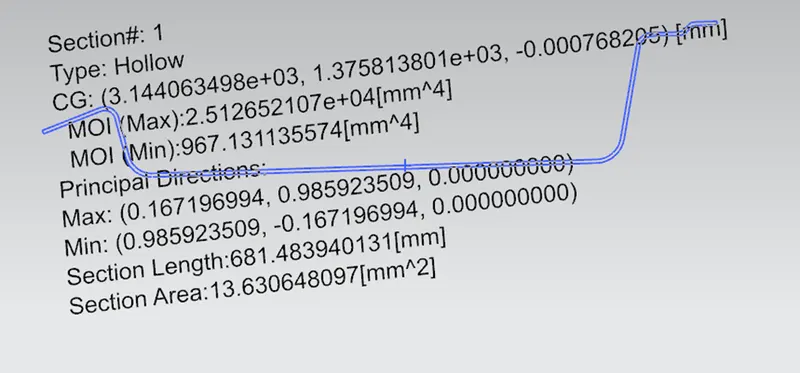
S=I/Y
Y=70.33
S= (2.512 X 10^4)/70.33
=357.17mm^3
Design View
Isometric view
Front View
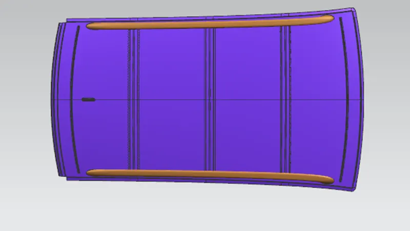
Back View
Conclusion- For the Given Roof styling, the essential flanges and reinforcements were developed and checked for Draft analysis. The curvature study and Section Modulus on the roof was carried out and to determine the position of the Bow-roof the Heat Distortion calculations were also performed. Thus, the BIW roof of a car was designed and achieved a better result of snow load by applying embosses over the roof.