Fender Design - Wheel Arch Challenge
FENDER DESIGN – WHEEL ARCH
AIM
The objective of this challenge is to find whether the given fender design satisfieS with the given wheel arch standards.
THEORY
Wheel arch is the semi-circular fender area above the wheel. There are different standards for different regions in order to design a good fender wheel arch area. The most common standards used for studying are Japan, European and U.S. standards. All these standard criteria are derived based on the conditions of the road in those regions.
1.) Japan standards
From the centre of the wheel a 90 degree line is made and a 30 degree rearward and a 50 degree forward lines are made and clearance value L is measured at all these three positions and a minimum of 5mm should be maintained and for wheel guard the value a at 30 and 50 degree is to be calculated and a minimum value of 5mm has to be maintained.
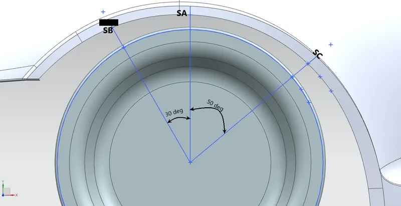
2.) European standards
For European standards additional to the three lines we seen in the Japan standards a 150mm offset is made from the horizontal line at the centre and to where it touches the fender a line is made from the wheel centre. Now midpoint between the 50 degree line’s intersection point with fender and 150mm line’s intersection point with fender is taken and a line is made from wheel center. Now, the clearance value L is calculated at these 5 positions and a clearance check table is made and minimum should be 10mm and for wheel guard the same procedure as in Japan requirement.
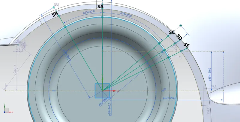
3.) U.S. standards
For U.S. the clearance value L has to be measured at every 10 degree from -20 degree to 180 degree and clearance check table has to be made and all the values has to be more than 5mm to satisfy the regulations and for wheel guard requirement the same regulation for the Japanese system is followed.
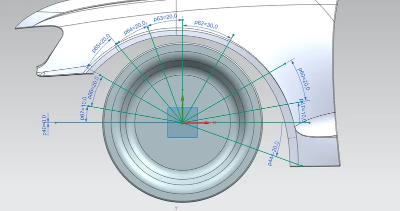
PROCEDURE
For this challenge we use European standards to evaluate the given fender wheel arch area.
- We create a datum plane in the outmost portion of the wheel surface.
- Now we make a sketch in this plane and create a vertical line from the wheel center
- 30 degree rearward from vertical and 50 degree forward from vertical lines are made passing through the wheel center.
- Now, the horizontal line through wheel center is offset by 150mm in positive y direction and the point where it meets with the fender edge is taken and a line is drawn from this point to the wheel centre.
- The outer edge of the fender towards the wheel is projected into sketch and the intersection points with all these four lines are made namely B, A, C, E. For point D the midpoint between the points C and E along the projected edge is taken and a line is drawn from point D to wheel centre
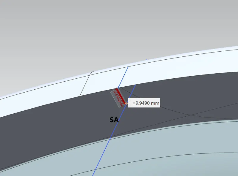
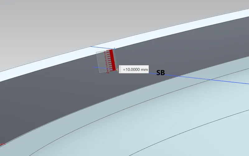
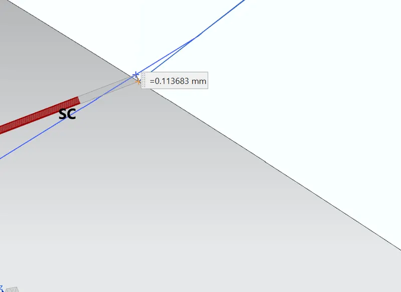
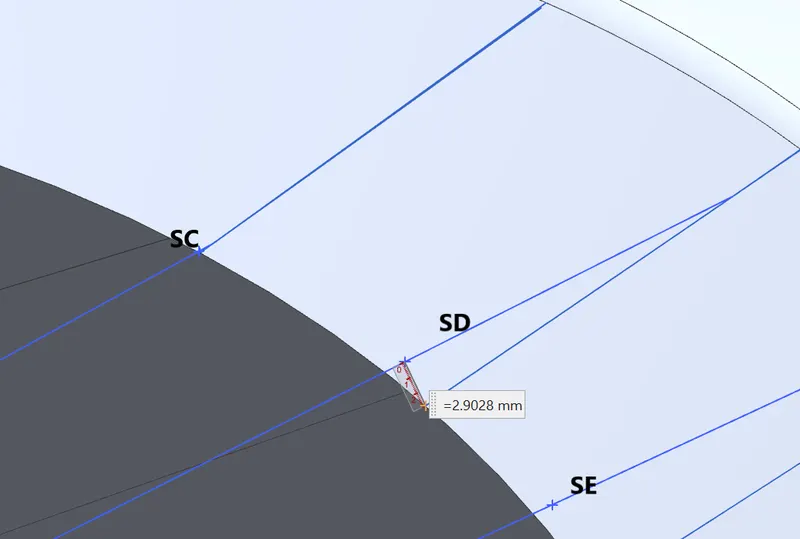
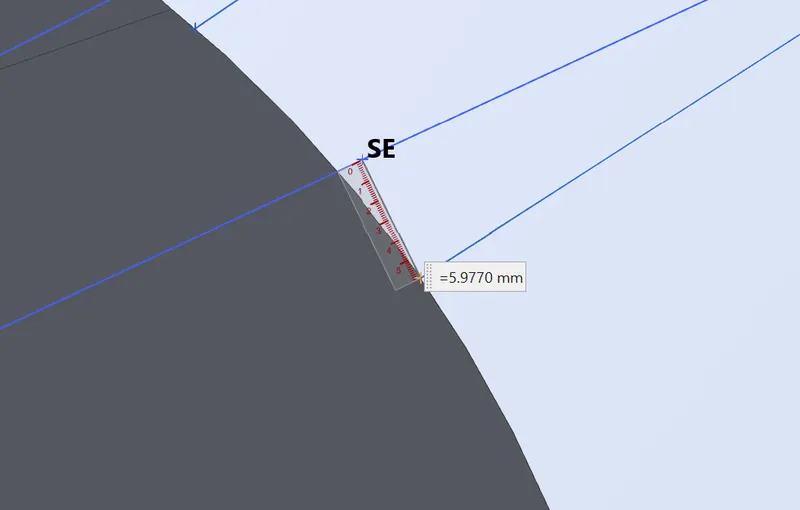
- Now, we have all the five lines this sketch is projected onto the face edge and the intersection points are taken on the face edge and with all the points the clearance values 'L' and wheel guard clearance values 'a' are measured and tabulated into clearance check table given in the observations.
OBSERVATIONS
Table for clearance 'L' check
|
Sections |
Measured 'L' value (mm) |
Result |
|
SA |
9.9490 |
<10 ----> FAIL |
|
SB |
10.000 |
=10 ----> PASS |
|
SC |
-0.113683 |
<10 ----> FAIL |
|
SD |
-2.9028 |
<10 ----> FAIL |
|
SE |
-5.9770 |
<10 ----> FAIL |
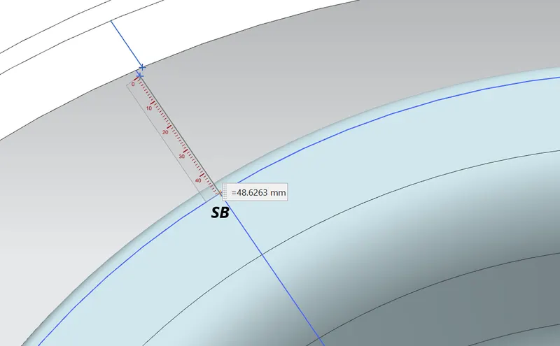
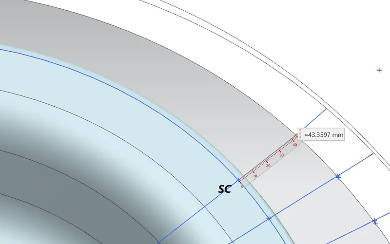
Table for wheel guard clearance 'a' check
|
Sections |
Measured 'a' value (mm) |
Result |
|
SB |
48.6263 |
>5 ----> PASS |
|
SC |
43.3597 |
>5 ----> PASS |
CONCLUSION
From the results that we obtained we can conclude that the fender given to us doesn’t fit into the European standards for clearance L at points B, C, D, and E. So, we advice the styling team come up with a new design to meet the given minimum length condition for L at these points.