Roof challenge
ROOF PANEL REINFORMENTS
Objectives:
- To study about different attachments provided onto an automotive roof.
- To analyze the given roof surface data to design various reinforcements
- To generate and check different features for thier feasibility
- To analyze and value the critirias for heat distortion and snow load.
Introduction:
Roof is one of the largest structure in a vehicle. As we know, most types of the roof panels are large and lengthy planes which have a small curvature. Curvature of the roof results in increasing the strength of the planar outer surface, However, for automotive applications, we need to make many structural components and reinforments to attach the outer panel into the car bIW and to strengthen the roof.
Roof may undergo loading conditions or stuctural vibrations during the different applications. so it is important to pass the requirement regulation criterias to ensure the strength of roof. Also the entities for front windsheild and rear door will be installed onto the inner stucture of a roof.
In this project, i will be generating all the required components of a roof inner panel using the given master sections. and later it will be analyzed for various criterias to check feasibility.
Design methodology:-
Outer panel of the roof which is the styling data is given. we need to extract the outer surface for generating inner panel.
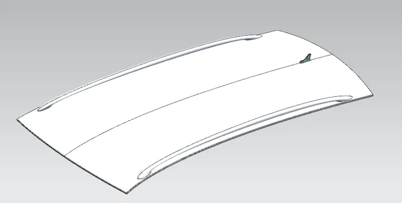
Since roof is a symmetrical section, we only need to make half of the datas. Others will be mirrored about axis passing through the center (X axis) and sewed to form single entity.
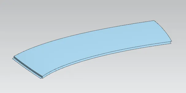
To attach the outer panel into the BIW, we have to make the necessary flanges at edges.
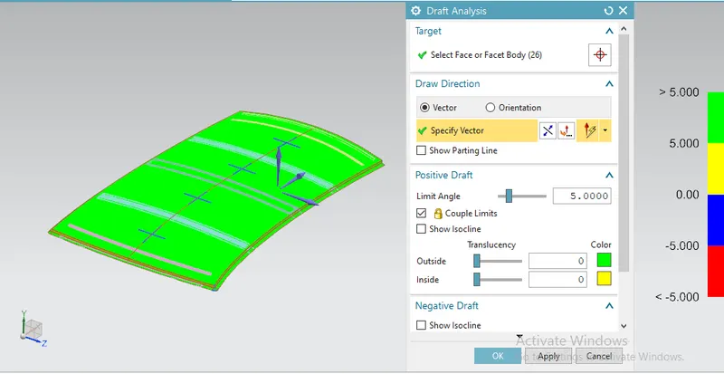
Outer panel will be tested for practicality using draft analysis.
Draft analysis result:
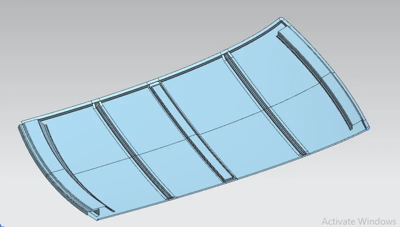
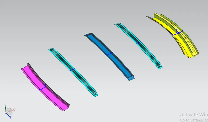
Various attachments provided for the inner panel are listed below:
- Front roof rail
- Rear roof rail
- Center roof rail
- bow roofs
Design guidelines:
- Inner panel components will not be directly joined with outer panel, There will include mastic seals between components and outer panel. so the gap is provided in the design.
- For the edge portions, it mostly include spot welding. inner panel components will have extended flanges which joins with the flange of outer panel.
- Part thickness for all components is generally given as 0.75 mm.
- The gap betwenn rails will be according to the heat distortion criterias. So the required modifications can be done after analysis.
1. Front roof rail:
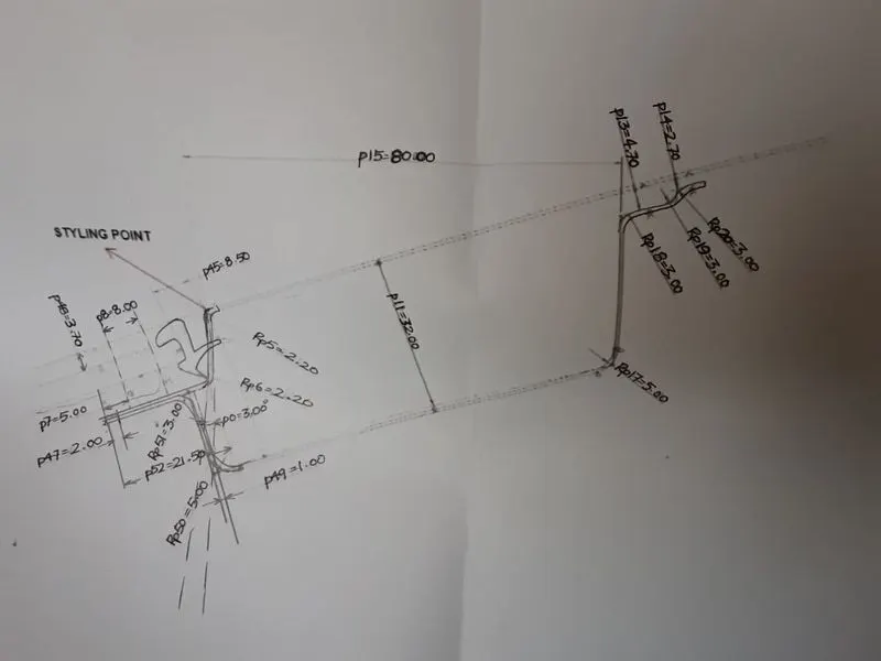
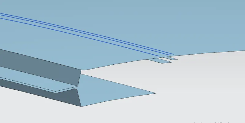
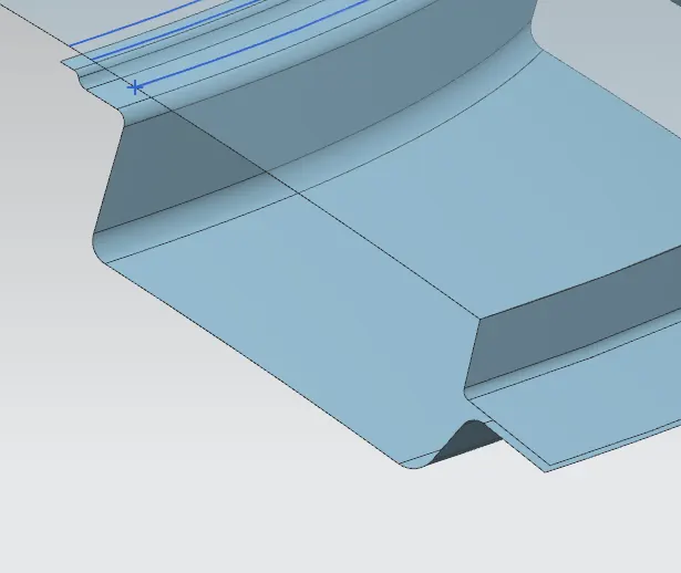
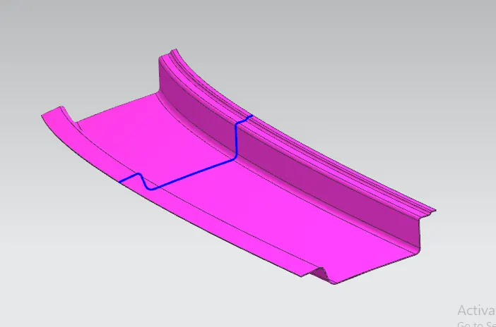
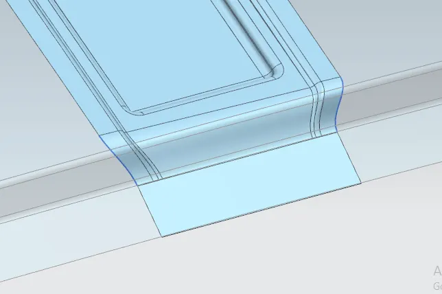
It will be the first attachment will be provided onto the inner panel. As the name signifies, it will be attached to the front portion. The design of the rail must be done by considering holding mechanism that joins with the windsheild glass. So the rail needs to stronger enough to carry windshield and roof joining sections.
Section data given:
Design model:
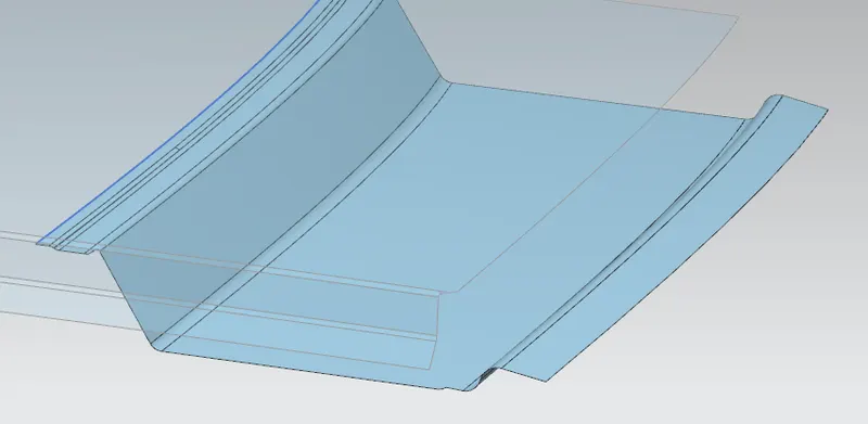
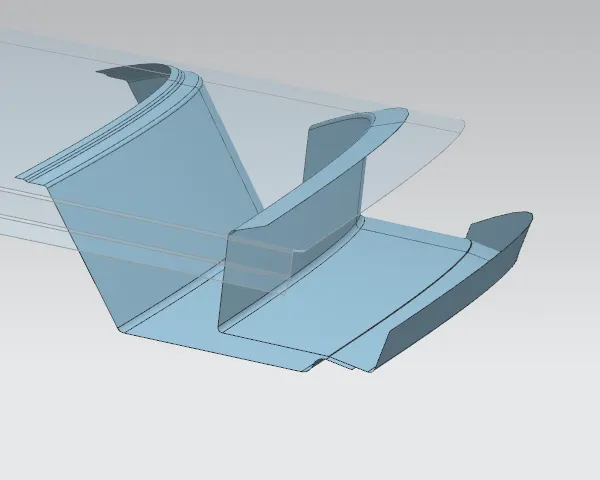
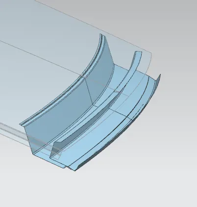
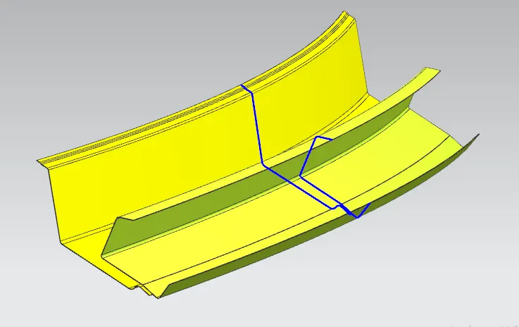
Rear roof rail:
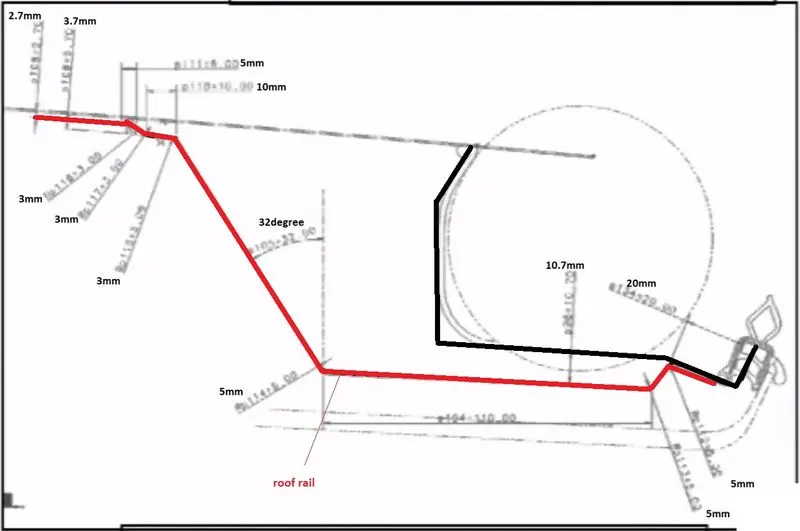
Construction of rear roof rail requires to consider the conditions for Rear head room clearance. A minimun clearance of 28 mm is required between the passenger head and rear roof rail. Also the mechanisms to attach the rear door will be installed to the rear roof rail.
For the design, we will provide a section that will be used by the rear door hinge. When opening and closing the rear door, the hinge part will come inside the rear roof rail. we will consider a circular provision for this mechanism avoiding collition with rail parts.
Master section:
Design:
Bow roofs:
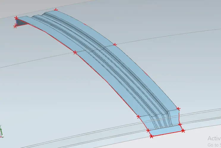
Bow roofs are structures with less width and a span length equal to the full width of the outer panel.
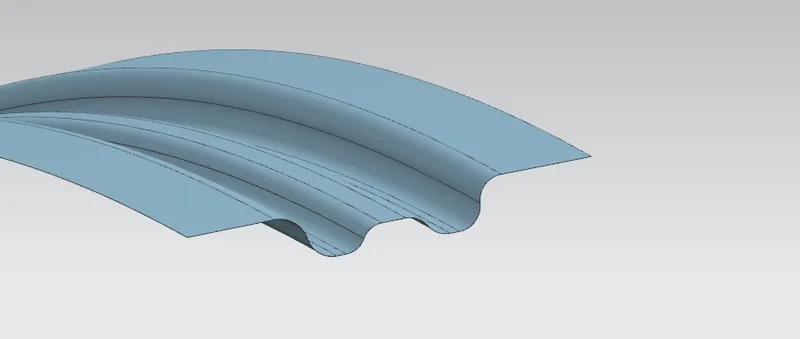
These are used to strengthen the roof panel. normally, 2 or more bow roofs will be in common vehicles. It is made up of the same sheet metal material, so for strengthening purpose, bow roof will have a wave type of section data.
Number of bow roof will depend upon the design, more can be added to withstand heavy loads according to the criterias.
Design of bow roof:
Center roof rail:
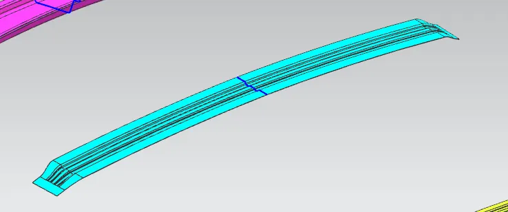
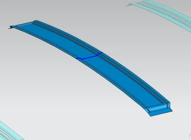
it is also a strengthening component whih is placed at almost the center of the roof length. center rail will have more width than bow roof. Center rail will be mounted on to the center pillar of the car, so the stress on roof will be transfered to the biw structure through center rail.
Embosses are added to the center rail for strengthening.
design:
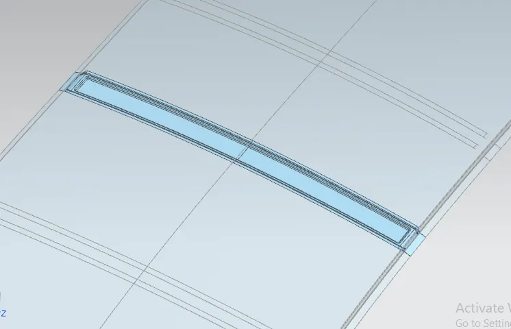
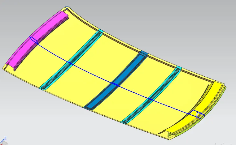
Final assembly:
ANALYSIS
Heat distribution criteria:
W = [1.73 x 10^(-3) x L] + [1.85 x 10^(-8) x (R^2)/t] + [ 1.10x10^(-3) x l] - 2.68
Judgement Condition : W< 2.7
Where
L = Roof Length in X-Direction[mm](Roof dimension in 0-Y)
R = Roof curvature
R = 2(Rx*Ry)/(Rx+Ry)
Rx = X curvature
Ry = Y curvature
t = Roof plate thickness [mm]
l = Bow Roof Span [mm]
Calculation table:
|
HEAT DISTORTION ANALYSIS |
||||||||
|
SECTION |
L |
Rx |
Ry |
R |
t |
I |
W |
RESULT |
|
FR - BOW 1 |
2032.25 |
5738.42 |
2307.79 |
3291.76 |
0.75 |
356.31 |
1.309 |
OK |
|
BOW1 - CR |
2032.25 |
4986.49 |
6100.49 |
5462.49 |
0.75 |
451.94 |
1.569 |
OK |
|
CR - BOW2 |
2032.25 |
4051.62 |
10174.80 |
5749.21 |
0.75 |
338.68 |
1.86 |
OK |
|
BOW2 - RR |
2032.25 |
3306.34 |
14370.79 |
5564.53 |
0.75 |
404.54 |
1.985 |
OK |
Snow Load test:
Qr = [Iy x t2] / [α x s x [(Rx + Ry)/2]2 x 10-8]
Where
α = My x Lx2 x 10-12 , My = Y(Ly-Y)
Judgement condition = Qr ≥ 3.1
t = Roof plate thickness [mm]
Ly = Distance between the front and rear roof Rails on the Vehicle along with 0Y[mm]
Length of Roof panel with the center point between Roof rail Front /Rear as the front and rear reference point.
Lx = Distance between the Left and Right end of the roof on the Roof BOW [mm]
Width of the roof panel exposed on the surface.
Y = Distance front Front Roof Rail to Roof BOW[mm]
s = Distance for which Roof BOW bears divided load [mm]
s = L1/2 + L2/2
Iy = Geometrical moment of inertia of Roof BOW (Y cross-section )[mm4]
Rx = Lateral direction curvature radius of roof panel Y cross-section on Roof BOW [mm]
Roof panel curvature Radius of the Length Lx in Front view
Ry = Longitudinal Direction curvature radius of the Roof panel X cross-section on Roof BOW [mm]
Roof panel X curvature radius of length s in Side view
Calculation table:
|
SNOW LOAD CALCULATION |
||||||||||||
|
SECTION |
Lx |
Ly |
Rx |
Ry |
Y |
t |
s |
L1 |
L2 |
a |
Qr |
RESULT |
|
FR - BOW 1 |
1186.77 |
1832.4 |
2388.44 |
4688.29 |
445 |
0.75 |
491 |
445 |
540 |
0.8695 |
19.28 |
OK |
|
BOW1 - CR |
1136.24 |
1832.4 |
6006.84 |
3760.69 |
540 |
0.75 |
480 |
540 |
420 |
0.801 |
11.24 |
OK |
|
CR - BOW2 |
1108.52 |
1832.4 |
4235.85 |
10593.55 |
420 |
0.75 |
485 |
420 |
550 |
0.729 |
10.49 |
OK |
|
BOW2 - RR |
1093.92 |
1832.4 |
4052.98 |
16117.42 |
550 |
0.75 |
- |
- |
- |
- |
- |
- |
Conclusion:
The design procedure for roof of an automotive is studied. Design experiment is conducted on the given roof outer panel, and all required commodities are generated.
Roof elements are analysed for heat distribution and snow load criteria. The produced entities succesfully passed the analysis fulfilling all requirements.