Roof challenge
GOAL:
The objective of this challenge is,
i) To study the roof curvature and place the bow roofs at respective positions.
ii)To create flanges on the roof also develop front and rear roof rails from the given roof styling.
ROOF:
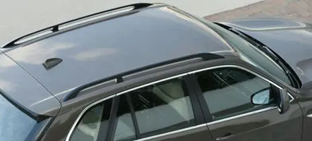
The car roof is the uppermost part of the vehicle.It acts as a weather shield and reduces damage to passengers on roof collisions.The following image shows car roof:
There are various types of car roof like convertible, roof with sun screen,roof with solar panel mounted.
THE ROOF MUST ABSORB THE COLLISION ENERGY WITHOUT HITTING THE OCCUPANT'S HEAD.
i)DESIGNING OF ROOF:
The roof should be designed in a way that it must pass the test recommended by safety regulation organisations.
1.Roof crush test: A constant appliction of load on the one corner of the roof and recording the maximum load that a roof can bear without colliding.The maximum load is Fmax.
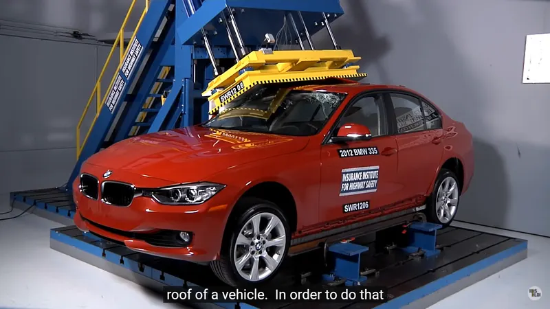
Fmax is divided by weight of the vehicle to get strength to weight ratio(swr).
`(Fmax)/(weight) = SWR`
The SWR should be equal to or greater than 4 in order to get good roof rating.
2.Heat distortion criteria: This is calculated using the given formula on the roof and the recommended value should between 2.7 to 3.5 and shouldn't cross 3.5. This is named as 'W'.
W = [1.73 x 10^(-3) x L] + [1.85 x 10^(-8) x (R^2)/t] + [ 1.10x10^(-3) x l] - 2.68
3.Snow load condition: Similar to heat distortion criteria it also calculated from a formula that can predict the snow load bearing strength.It is represented as Qr and it's value shouldn't be less than 3.1.
Qr = [Iy x t2] / [α x s x [(Rx + Ry)/2]2 x 10-8]
4.visibility criteria:This checked for the driver's visibility on the road after roof mounting. The roof front rail is designed ,that it never affects the visibility of the driver.
5.Head room clearance:There must be a clearance provided from the roof to prevent hitting of passenger's head on it.(since it depends on the passenger's height too).
and so on.. These many test are performed for one reason and it is to reduce the death and injuries to the vehicle occupant during rollover crash or roof collisions
Now-a-days automobile manufactures are preparing to install electronic stability control(ESC) in order to get more control over the vehicle and to prevent the rollover death .
DESIGNING OF ROOF in NX CAD:
Create the parts in seperate part file folder and assemble them together.
ROOF:
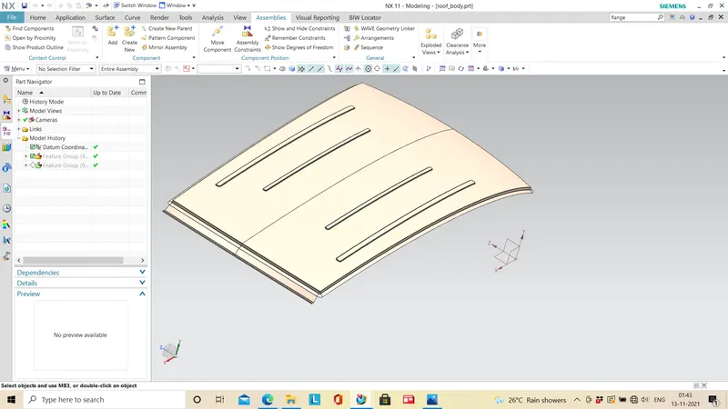
Skin data of the roof is given as input for roof designing.
Extract the face of roof (one half)enabling without holes option to remove the holes on the body face and perform the operation.
create flanges on front and rear side of the roof by following the master section.Mirror the geometry and join it.
Thicken the roof to get the solid roof body.make sure there is no sharp corners.
FRONT ROOF RAIL:
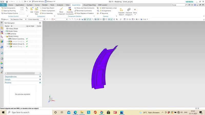
The front rail is situated in the leading edge of the roof.Front rail is designed by following the master section and sketch of the rail given in the question.
Offset the roof surface to 32mm to get the base of front roof rail.perform the necessary operations to get the required shape and dimensions.
SECTION VIEW:
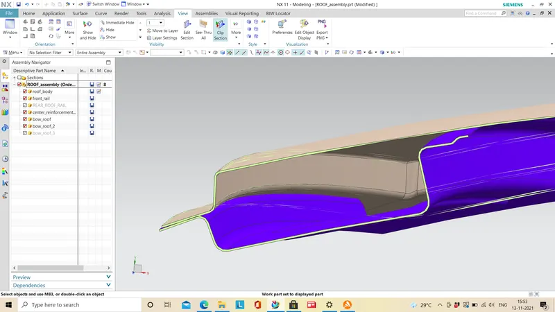
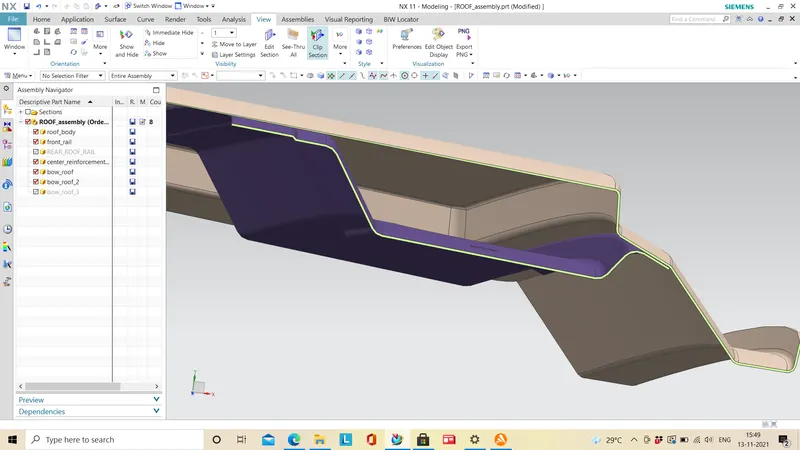
The section view of the image is taken at o-y region of the roof.
DRAFT ANALYSIS:
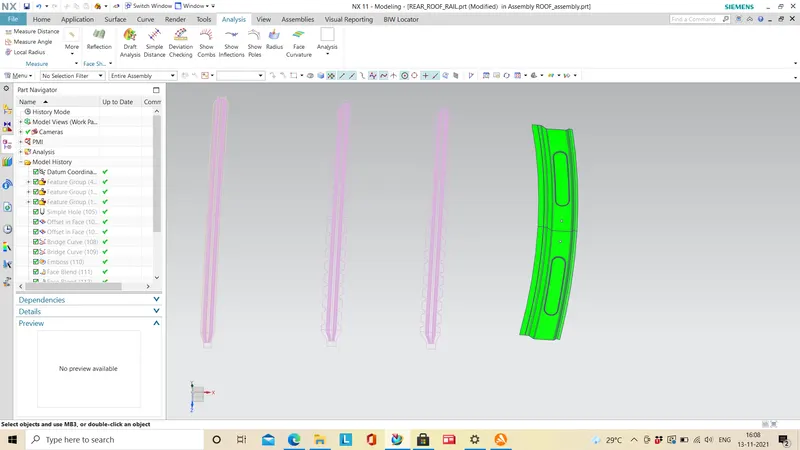
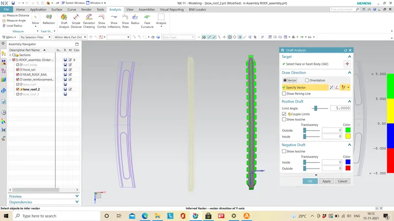
Draft angle is the measure of taper of molded or casting products from the parting line.It is essential for ease of produceability.The draft angle for analysing the roof rail is set to 5 deg.
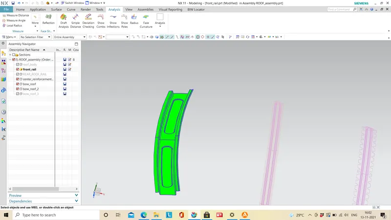
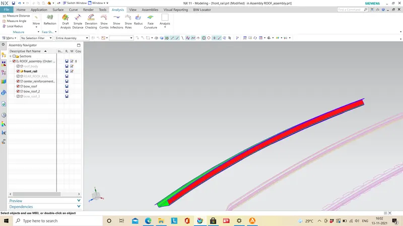
In draft analysis i found that one side of the rail is not drafted and it is indicated in red color since it is negative draft angle. Try to avoid these kind of errors.
SECTION INERTIA ANALYSIS:
`S = I/Y`
I - Moment of Inertia, whose unit is `mm^4`
Y - Distance from the neutral element to the end of the object.
Following the formula ,we can tell section modulus is the ratio of moment of inertia to the distance of end of the object from the neutral element.
It can also be defined as the measure of the strength of the given member.It is a shape property of the given cross section of given shaft section.
The unit of section modulus is `mm^3`
The value of section modulus is a reflection of the resistance to bending value.Hence to know the bending bearing capacity of a product it is convenient to calculate the section modulus.
More the section modulus value ,more the material is resistant to bending.
It is a measure of strength of the material.In a case , where beam is made up of two material finding the section modulus will help us to know the tougher material.
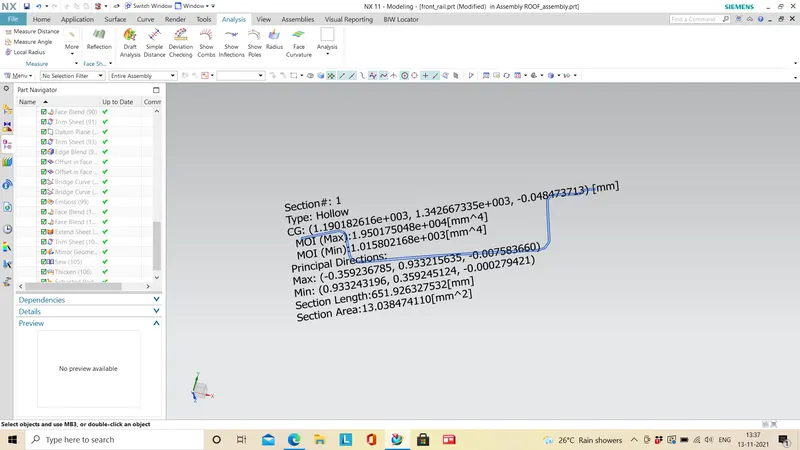
the moment of inertia is I = 19501 mm4 and Y = 72 mm. from the given formula, S = 270mm3
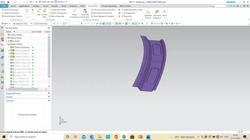
REAR ROOF RAIL:
SECTION VIEW:
DRAFT ANALYSIS:
SECTION INERTIA ANALYSIS:
This is the master section of rear roof rail and the result of section inertia analysis.
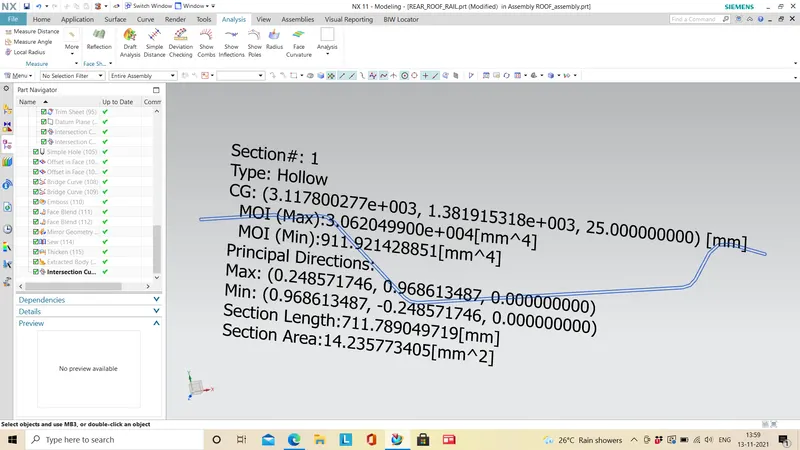
The moment of inertia is I =30620mm4 and Y = 159/2,Therefore S = 30620/(159/2) = 385 mm3.
BOW ROOF1& CENER REINFORCEMENT:
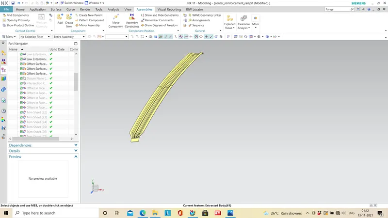
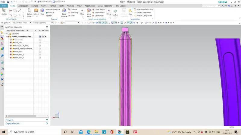
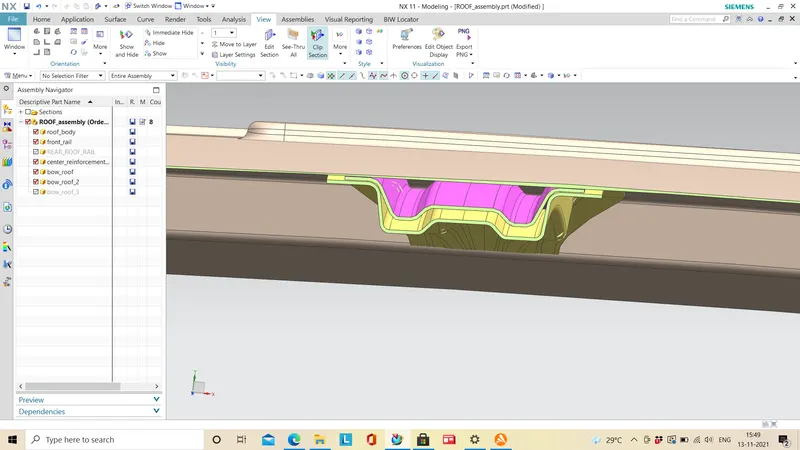
The center reinforcement and the bow roof1 is placed at same position of the roof.
SECTION VIEW:
DRAFT ANALYSIS:
SECTION INERTIA ANALYSIS:
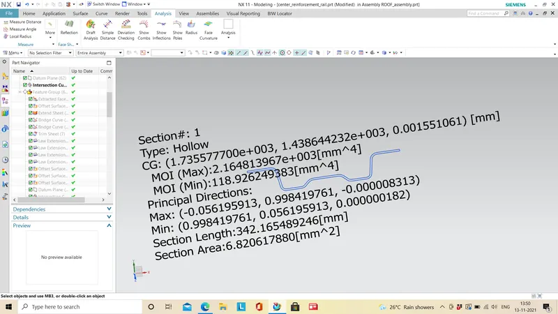
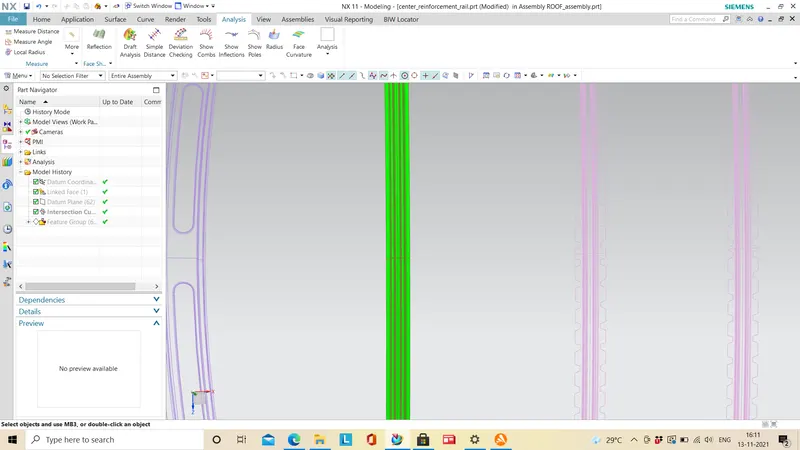
Moment of inertia for the center reinforcement is I=2164mm4 and Y=30,hence the S = 72.3mm3
BOW ROOF2:
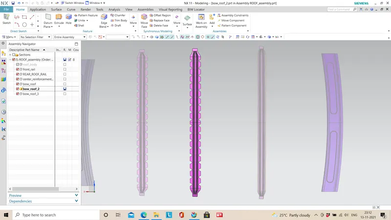
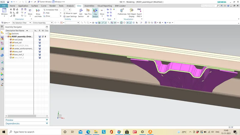
SECTION VIEW:
DRAFT ANALYSIS:
SECTION INERTIA ANALYSIS:
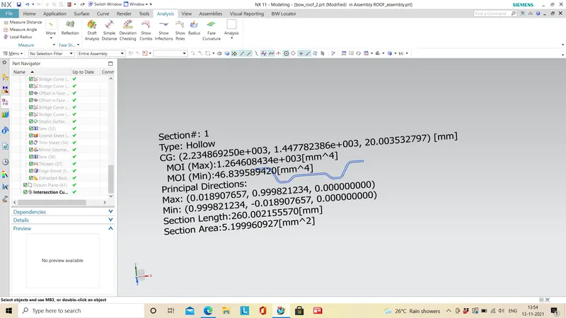
moment of inertia is I = 1264mm4 and Y = 26.5mm and then S = 47.95mm3
BOW ROOF3:
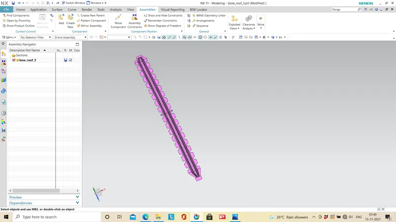
DRAFT ANALYSIS:
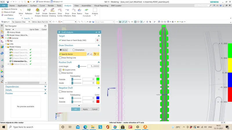
SECTION INERTIA ANALYSIS:
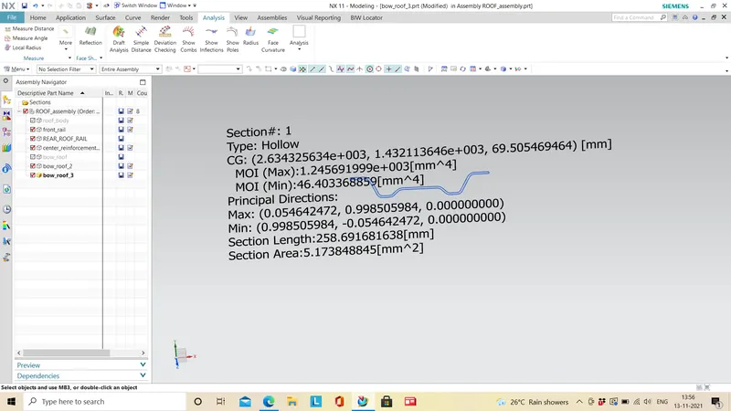
HEAT DISTORTION CRITERIA:
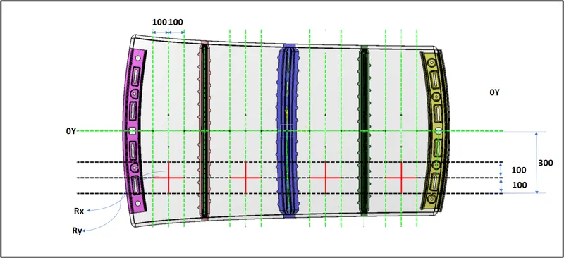
The locations where the length and the curvature are studied and calculated is shown below:
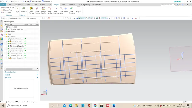
To measure the arc length in the section we create points minimum of three on the section at the intersection of the lines as shown below:
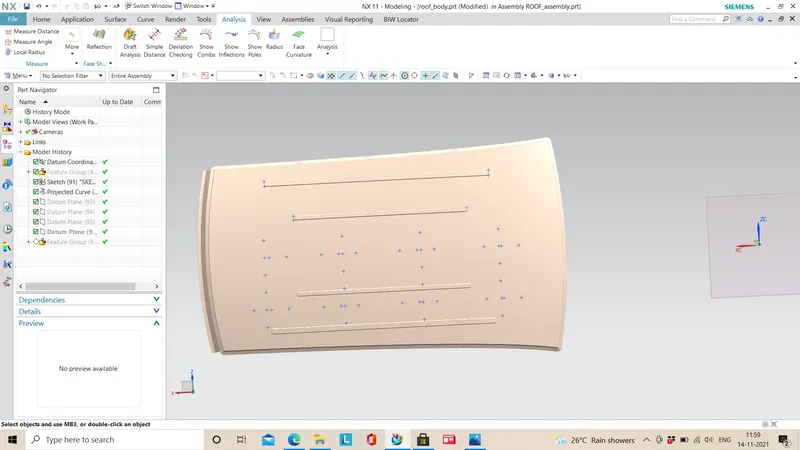
The values are measured as per the following image:
W = [1.73 x 10^(-3) x L] + [1.85 x 10^(-8) x (R^2)/t] + [ 1.10x10^(-3) x l] - 2.68
OK< 2.7> 3.1 , less than 2.7 is also accepted.
Where
L = Roof Length in X-Direction[mm](Roof dimension in 0-Y)
R = Roof curvature
R = 2(Rx*Ry)/(Rx+Ry)
Rx = X curvature
Ry = Y curvature
t = Roof plate thickness [mm]
l = Bow Roof Span [mm]
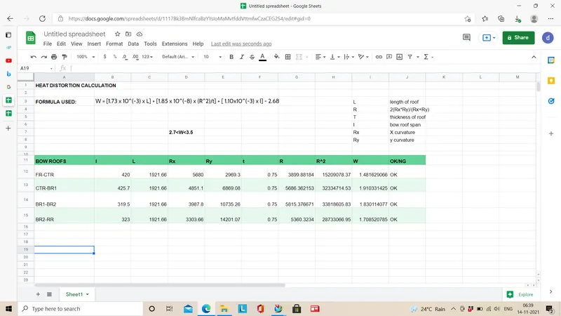
The heat distortion criteria for all the cases are under 2.7 and it is essential to avoid the exceeding of 3.5
SNOW LOAD CONDITION:
Qr = [Iy x t2] / [α x s x [(Rx + Ry)/2]2 x 10-8]
Where
α = My x Lx2 x 10-12 , My = Y(Ly-Y)
Judgement condition = Qr ≥ 3.1
250 ≤ s ≤ 380
t = Roof plate thickness [mm]
Ly = Distance between the front and rear roof Rails on the Vehicle along with 0Y[mm]
Length of Roof panel with the center point between Roof rail Front /Rear as the front and rear reference point.
Lx = Distance between the Left and Right end of the roof on the Roof BOW [mm]
Width of the roof panel exposed on the surface.
Y = Distance front Front Roof Rail to Roof BOW[mm]
s = Distance for which Roof BOW bears divided load [mm]
s = L1/2 + L2/2
Iy = Geometrical moment of inertia of Roof BOW (Y cross-section )[mm4]
Rx = Lateral direction curvature radius of roof panel Y cross-section on Roof BOW [mm]
Roof panel curvature Radius of the Length Lx in Front view
Ry = Longitudinal Direction curvature radius of the Roof panel X cross-section on Roof BOW [mm]
Roof panel X curvature radius of length s in Side view
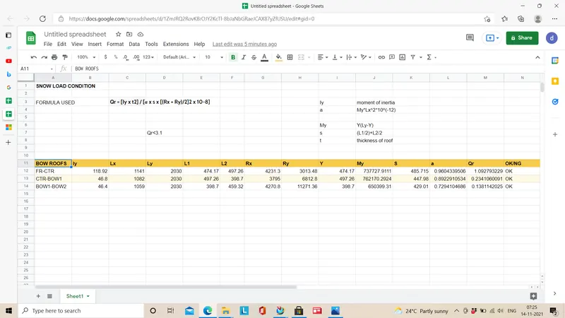
The snow load values are less than 3.1.,but the s values are greater than 380mm.
FINAL ASSEMBLY:
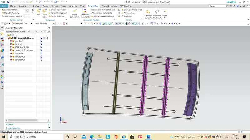
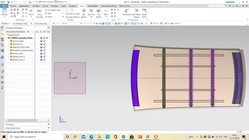
This is the final assembly of the roof.
ACHIEVEMENT:
- The roof is designed according to the master section given successfully.
- Front roof rail,rear roof rail,center reinforcement,bow roofs are designed and placed at respective positions
- The curvature study of the roof is done for bow roof positioning.
- Analysis of heat distortion and snow load condition is studied and calculated.
- The roof and other parts are assembled in a assembly file.
REFERENCES: