Roof challenge
Challenge:
- In the given challenge module of roof styling is to develop the essential flanges with reinforcements and embossed surface to strengthen the rails
- Do a curvature study on the roof..
- Calculations to determine the position of the bow-roof.
Roof is the structure above the head room which helps to protect the vehicle occupants from sun, wind, rain, and other external elements.
A hardtop is a rigid form of automobile roof, which for modern cars is typically constructed from metal. A hardtop roof can be either fixed (i.e. not removable), detachable for separate storing or re-attachable within the vehicle itself.
A sunroof is a panel on the roof of a car that either slides back or can be taken out to allow light, air or both to come into a vehicle.A sunroof was traditionally an opaque panel that matched the color of the car's body. Drivers could tilt it open or remove it completely.
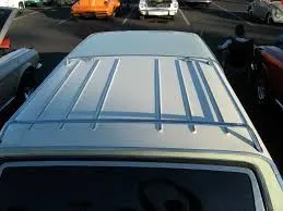
A moonroof is considered a type of sunroof,but a moonroof usually has a tinted glass panel, much like an extra window, on top of the car. It is designed to let the moonlight in. Unlike a traditional sunroof, moonroofs are not designed to be removed from the vehicle, although they usually slide or tilt open.Many moonroofs come with an interior sliding panel that matches your car's interior.When it is closed, no light comes into the car. Once this panel is open, the moonroof is revealed.
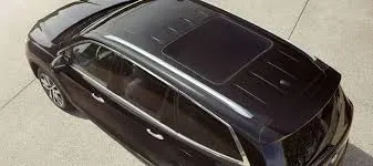
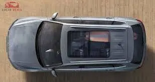
Panoramic roof features large glass panels on the entire length of the vehicle roof. These let light into both the front and back seats. This type of roof comes in two styles: fixed in place or with glass panes that slide open and closed.
Design Intend :
- Must satisfy the minimum clearance for head room area
- Heat distortion test
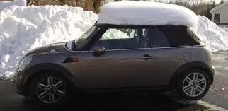
- Snow load test
- Draft analysis
Head room is measured as the vertical distance from the seat bottom to the roof. The maximum and minimum values arise if the car has height adjustable seats. so to design a roof head roof is very important for the passenger comfort level there must be.
Manufacturing Process:
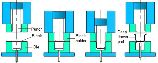
Deep Drawing :
The total drawing load consists of the ideal forming load and an additional component to compensate for friction in the contacting areas of the flange region and bending forces as well as unbending forces at the die radius. The forming load is transferred from the punch radius through the drawn part wall into the deformation region (sheet metal flange). In the drawn part wall, which is in contact with the punch, the hoop strain is zero whereby the plane strain condition is reached. In reality, mostly the strain condition is only approximately flat. Due to tensile forces acting in the part wall, wall thinning is prominent and results in an uneven part wall thickness, such that the part wall thickness is lowest at the point where the part wall loses contact with the punch, i.e., at the punch radius.
Bending :
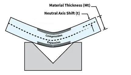
Bending is a process by which metal can be deformed by plastically deforming the material and changing its shape. The material is stressed beyond the yield strength but below the ultimate tensile strength. The surface area of the material does not change much. Bending usually refers to deformation about one axis.
Components of a roof:
Roof Outer Panel and Ditch Area:
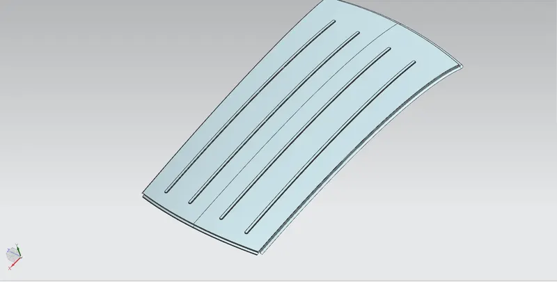
Roof outer panel is made of sheet of at least 0.75 mm which protects the cabin from external conditions and objects. The ditch area is the extended portion of the main roof concealed by the other BIW panels.The rail supports of the roof are attached to the ditch area using spot welds. Some of the factors considered while designing ditch areas are Headroom clearance, visibility criteria,clearance windshield and back door.
Front Roof Rail
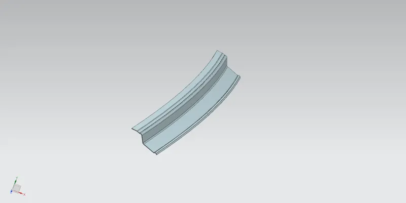
It lies at the front part of the roof. It provides strength to the roof panel front. It is the support which is joined with the wind shield glass, body side outer and the inner panels. The draft angle of 3-5 degrees is provided keeping in mind the deep drawing operation. The bottom most flange is designed by considering the head room clearance and visibility criteria.Spot welds are applied at wind shield end of the rail and the other end is joined with the roof using mastic sealants which also contributes to increased strength.
Rear Roof rail
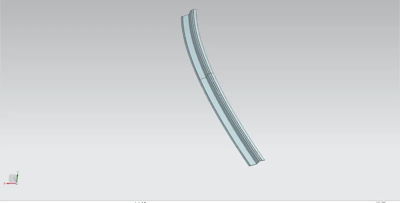
It ties at the rear part of the roof. It provides strength to the roof panel rear. It is the support which is joined with the back door, body side outer and inner panels. The design consideration is same as of the front roof rail but here inputs from the back door design is also taken into consideration to accommodate the required clearance. Spot welds are applied at the back door end of the rail and the other end is joined with the roof using mastic sealants.
Reinforcement Roof Center:
This is the roof rail that lies between the B-pillar of the car and provides support to the center of the roof. They are usually 1-2 mm thick which provides a support area for the center cabin light mount. While designing the head room clearance and visibility criteria is taken into consideration.The roof is fixed to the roof rails with the use of mastics and the ends are spot welded.
Bow Roof Rails:
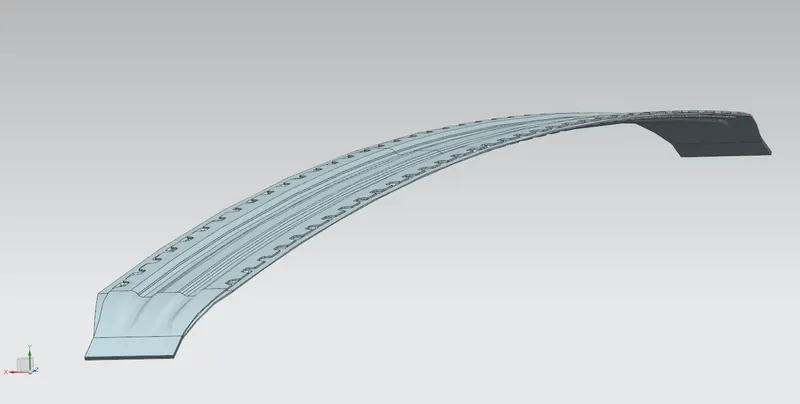
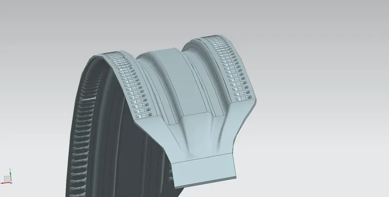
The bow roof rails provide additional support to the roof. They are positioned in such a way that they provide maximum support to the roof.They are designed in such a way that they don't intrude into the head room requirement of the car. Bow roof rails are the additional features provided as per the requirement. Small cars may have no bow roof while the large cars may have 2 or more. If there is the sunroof then the bow roof is integrated into the center roof rail. The roof is fixed to the bow roofs with the use of mastics while the ends are spot welded.
Bow–roof prediction Formula
W = [1.73 x 10^(-3) x L] + [1.85 x 10^(-8) x (R^2)/t] + [ 1.10x10^(-3) x l] - 2.68
Judgement Condition : OK< 2.7> 3.1
Where
L = Roof Length in X-Direction[mm](Roof dimension in 0-Y)
R = Roof curvature
R = 2(Rx*Ry)/(Rx+Ry)
Rx = X curvature
Ry = Y curvature
t = Roof plate thickness [mm]
l = Bow Roof Span [mm]
Procedure to measure Rx & Ry:
- Consider a plane above the roof at some distance & enter the sketch workbench.
- Draw a line at -3Y at -300mm from the O-Y axis and offset it to the 100mm on both sides of -3Y lines.
- Draw vertical lines between every two adjacent roof rails. Make these lines as reference lines.
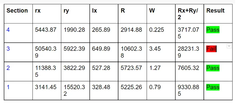
Snow load Prediction formula
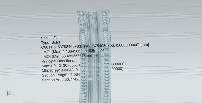
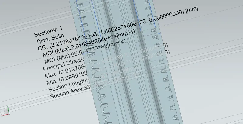
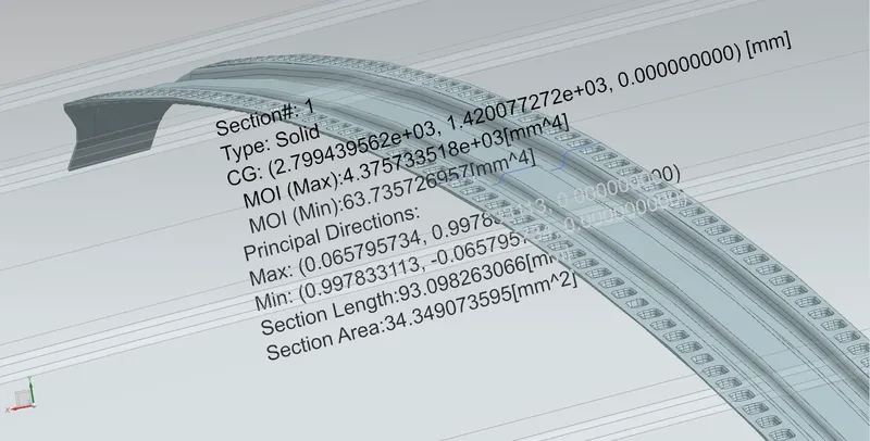
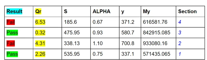
Qr = [Iy x t2] / [α x s x [(Rx + Ry)/2]2 x 10-8]
Note: The Qr value given over here is correct. There was a typo error in the formula given in the video.
Where
α = My x Lx2 x 10-12 , My = Y(Ly-Y)
Judgement condition = Qr ≥ 3.1
250 ≤ s ≤ 380
t = Roof plate thickness [mm]
Ly = Distance between the front and rear roof Rails on the Vehicle along with 0Y[mm]
Length of Roof panel with the center point between Roof rail Front /Rear as the front and rear reference point.
Lx = Distance between the Left and Right end of the roof on the Roof BOW [mm]
Width of the roof panel exposed on the surface.
Y = Distance front Front Roof Rail to Roof BOW[mm]
s = Distance for which Roof BOW bears divided load [mm]
s = L1/2 + L2/2
Iy = Geometrical moment of inertia of Roof BOW (Y cross-section )[mm4]
Rx = Lateral direction curvature radius of roof panel Y cross-section on Roof BOW [mm]
Roof panel curvature Radius of the Length Lx in Front view
Ry = Longitudinal Direction curvature radius of the Roof panel X cross-section on Roof BOW [mm]
Roof panel X curvature radius of length s in Side view
Draft analysis:
No component can be ejected at 90 degree angle; there should be some draft given for easy removal after performing the respective operations to form a sheet metal component. The minimum draft angle of 7 degree should be provided for the Sheet Metal components so that there shall be no deformation in the component after it is removed from the punching or any other operation.
Draft analysis is performed on each and every Sheet Metal component with minimum 7 degree draft angle and the results are satisfied.
Conclusion:
- As per design guidelines Outer roof, Front roof rail, Bow roof-1, Center rail roof, Bow roof-2 and Rear roof rail are designed.
- The designs fulfill the Heat adsorption criteria and Snow load criteria.
- Draft analysis performed to check tooling feasibility. Results are satisfactory.
Drive link : https://drive.google.com/file/d/11OXC4KOGmuwQLv4zduUTNAlO7naEH8ry/view?usp=sharing