Radar Mast & Final Assembly of Yacht
Aim : To model a Yacht in order to assemble and render in solidworks visualize.
Objective:
- To develop principles and skills to design any product
- To get a good understanding of various features such as project curves,blocks, sketch patterns etc.
- To understand use of decals and and make use of it in model
Software used :
Solidworks : Currently to complete this project I have used the Solidworks 2021 version. Solidworks is published by Dassault Systems it was first released in the year of 1995
Solidworks Visualize : It is a stand alone product of solidworks itself specifically used for high quality rendering. It comes along as an additional add-in to solidworks license holders after the 2016 version.
Feature Used : To design this model I have used a hybrid design which is a mixture of solid and surface features. All the features that I have used are mentioned and explained.
Solid Feature :
- Extrude : This is the most fundamental feature which is used to convert 2-dimensional into 3-dimensional. This feature adds material perpendicular to its direction.
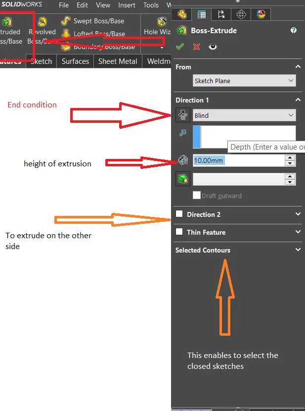
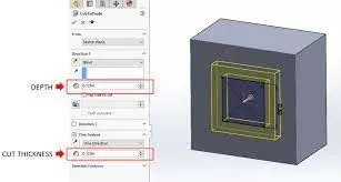
2. Extrude Cut : Similar to extrude, the only difference is that it removes material from the sketch.
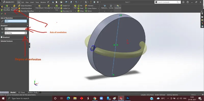
3.Revolve : The Revolve tool revolves the sketch around the axis of revolution to generate a solid.
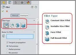
4.Fillet : It is applied on sharp edges to round off edges and/or corners by adding or removing material, depending on whether the edge is internal or external.
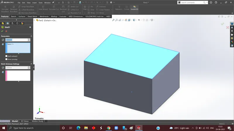
4. Shell: In these the material is removed from the inner body of the model by keeping small thickness and results in a hollow model.
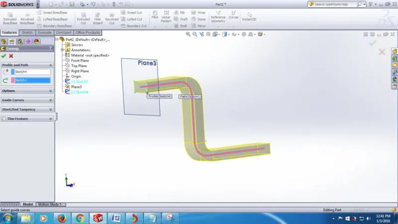
5. Sweep Boss/Base :Sweep creates and adds material by moving a profile (section) along a path.
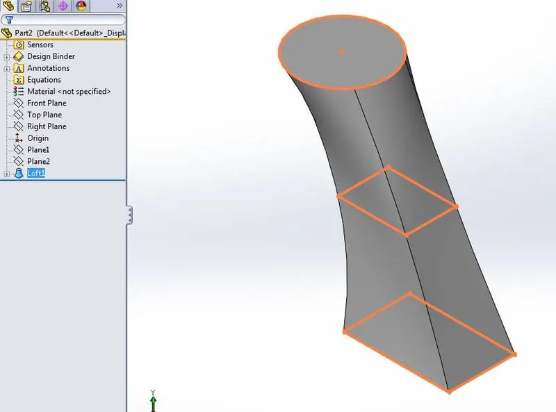
6. Loft Boss/ Base: The loft features one of the most important tools for (surface) modelling in SolidWorks. The loft feature creates a shape by making transitions between multiple profiles and guide curves.
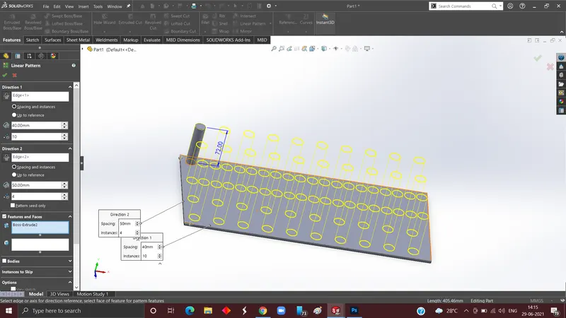
7.Linear Pattern: linear patterns mainly used to create multiple instances of one or more features that you can space uniformly along one or two linear paths.
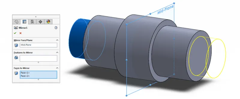
8. Mirror: Creates a copy of a feature, (or multiple features), mirrored about a face or a plane. You can select the feature, or you can select the faces that comprise the feature.
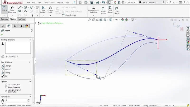
9.Projected Curve: By sketching two sketches on two perpendicular planes and then merging them to create a new 3D curve by using these two sketches as reference.
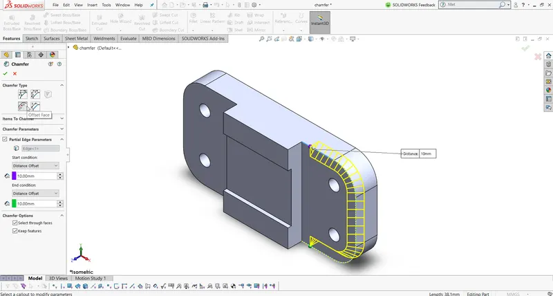
10.Chamfer : This feature is used to create symmetrical and asymmetrical sloping edges.
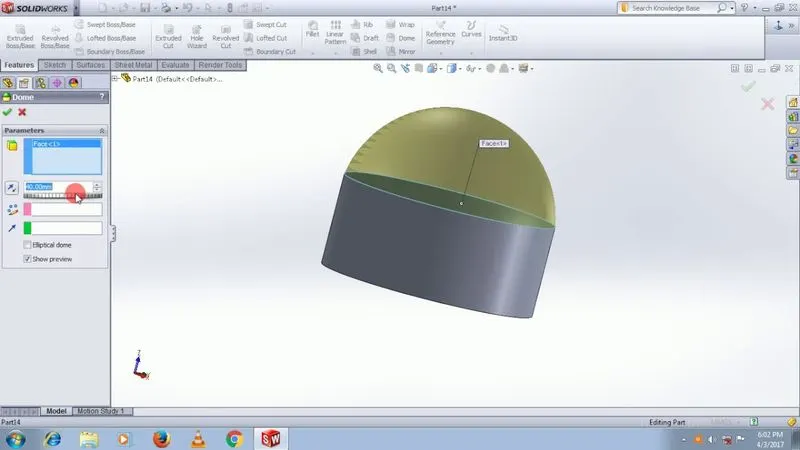
11.Dome : It is used to create a spherical faces on the top of the surface
Surface Feature :
- Extrude/Cut Extrude : similar to solid extrude it also add surface instead of material perpendicular to its sketched plane, and another difference is it adds surface to sketch geometry with negligible thickness.Similarly removes the surface.
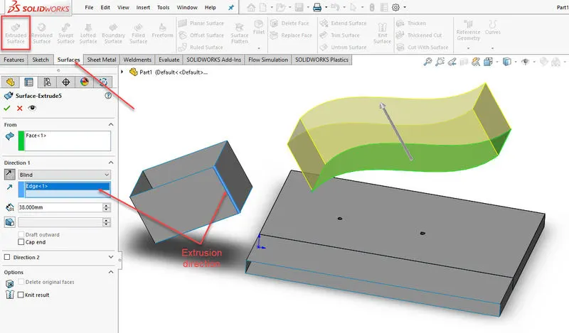
2.Lofted Surface : This feature adds surface between different geometries on different planes with the help of guide curves and centrelines
3.Swept Surface/ Cut Swept surface : In this we first specify direction to add surface and then create profile.
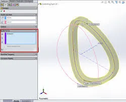
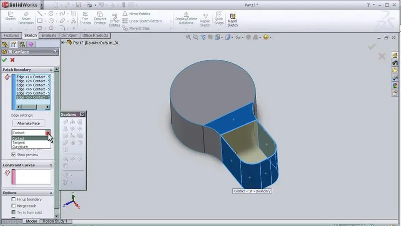
4. FIlled Surface To use this we first need to create a close surface then by selecting a boundary to add a surface along it.
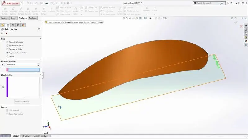
5.Ruled Surface : A ruled surface can be described as the set of points swept by a moving straight line.
6.Extent Surface : first we need to select an edge or face which we want to extend.
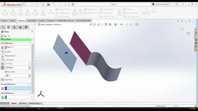
7.Trim Surface : This feature is widely used for trimming extra surfaces by reference plane sketch or edge.
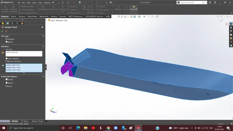
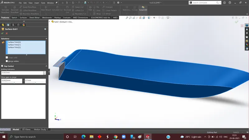
8.Knit Surface : This feature helps to add multiple into one, another use of this feature it also adds surface if there is a minor gap which is less than 0.1mm and creates a solid geometry.
Methodology:
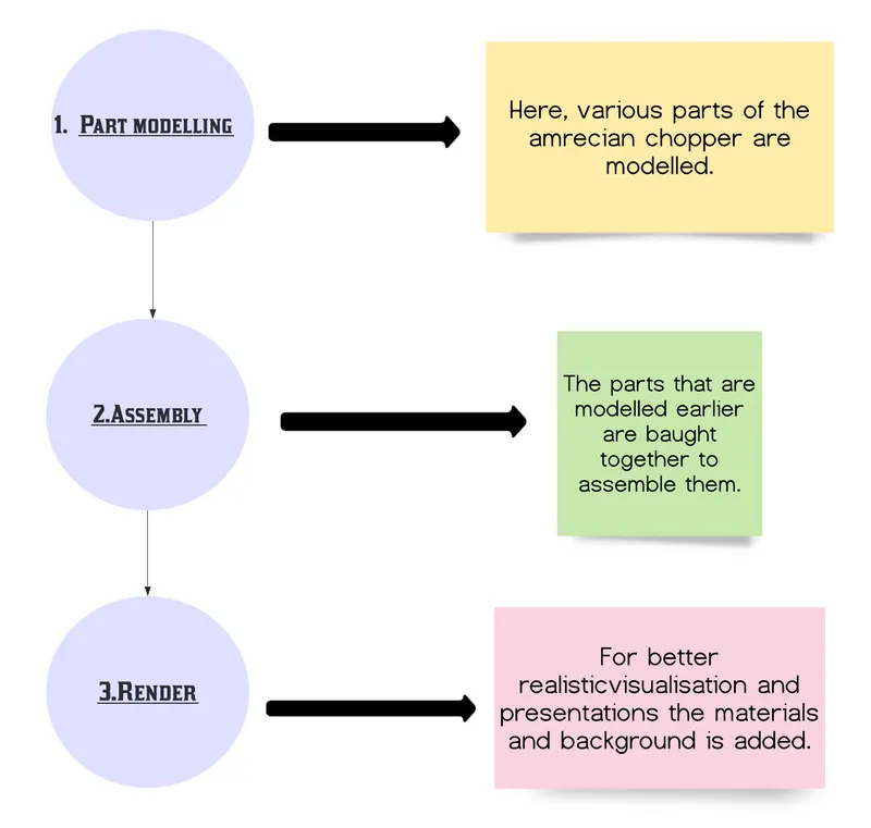
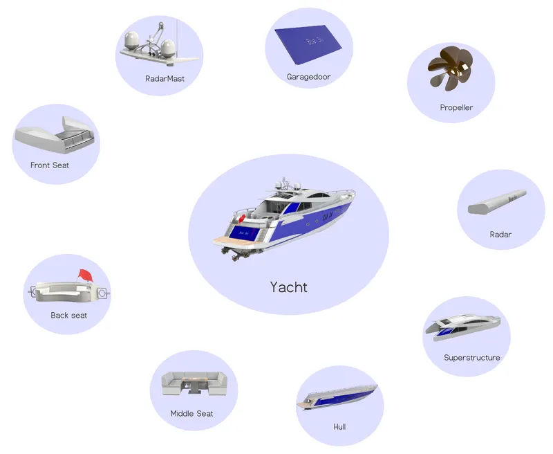
1.Part Modelling : This is the process of converting 2D sketch into 3D model with the help of basic part features(extrude,revolve,sweep etc..), the outcome of this procedure can be termed as “Virtual prototyping”. Different parts of assembly (Yacht) such as hull,superstructure,Front seat,middle seat,radar etc… are modelled here.
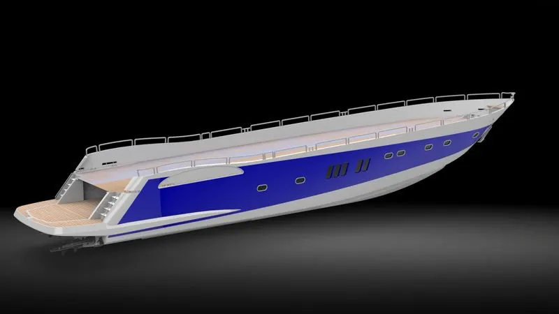
1.1 Hull : A hull is the watertight body of a ship, boat, or flying boat. The hull may open at the top (such as a dinghy), or it may be fully or partially covered with a deck. To model this I first need to import the blueprint into solidworks on appropriate planes. Then I have to first model the base on either the left or right part of the deck so that I can mirror it in the end. Once this is done then I have to make a garage part in order to make a garage door I subtract the inside part as a separate body and save it to use it later. Once the whole base is ready I mirrored the entire base with the reference of a midplane. Then to make it more real I have added decals to its surface.
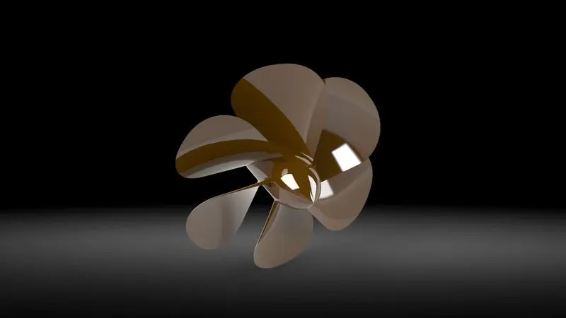
1.2 Propeller : It is a rotating fan-like structure which is used to propel the ship by using the power generated and transmitted by the main engine of the ship. To model this I first created a middle shaft by a revolving sketch. For its blade I sketch then use the loft command.
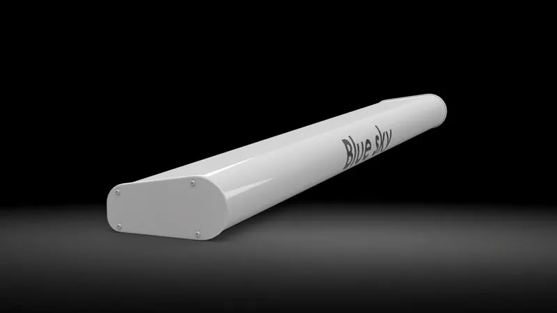
1.3 Radar: It is used to detect other ships and land obstacles, to provide bearing and distance for collision avoidance and navigation at sea. To model this I first extrude the part and then I add a text.
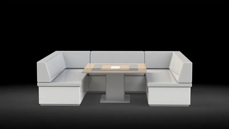
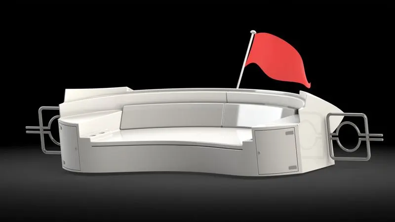
1.4 Front,middle and rear seat : To start modelling of this I first inserted the surface from hull part so that I can use this as a reference and I can create a model above it.Here I used part commands such as extrude, revolve and for flag I first modeled all the boundary and then use fill feature to add surface between this.
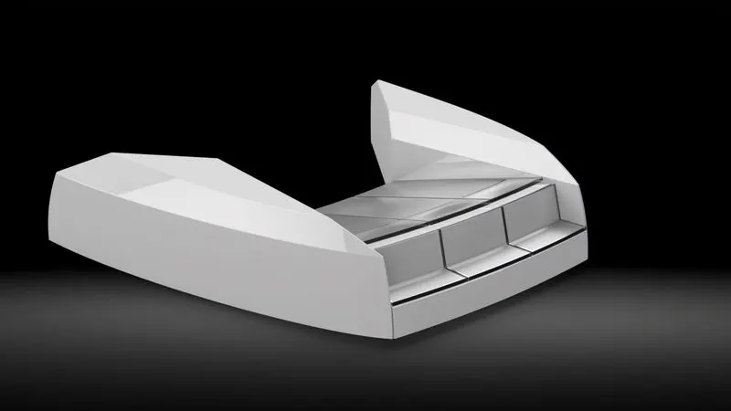
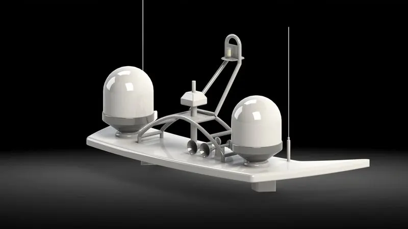
1.5 Radar mast : It is a detection system that uses radio waves to determine the distance (range), angle, or velocity of objects. It can be used to detect aircraft, ships, spacecraft, guided missiles, motor vehicles, weather formations, and terrain. In order to create this I first modeled half part of it and then used a mirror feature to mirror it.
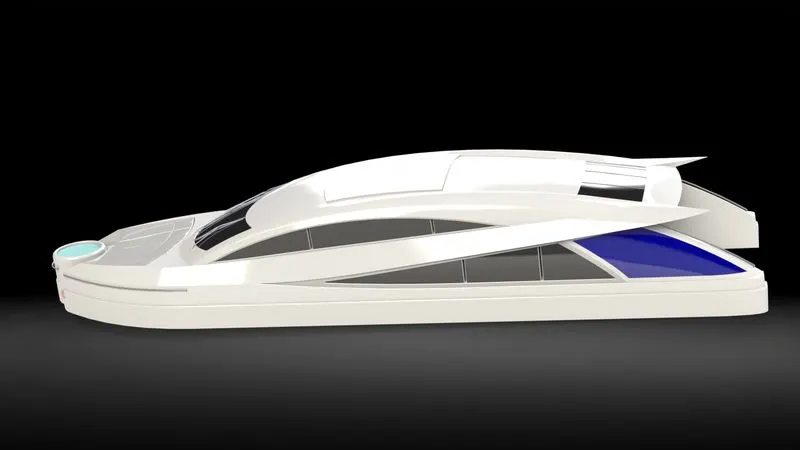
1.6 Superstructure is an upward extension of an existing structure above a baseline.To create this I first inserted a surface of hull so that on the top of it I can model this part. Then I modeled half part of it by using some 3D sketch,project curve, loft etc
II.Assembly
After creating each and every part of “Yacht” individual parts are being imported in the assembly workbench, lastly mates are applied to restrict their movement(Degree of freedom). Most widely used mates are coincidence,concentric,tangent,parallel which in solidworks comes with an individual category termed as “standard mates”.
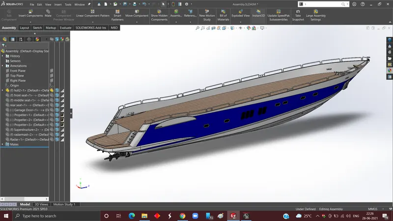
1.) I have started my assembly by inserting the hull part into the assembly workbench for that I need to click on the “Insert component” feature on the ribbon menu then specify the path and then I need to click on the “Ok” button so that it gets automatically aligned with assembly planes.
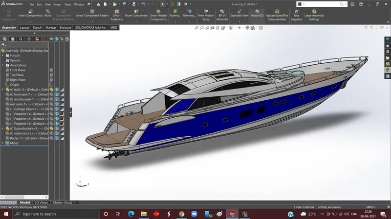
2.) Next step is to import the superstructure when it's being imported. I clicked on ok again and this gets automatically aligned. This is because while modelling it I already inserted the top reference surface of the hull into our parts so that its position gets automatically fixed. our parts so that itits position gets automatically fixed.
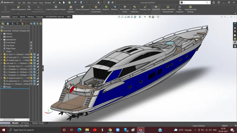
3.) Follow up to the previous step in this. First I need the front and middle seat and then again click on “ok” to position it. Now for rear seat I have to import rear seat and then give a coincident mate to middle planes of hull and rear seat, again coincident mate is given to top surface of hull and bottom surface of rear seat . Lastly , distance mate is applied to the middle point of the back top and back surface of the rear seat. At this stage all the seats are imported and constrained properly.
4.) Next step is to again click on import specify path for garage door again and apply concentric relation to back door to the cylindrical part of back garage and the hole.
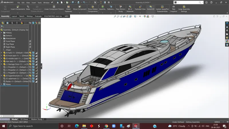
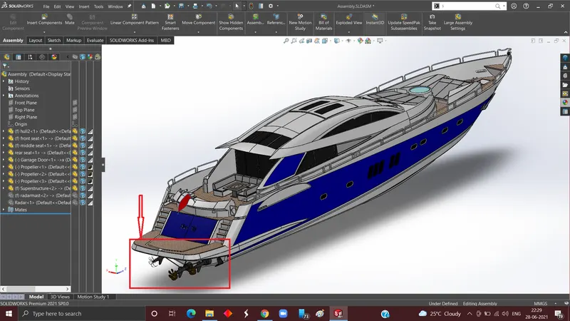
5.) Now it's time to insert the propeller into our model and immediately after that concentric relation is given to the shaft and propeller. This procedure is required to repeat two more times because there are total shaft in our model.
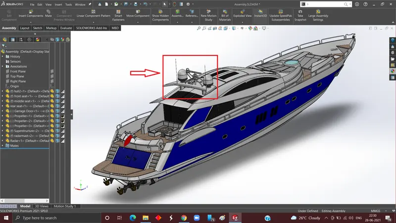
6.) Our last part is radar and radar mast, for radar there is no need to give any mates already they are placed while modelling so I just need to click on “ok” to position it properly. Concentric relation is given to radar and antenna of radar mast and bottom surface of radar hole and top surface of antenna.
III.Rendering:
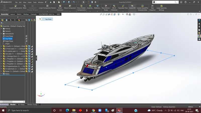
- Preprocessing: Before proceeding I need to check whether bottom plane is touching to the bottom surface so that the final render looks more realistic.
2.Rendering: This is the main phase in which we add many features and make the yacht more alive by adding things like background image so that we can visualize easily our final product in its actual environment. Now we need to adjust lights and camera so that model is visible and proper viewing also plays a important role.
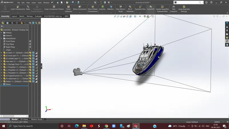
3.Post Processing: This is the final step in which some adjustments if needed are done such as contrast, size and aspect ratio of the image.
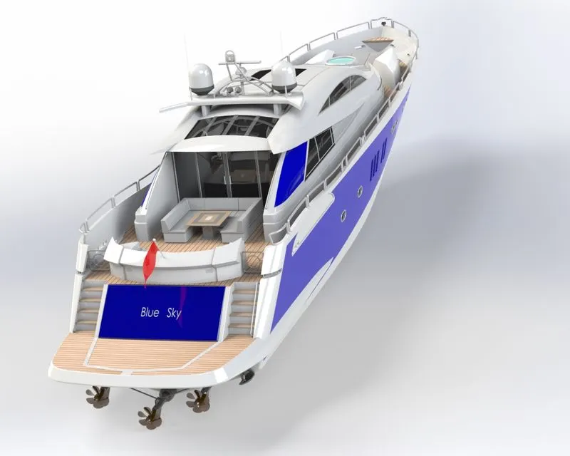
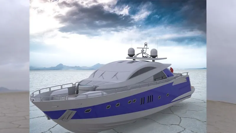
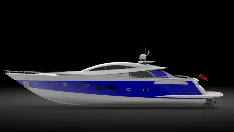
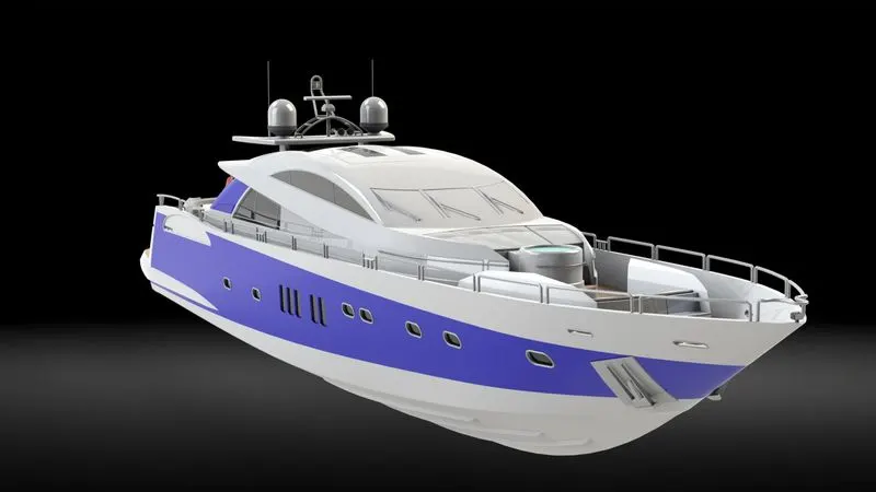
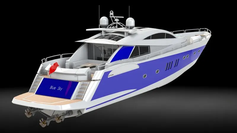
Conclusion : Three dimension model is created by applying fundamental features on solidworks in part as well as suface workbench and then rendered in solidworks to visualize for better photo realistic images.
Drive link : https://drive.google.com/file/d/1QLfDTmeqxsgV8BXf9yz8elHaJAsbJATj/view?usp=sharing