Advanced Sheet Metal Design Using NX Cad Challenge_1_Casing Design
Tittle : To design a casing using NX-CAD sheet metal
Objective :
1.) To understand the concept behind design
2.) To get familiar with NX-CAD sheet metal workbench
Introduction :
Sheet Metal : It is a comprehensive cold working process for sheet metal (Usually below 6mm).Thicknesses of this sheet can vary significantly extremely thin to the thicker sheets, thinner sheets are generally considered as foil or leaf and pieces thicker than 6 mm (0.25 in) are considered plate steel. There are many different metals that can be made into sheet metal, such as aluminium, brass, copper, steel, tin, nickel and titanium. Sheet metal is used in automobile and truck (lorry) bodies, airplane fuselages and wings, medical tables, roofs for buildings (architecture), and many other applications. Generally there are two types of region in any sheet metal are web and bend region. COMMON BENDING OPERATIONS GENERALLY used are Press brake forming, Air bending ,Roller bending , Beading,Flanging , Hemming , Roll forming , Stretch forming,Deep drawing.
NX-CAD Sheet metal Workbench : With Sheet metal CAD tools, you can apply standard values, such as material thicknesses and bend radii, based on industry or company best practices. With folding and unfolding capabilities, you can work with models at any stage of the fabrication process. Sheet metal parametres creates accurate flat patterns for documentation and manufacturing.
Methodology :
To achieve a final product the methodology is followed is
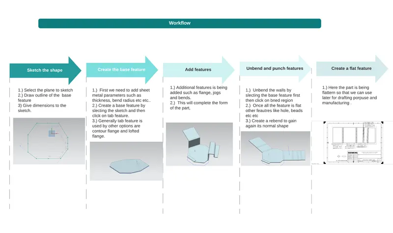
fig.1
Features Used :
1.TAB: Usually this feature is the first feature used to create a base feature by extruding a sketch along a vector by a thickness value or adding a material to a plane face. The sketch can be of any shape only if it has to be closed.
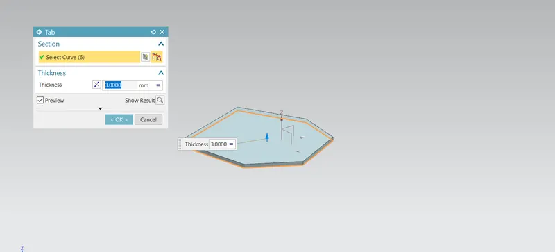
fig.2
2.FLANGE: This feature adds a flange/wall on edge; it can be at an angle to a planar face and adds a bend between the two adjacent edges. First we need to select the edge then specify height and angle.
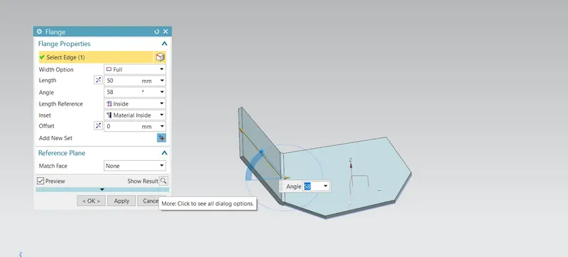
fig.3
3.DIMPLE: By sketch on a it lifts an area of the model inside a closed sketch that simulates stamping a tool.
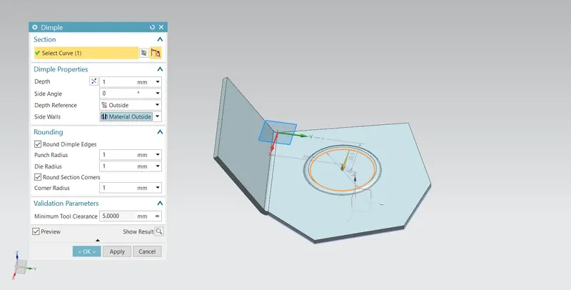
fig.4
4.UNBEND: It flattens a bend by first selecting the flat surface and then clicking on the bend region.
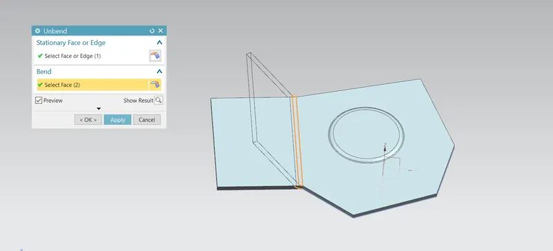
fig.5
- BREAK CORNER: It Rounds a sharp corner by selecting an edge and then specifying the radius of it.
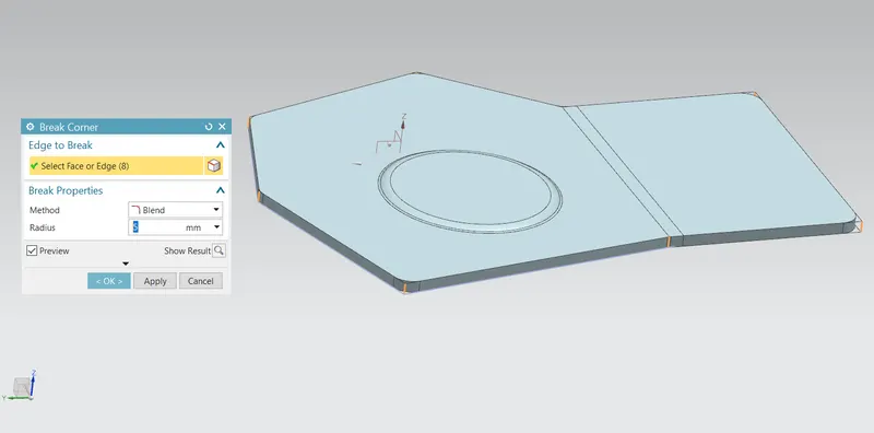
fig.6
- NORMAL CUTOUT: It cuts the sheet metal part by sketching the profile for cutout and then it cuts the sheet perpendicular direction to the sketch plane.
fig.7
- Hole : First step is to locate the point by sketching on the plane the points are the centre of the hole. Then click on hole feature on the ribbon tab and select the point that you sketch earlier and give the diameter.
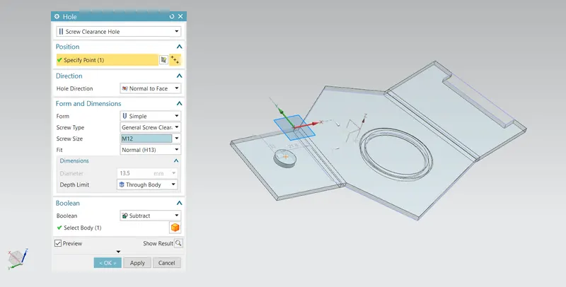
fig.8
- REBEND: It restores the bend by just selecting the bend region.
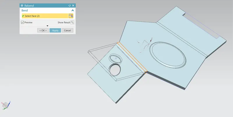
fig.9
- BEAD: It is a stamping tool that lifts a material along a counter of a sketch that simulates stamping a tool.
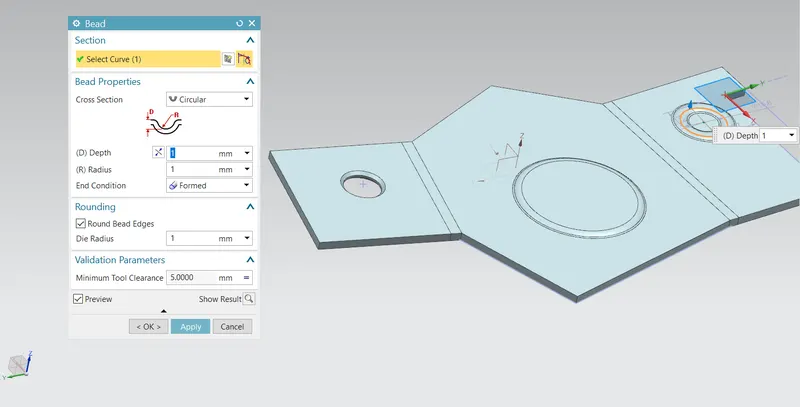
fig.10
- FLAT PATTERN: Creates flat pattern feature from the formed sheet metal part.
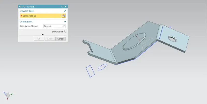
fig.11
Steps to be followed :
Step 1:
Sketch the base closed profile and then apply the dimension. Specify the sheet metal parameters such as thickness, bend radius and relief width and depth. By clicking on the tab feature select the sketch first base is created.
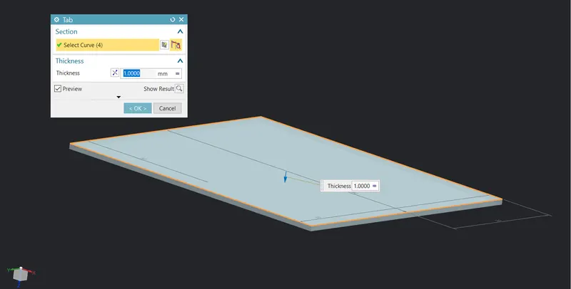
fig.12
Step 2:
To create a cutout first create a close surface and then click on the cutout.
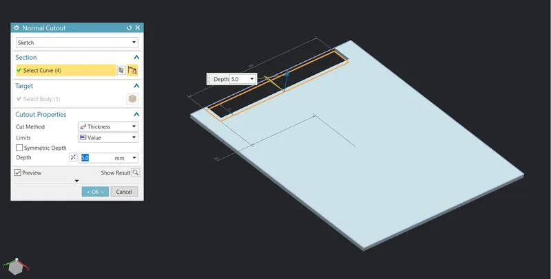
fig.13
Step 3:
In this the bend line is being sketch on plane then add a bend or wall on edge.
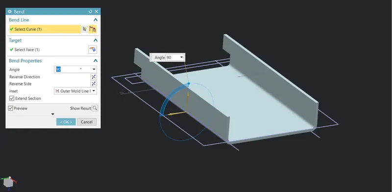
fig.14
Step 4 :
The flange is now created by just selecting the edge and then specifying the edge length and making sure that material is added inside.
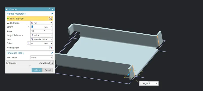
fig.15
Step 5 :
Now the sharp edge is changed into curved edges. The reason behind doing this is that it doesn't have any problems while manufacturing the part.
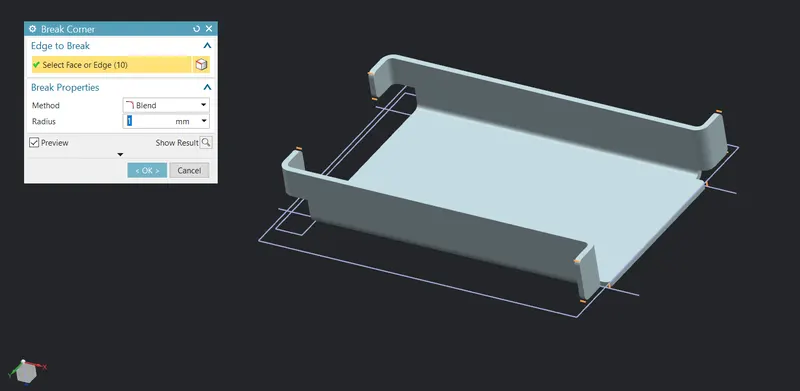
fig.16
Step 6 :
Here, all the edges are unbend to perform features like hole, stamping etc etc to be done on the part.
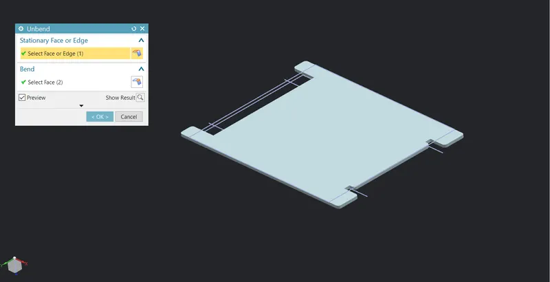
fig.17
Step 7 :
Once the part is unbend hole is being done on the surface by sketching a point as the centre of the hole and then specifying the diameter and depth of the feature.
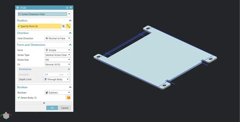
fig.18
Step 8 :
To create the centre punch on the feature first sketch is drawn on an appropriate plane then select the dimple feature and give the lateral radius and punching depth.
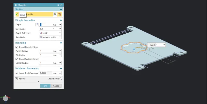
fig.19
Step 9 :
By selecting the bead feature this will lift the sheet from where it was sketched. Then mirror it using standard planes
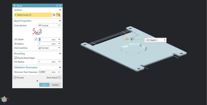
fig.20
Step 10 :
Here, all the bend regions are unbend to regain its original shape once all the additional features are applied to the part.
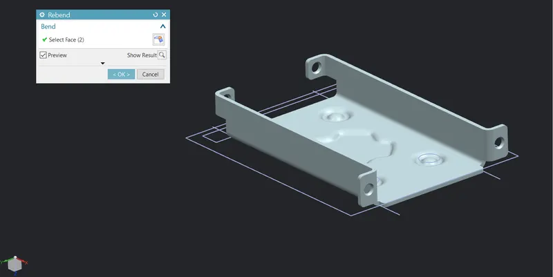
fig.21
Step 11:
In this last step the final part is flattened so that it can be drafted and sent to the manufacturer for manufacturing with detailed drawing and dimensions.
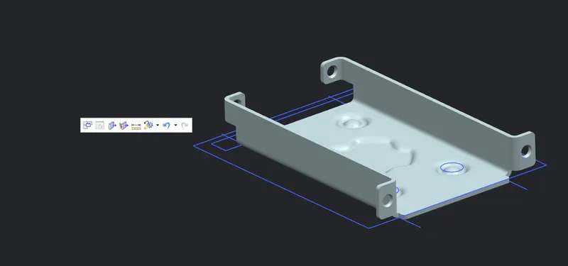
fig.22
Some Views standard images
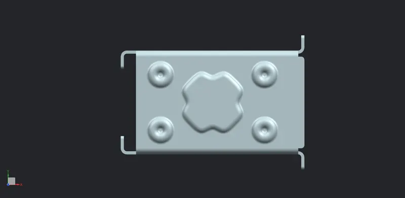
fig.23
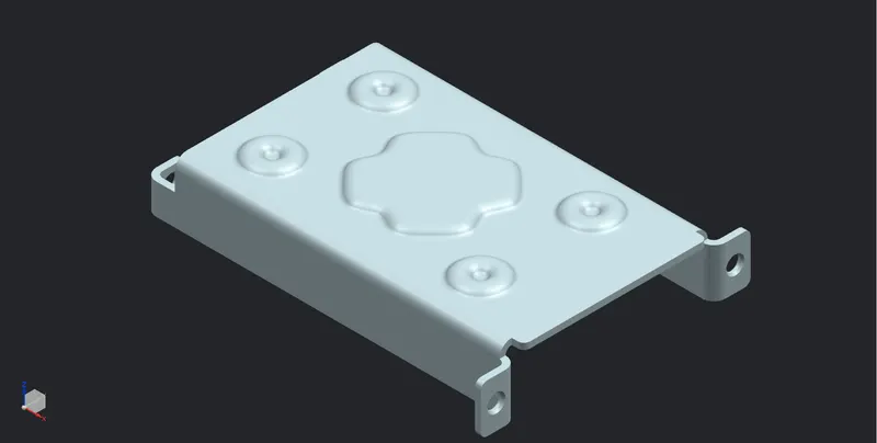
fig.24
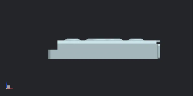
fig.25
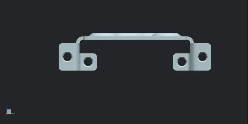
fig.26
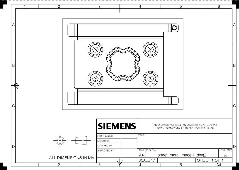
fig.27
Conclusion :
Hence the casing is being modelled in NX-CAD by using some basic and advanced features.