American Chopper(Bike)
Aim : To design a CAD model of american chopper in order to assemble and render in solidworks.
Objective:
- To develop principles and skills to design any product
- To get a good understanding of various features such as project curves,blocks, sketch pattern etc.
Software used :
Solidworks : Currently to complete this project I have used the Solidworks 2021 version. Solidworks is published by Dassault Systems it was first released in the year of 1995
Solidworks Visualize : It is a stand alone product of solidworks itself specifically used for high quality rendering. It comes along as an additional add-in to solidworks license holders after the 2016 version.
Feature Used :
- Extrude : This is the most fundamental feature which is used to convert 2-dimensional into 3-dimensional. This feature adds material perpendicular to its direction.
- Extrude Cut : Similar to extrude, the only difference is that it removes material from the sketch.
- Revolve : The Revolve tool revolves the sketch around the axis of revolution to generate a solid.
- Fillet : It is applied on sharp edges to round off edges and/or corners by adding or removing material, depending on whether the edge is internal or external.
- Shell:In these the material is removed from the inner body of the model by keeping small thickness and results in a hollow model.
- Sweep Boss/BaseSweep creates and adds matreial by moving a profile (section) along a path.
- Loft Boss/ Base: The loft features one of the most important tools for (surface) modelling in SolidWorks. The loft feature creates a shape by making transitions between multiple profiles and guide curves.
- Linear Pattern: linear patterns mainly used to create multiple instances of one or more features that you can space uniformly along one or two linear paths.
- Mirror: Creates a copy of a feature, (or multiple features), mirrored about a face or a plane. You can select the feature, or you can select the faces that comprise the feature.
- Projected Curve: You can project a sketched curve onto a model face to create a 3D curve.
Methodology:
:
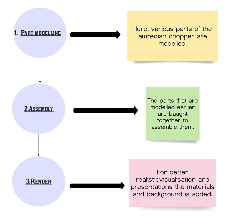 Fig. 1
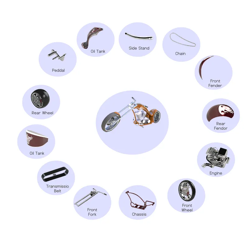
1.Part Modelling : This is the process of converting 2D sketch into 3D model with the help of basic part features(extrude,revolve,sweep etc..), the outcome of this procedure can be termed as “Virtual prototyping”. Different parts of assembly (American Chopper) such as Oil Tank,Chain,Front fork,Engine,rear and front wheels etc… are modelled here.
Kickstand - Major function of this part is to support the chassis by leaning on ground so that its weight gets transferred. To create this model I first sketched an ellipse on the front plane and another sketch followed by first which was later used as a spine curve in the loft feature. At the end of the spine curve I have put a reference plane on which I sketched another ellipse which is a bit comparatively smaller in size than the first one. With the help of the loft feature I have created a base body of kickstand, for nice and smooth edges elliptical dome is applied on both sides. In order to create a pin I removed material by extrude cut sketching on the right plane,next is to add a pin so that it gets hinged with the chassis and can be rotated back and forth. For better functionality I drew a straight line which later used to split the stand so that the body can lean properly on the ground. In the end for nice rounded edges I applied fillet features on sharp corners.
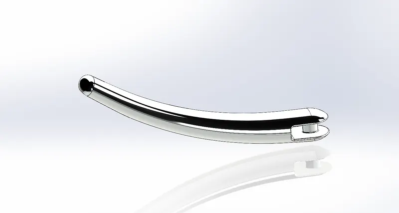 Fig. 2
Front/Rear Fender: Its primary use is to prevent sand,mud and stone which is thrown by rotating tyres on the rider. First step to create this is to sketch a profile and axis on the right plane then with the help of the revolve feature I revolve the sketch that I have drawn on both sides. In order to get sharp ends on both sides I sketched two independent sketches, one on a vertical plane and other on the centre plane to split and then cut the fender body. While creating the rear fender I used shell command so that I get a curve at the end. Both the parts are metal and painted sienna which gives a bright orange texture.
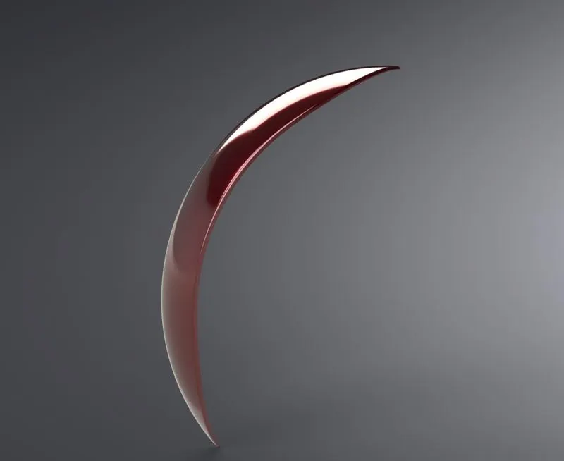
Fig. 3
Chain : This part is used to transmit power from engine to the wheel. The very first step to make this is to create a profile on the right plane which is the path of all chain links and pins are aligned. Then again choosing the right plane I created a sketch of inner and outer link and coveted it into a block so that I can call them repeatedly whenever there is need. Next task is to add materials to block with the help of extrude while using this feature instead of selecting sketches I selected contours and then pattern in order to do so I divided profile that earlier I drew into 4 different segment then I imported blocks and fill material and then did a curve driven pattern in each of these segments independently. A fine finished chrome plate metal is used as the appearance of the linked part.
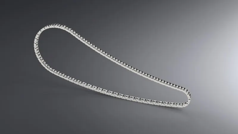
Fig. 4
Front/Rear Wheels : This helps to move the body linearly by rotating on its own axis. This rotation is produced due to friction between ground and wheels. To model this part I used a multibody approach that means after the model is completed there will be separate solid bodies such as rims,tyre,sprocket.Firstly, I sketched a profile and axis of revolution on the right plane so that I can revolve it. Next I draw a rim profile on the right plane and mirror extrude and un check on merge that results in creating a new body into a part design so that later I can sketch a spider web design and remove material from it. Likewise the brake disk is being created by the revolve command. In order to model the tyre I again sketch on the right plane and again revolve it and not merge the result. For grip on the tyre I first draw a profile on the front plane followed by an extrude cut and circular pattern on it. For the rear wheel the design approach is almost the same, only an additional part is sprocket.Now , at the end I applied some fillet and materials to make it look even more realistic. The entire wheel consists of five solid parts: Chrome finished Rims, Sienna metal painted Caliper, Chrome finished sprocket and matte rubber tires.
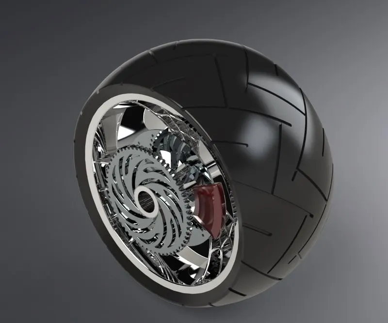
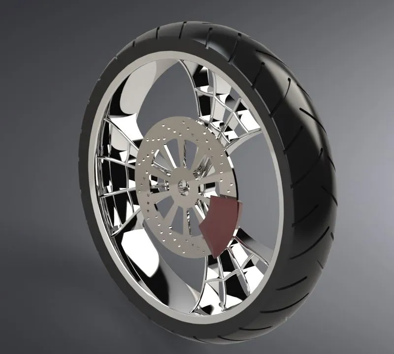
Fig. 5
Transmission Belt: It is widely used to connect and deliver power between two rotating objects. Transmission belt is modeled by using a single and most basic command i.e extrude boss base. The complete sketch is first drawn on the right plane then I extrude it from its plane. Material given to this is matte rubber.
Fig. 6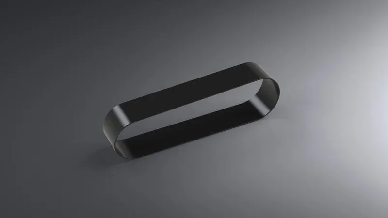
Oil Tank: It is used to store a lubricating liquid.The base of the oil tank is sketched on the Top Plane and extruded boss above now another sketch is made on the mid plane extruded and combined together and at last a shell function is used to make the part hollow and the edges are made round by applying fillet to attain a shape like oil tank. Again the metal body is painted with the same sienna color and the filleted edges are given a white paint.
Fig. 7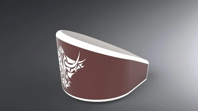
Pedal: Its functionality is to rest the foot while driving. The modeling of this part starts by sketching the base of pedal on the front plane and with the help of extruded base feature circular holes for the footrest and the pins which are extruded the second time, now a sketch is created on the top plane for the foot rest which is then revolved to make an more realistic model. Now on the top of the rest dome and the edges and joints are filleted to avoid sharp cuts, the front and the rear extruded cylindrical parts are then chamfered to attain a proper finish and a circular pattern is extruded on each of the front facing extrudes which are then arranged using linear pattern and fillet is applied to all the edges and the joints of the last pattern. 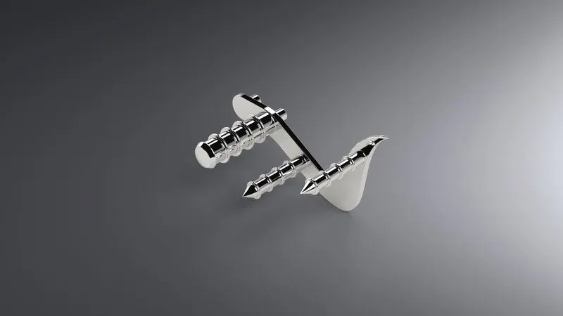
Fig. 8
Front Forks: - It prevents overloading of the front wheel and absorbs any vibrations.This part consists of front fork, handle bar, head lights, break and clutch levers, wires and handle grips. The approach towards this model is to create either side of the fork(half part of the fork) and then mirror it along the mid edge. The first step begins with revolving a cylindrical fork along right plane then on the top of it the face is sketched and extruded which is mirrored and linearly patterned then with two cylindrical extrudes to join the upper deck and the mirror side of the fork. Another extruded part is curved along the top of the handle facing down which is the headlight. The edges of the part is filleted to give it a headlight curved and realistic look.By using two curve used to form a projected curve and similarly on the front face of the swept area handle grips are made using the revolve feature and on the inner face of handle bar we draw the geometry required for the levers and extrude them the sharp edges are filleted and then comes another projected curve made to sweep the wires for the brake and clutch now we create a plane from which the other side of the fork is mirrored and all the parts are combined together to form the desired 3D shape.
Fig. 9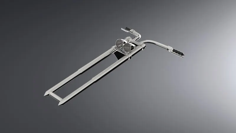
Chassis: It helps to support all the parts .The model this part I first draw two projected curve that then result lower curved path of the block which then use as a path for sweep feature.A sketch is then made and extruded from the open end of the base and excess material is removed from it. Now to create a back end of the chassis, the first three dimensional curve is created with a projected curve and later on at the end of the three dimensional curve I sketched a profile for sweep and path I refer to the project curve that I created before. To create the upper rod of the chassis one more sweep is created from the front face of the block and the split tool is used to cut off the excessive materials, to join the chassis with the front fork a revolve part is created at the front and other the joints between the two sweeped rods is extruded.Now to make the attachments with the pedals and the kickstand two geometries are created extruded and the undesired part is extruded out. At the end all the sharp edges fillet is applied and a reference plane is added when they help me to assemble another model.
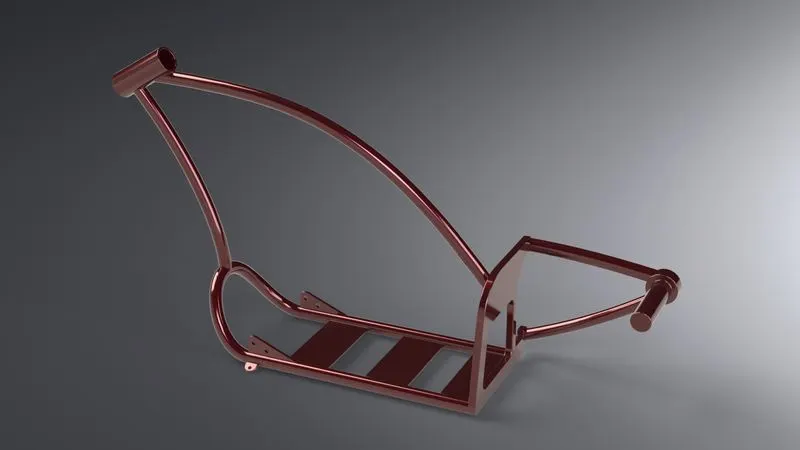
Fig. 10
Gas Tank: As the name suggests it is used to store fuel that then connects to the engine.This part is first modeled as surface part then thickness is added to it. I first started with making a reference plane and drawing two sketches on it which is later used as a path for surface sweeped to attain the basic geometry of the gas tank, now the edge is being trimmed. Next another plane is added with a front plane. Now with the help of boundary sweep feature the front face of the tank is being made and then i=entire body is being mirrored and joining them all together we get the entire gas tank structure by knit surface while finalising this there is extra feature to add material and make it a solid part. At the valley type structure I then make a seat by sketching and then extruding the surface and filleting the edges of the seat to give a rounded off look now with surface loft and knitting tools. A sketch is drawn at the face of the gas tank to cut the u section for the assembly of the tank with the chassis and all the sharp ends are then filleted a shell is created at the end to make it hollow. Again the base sienna color has been applied to the part and a grey cotton material is used for the seat the decals are used which will be discussed under rendering the part.
Fig. 11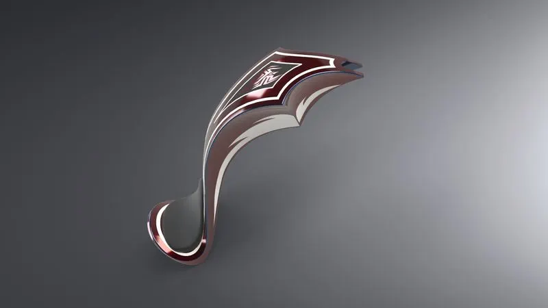
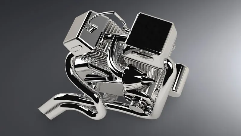
Engine and Exhaust System: An engine is most useful part of any motorcycle that helps any motorcycle to generate power.To create this a sketch is first made on the front plane and then extruded which acts as a base of motor and same sketch is used for different extruded boss to attain a proper shape next the upper curved part is extruded and then fillet is applied to all the edges.Next,on the back side of the base of motor two sketch followed by revolved features are made to make the arrangement between transmission belt and the spokes are made using the extrude and linear pattern around the circular region and same process is used on the other side of the extrude tool. The front of the cylindrical extrude is then cut out with the desired shape.The back of the motor the engine case and the top of the case is sketched and extruded one after the other and merged with the entire body a part from the engine body is cut out to make the fin which is linearly patterned throughout the surface as shown in the fig. and the fillets and chamfer are used . Now comes the designing of the exhaust pipe from the engine to do that two projected curve is made both the curves are then joined together to form a composite curve which is sweeped all the way from the starting face of the engine to the back according to the dimensions the same process is carried out for the second pipe and at last the wires are attached to the spark plug with two different sweeps. The material applied to the engine is chrome plate metal.
Fig. 12
II.Assembly
After creating each and every part of american chopper individual are imported in assembly workbench, lastly mates are applied to restrict their movement(Degree of freedom). Most widely used mates are coincidence,concentric,tangent,parallel which in solidworks comes with an individual category termed as “standard mates”.
Fig. 13
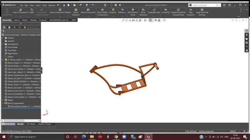
The chassis is the main frame and support of the whole assembly the first component which is called is the chassis of the chopper which then coincides with all planes of the assembly.
Fig. 14
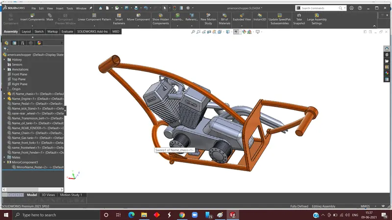
Second component which is imported is engine, firstly upper part of lower base part of chassis and bottom of engine is given a coincident relation to get the orientation we need then offset distance is given between engine base back side of foot of the engine and back side of the plates. Lastly To aligned it to the center midplane of both components is made to coincide with each other.
Fig. 15
Now the pedal is called and given a concentric and coincident relation to the hole that I created earlier in the process. For the opposite side pedal instead of importing it again I mirrored it with reference to the midplane.
Fig. 16
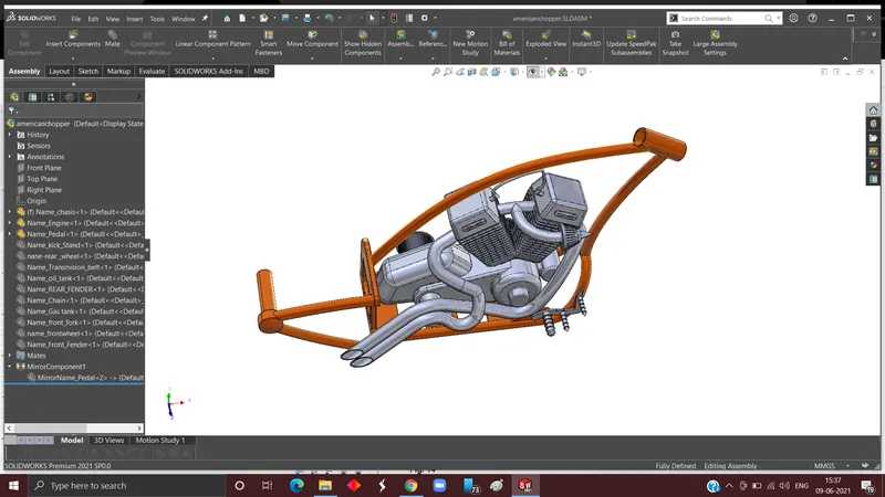
Next step is to import the side stand and make it concentric with the bracket I made it on chassis, to rotate the stand at a specified angle limit angle is specified to it for both clockwise and anticlockwise direction.
Fig. 17
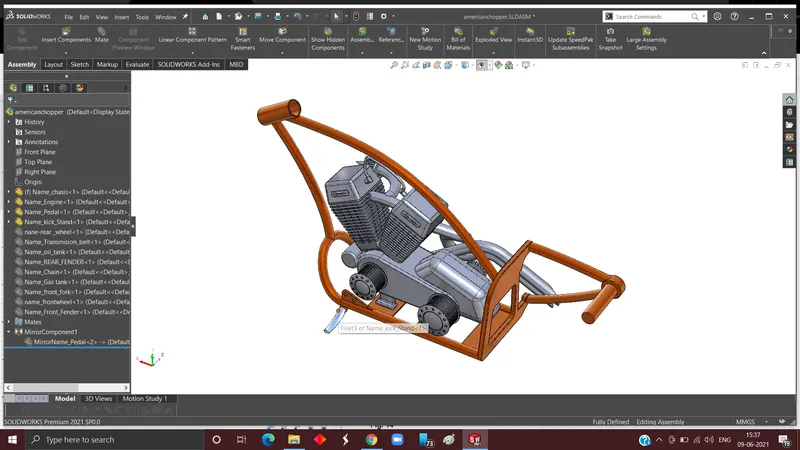
I begin next step by calling the transmission belt and make it concentric with the two motors that I earlier made.
Fig. 18
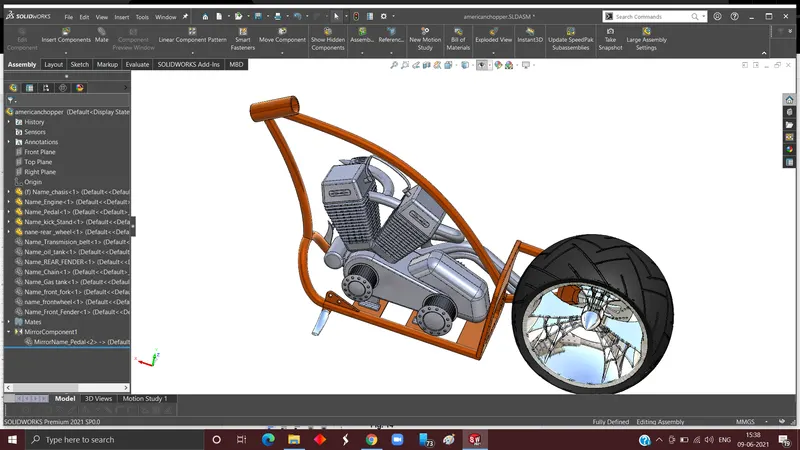
Next the oil tank comes into the picture and again coincidence mate is applied between engine edge and oil tank, following the same procedure mid planes of both components and coincident.
Fig. 19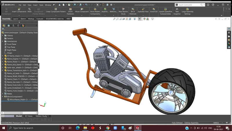
Now, rear wheel is imported and given a concentric relation with the extruded part I earlier made to attach rear wheel.
Fig. 20
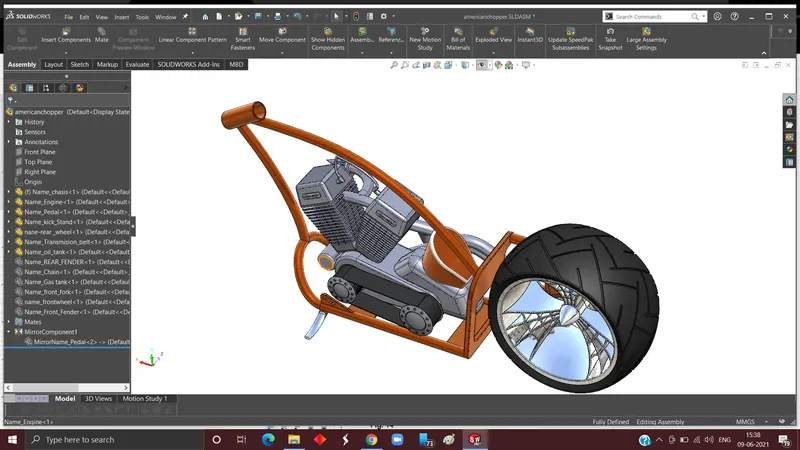
By proceeding from last step next task is to import rear fender and coincident it with the midplanes of both the planes. Now the front plane of rear wheel and rear fender is given a coincident relation. Lastly, the top plane of the fender and rear wheel are coincident.
Fig. 21
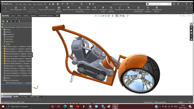
Now, chain is imported and given concentric relation with the shaft and sprocket, then coincident inner link with edge of the shaft.
Fig. 22
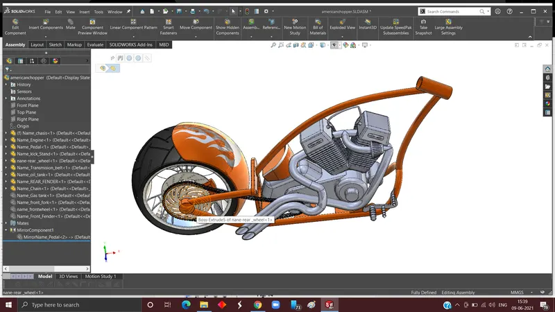
Front fork is imported and new reference is needed in middle of front fork to align it at the centre. Next concentric relation given to hollow cylindrical and boss of front fork then limit angle is given to turn the front fork left and right.
Fig. 23
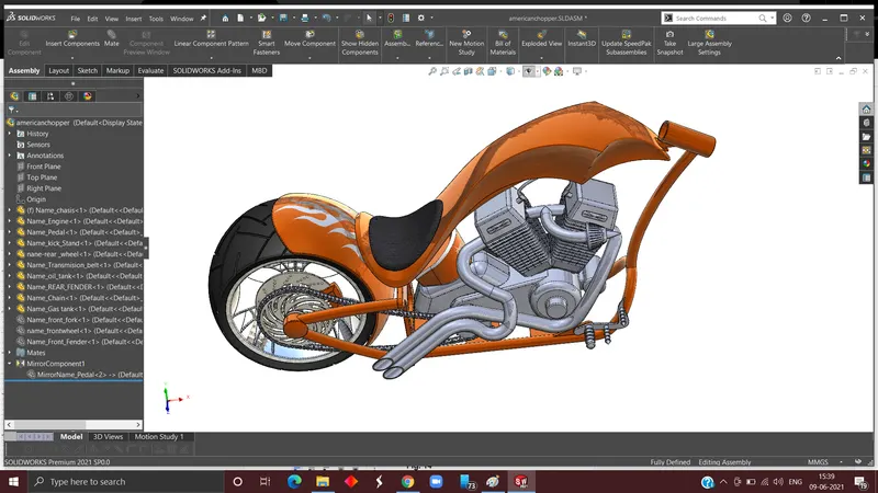
Next is to again call front wheel and make it concentric with the shaft I made on front fork. To aligned on the centre coincident relation is given to midplane of chassis and front wheel.
Fig. 24
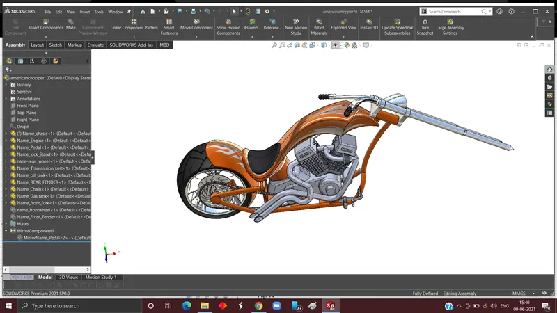
Now front fender is being imported and makde it coincident with all the planes of front wheel and front fender (top plane to the top)
Fig. 25
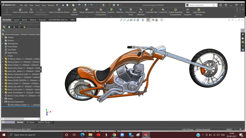
Last part of the assembly gas tank is imported and mates are given accordingly to fit in its right place.
Fig. 26
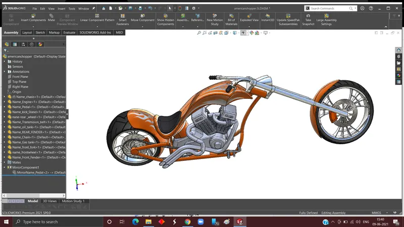
III.Rendering:
- Preprocessing: Before rendering we need to add some finishing touch like adding decals to various parts of the assembly. Another main task is to make sure that final assembly is touching the top plane. This is important because after rendering if tyre in not touching the ground so make it even more realistic I gave tangent relation to both tyre and top plane of assembly.
Fig. 27
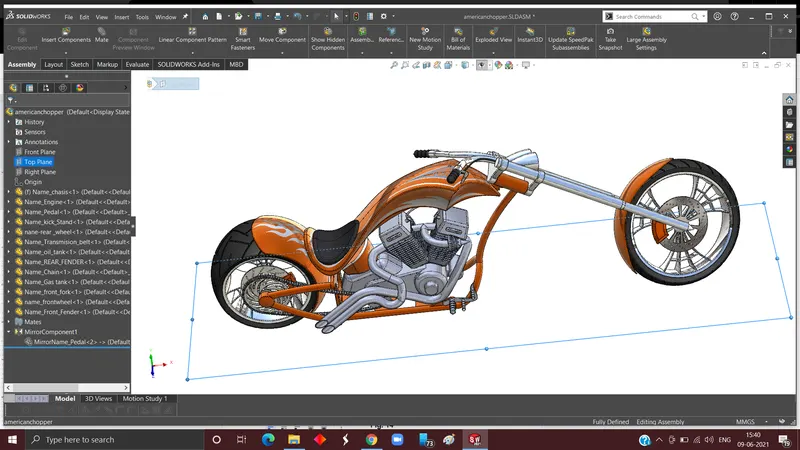
- Rendering: This is the main phase in which we add many features and make chopper more alive by adding things like background image so that we can visualize easily our final product in its actual environment. Now we need to adjust lights and camera so that model is visible and proper viewing also plays a important role.
Fig. 28
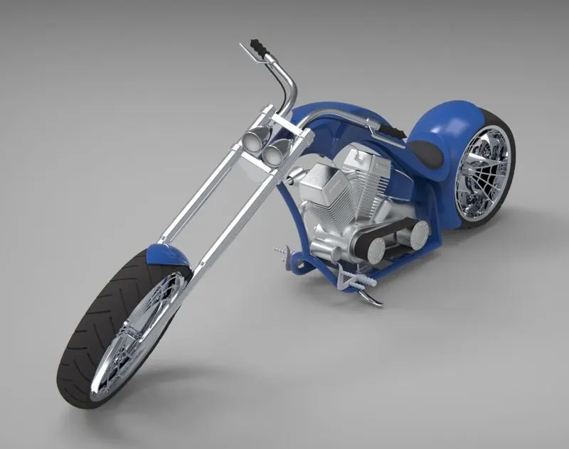
- Post Processing: This is the final step in which some adjustments if needed are done such as contrast, size and aspect ratio of the image.
Fig. 29
FInal Rendered images:
Fig. 30
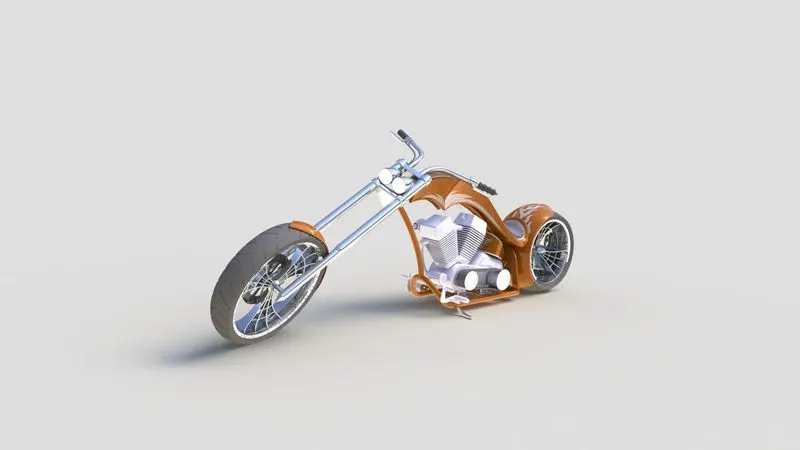
Fig. 31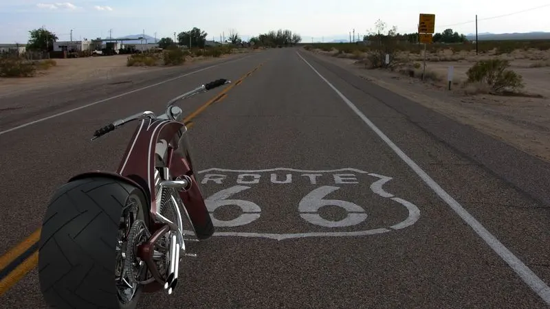
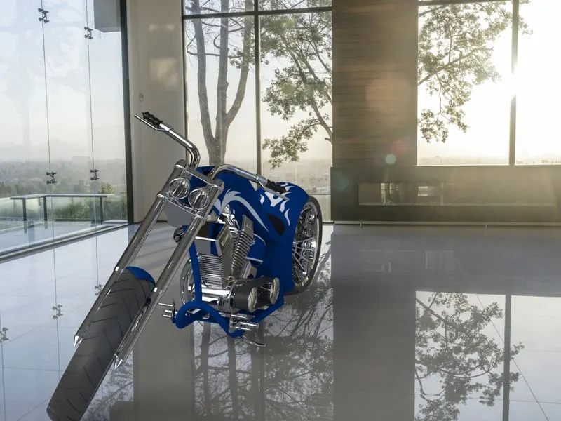
Fig. 32
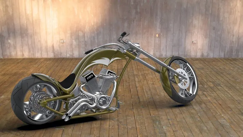
Fig. 33
Conclusion : Three dimension model is created by applying fundamental features on solidworks and then rendered in solidworks to visualize for better photo realistic images.