Advanced Sheet Metal Design Using NX Cad Challenge_5_Odd Shaped Enclosure
Tittle : To design and modelled odd shape enclosures using siemens NX-CAD
Objective :
1.) To understand the concept behind design
2.) To get familiar with NX-CAD sheet metal workbench
Introduction :
Sheet Metal : It is a comprehensive cold working process for sheet metal (Usually below 6mm).Thicknesses of this sheet can vary significantly extremely thin to the thicker sheets, thinner sheets are generally considered as foil or leaf and pieces thicker than 6 mm (0.25 in) are considered plate steel. There are many different metals that can be made into sheet metal, such as aluminium, brass, copper, steel, tin, nickel and titanium. Sheet metal is used in automobile and truck (lorry) bodies, airplane fuselages and wings, medical tables, roofs for buildings (architecture), and many other applications. Generally there are two types of region in any sheet metal are web and bend region. COMMON BENDING OPERATIONS GENERALLY used are Press brake forming, Air bending ,Roller bending , Beading,Flanging , Hemming , Roll forming , Stretch forming,Deep drawing.
NX-CAD Sheet metal Workbench : With Sheet metal CAD tools, you can apply standard values, such as material thicknesses and bend radii, based on industry or company best practices. With folding and unfolding capabilities, you can work with models at any stage of the fabrication process. Sheet metal parameters create accurate flat patterns for documentation and manufacturing.
Methodology :
To achieve a final product the methodology is followed is
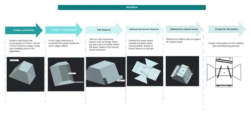
Features Used :
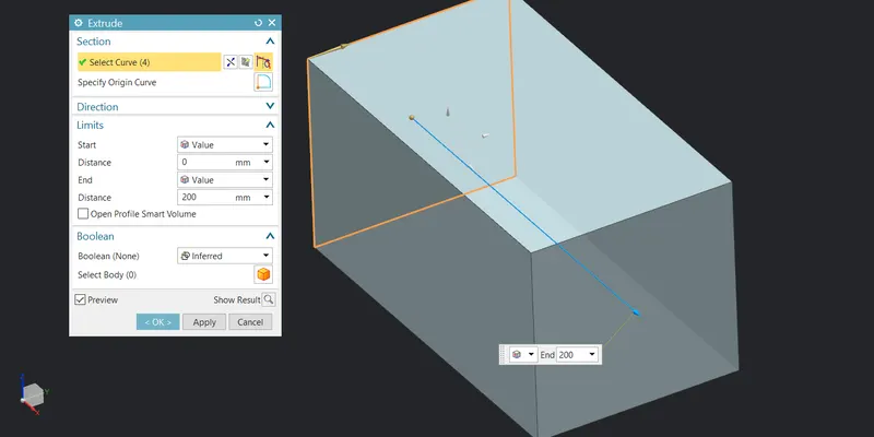
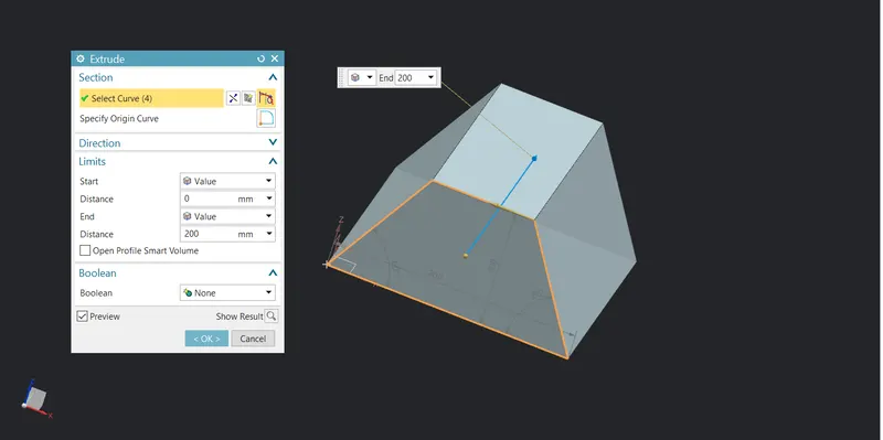
1.Extrude : It helps to convert a 2D profile into a 3D part by applying some material to the profile. Select any plane to sketch on it and then fully constraint the sketch before you exit to make sure that the sketch is fully closed profile. Then click on extrude and specify the extrude length to give thickness to the part.
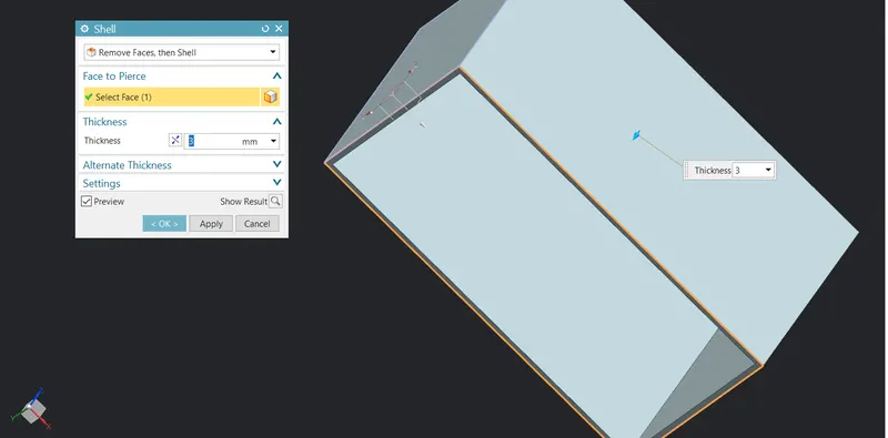
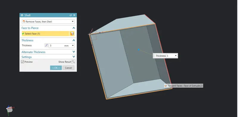
- Shell : Shell tool is the tool that helps to convert a solid body into a hollow part by applying some uniform thickness to the outer region of the geometry.To select the feature first in the application select modelling so that part features gets enabled. We can also flip the thickness for example if the thickness is added inside then we can change it to outside. Another useful feature of this command is that it can also delete the face and make it open from that deleted face.
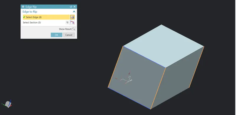
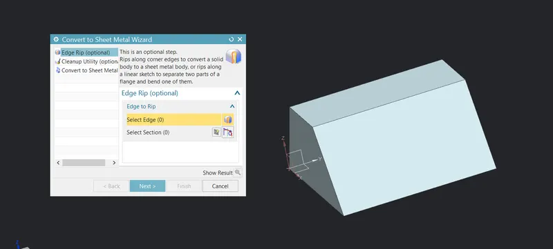
- Convert to sheet metal : As its name says it converts solid body into sheet metal. Important thing to note while using this feature is that with sheet-metal parameters the thickness of the sheet must be the same as the geometry and thickness must be uniform. It also adds bends to its edges and relief wherever it is applicable. Next thing we need to do is to rib edges so that it unbends the sheet.
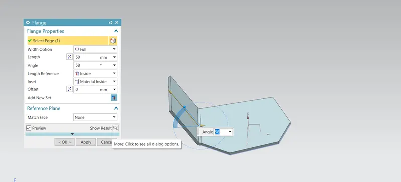
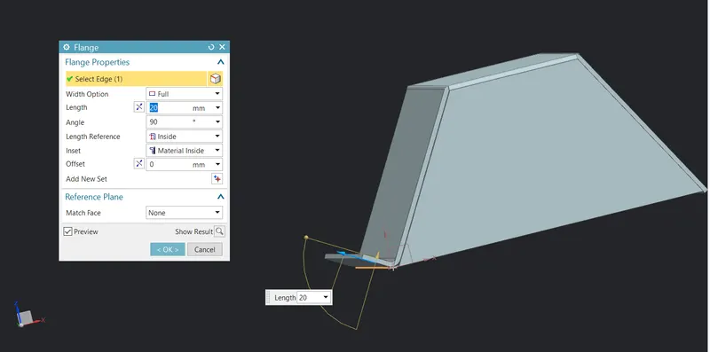
4.FLANGE: This feature adds a flange/wall on edge; it can be at an angle to a planar face and adds a bend between the two adjacent edges. First we need to select the edge then specify height and angle. Thickness in this feature is automatically assigned by its base plate and bend radius is also predefined in sheet metal parameters.If it is required to change bend radius we need to select on advance flange. For web region length of the flange and angle at which flange is situated for example if the flange is perpendicular to base plate then the angle we need to specify is 90 degree. There are many types of flange for example we can start the flange from the centre or we can give some offset values from both the ends and many more.
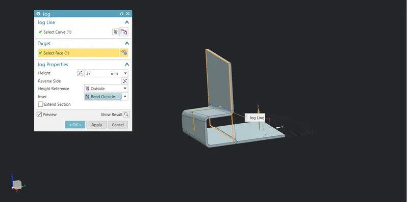
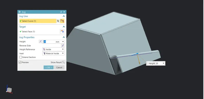
5.Jog : The Jog tool adds material to a sheet metal part by creating two bends from a sketched line. Some additional items to note about the Jog tool: The sketch must contain only one line. The line does not need to be horizontal or vertical. The bend line does not have to be the exact length of the faces you are bending.
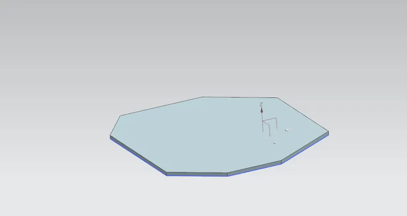
6.UNBEND: Usually this feature is used to create some additional features on the flanges by flattening a bend by first selecting the flat surface and then clicking on the bend region.
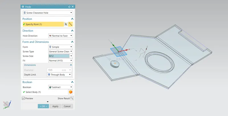
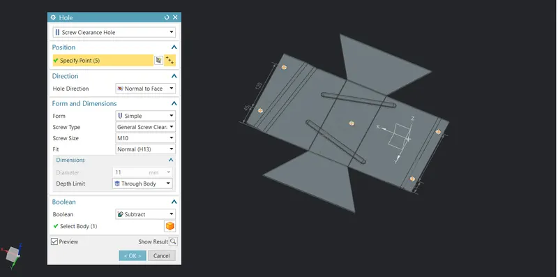
- Hole : First step is to locate the point by sketching on the plane the points are the centre of the hole. Then click on hole feature on the ribbon tab and select the point that you sketch earlier and give the diameter.
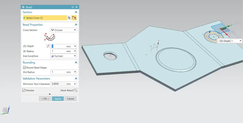
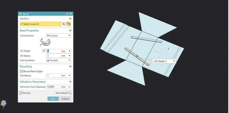
8.BEAD: It is a stamping tool that lifts a material along a counter of a sketch that simulates stamping a tool. In these parameters like depth of the stamping, radius of the stamping and die radius need to be specify correctly in order to work on this properly.
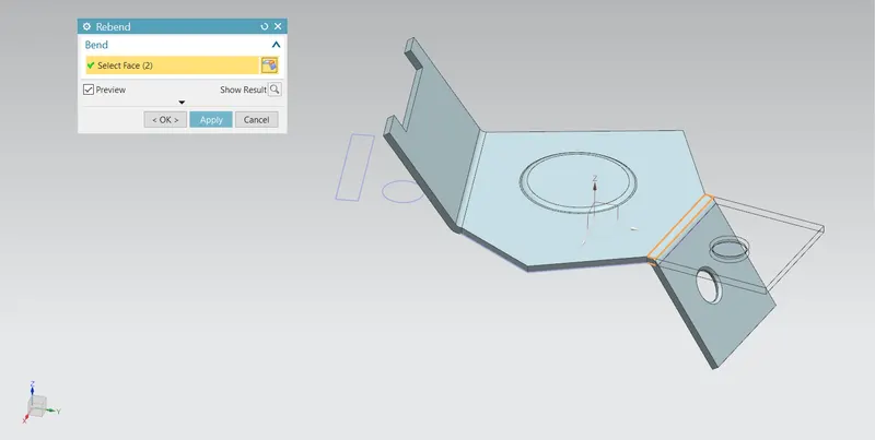
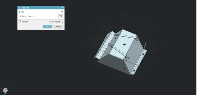
9.REBEND: Once all the features are done on the flanges then in order to rollback this command is used.It restores the bend by just selecting the bend region.
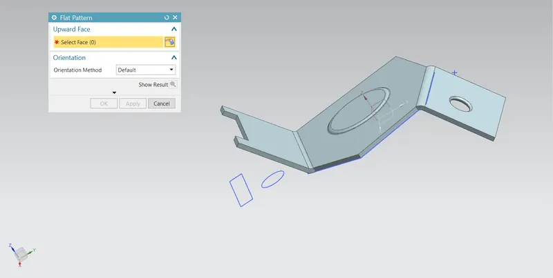
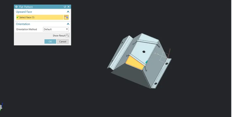
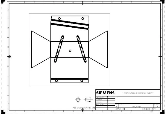
- FLAT PATTERN: Creates flat pattern feature from the formed sheet metal part. It is generally used for adding a flattern view of this sheet on the drafting environment.So that when the part is ready the manufacturer will have an idea of cutting the shape of sheet that needs to be cut and its dimensions.
Stepwise explanation :
Step1 :
Select any plane to begin the sketch with, draw a complete profile make sure that sketch is closed then define the dimensions of the part. Once the sketch is completed click on finish sketch and select extrude in the feature group under the more. After selecting one window pops up where we need to specify the thickness of the geometry.
Step 2 :
To select the shell tool first go to application menu there select modelling, there will be new group of commands located in which shell will be located to hollow the part from the inside, make sure that the thickness of the geometry is same as the thickness provided in the sheet metal parameter.
Step 3:
In this step part model is being converted into sheet metal geometry. For this select the sheetmetal wizard and click on the edges to rib this edges will have a gap between adjacent flanges. This feature also helps to and bend region on the edges once this process is done click on next here there is need to select on the base tab.
Step 4 :
Some additional features like flanges and jogging are being added to the part. Select the flange command on the ribbon toolbar above, in the pop up window specify the length and angle and make sure that the length reference is inside so that its maximum length does not get disturb and the material that is added to is inside. For the jog command select jog and click on the sketch tool and draw a line according to the application, then finish the sketch. For the jog command bar specify the height and make sure length returns inside and material is also inside.
Step 5 :
To add some additional features such as hole, bead cutouts etc the sheet metal part is being unbend to get its flatten view. To flatten the geometry click on unbend select the base tab and select on the all the bend region
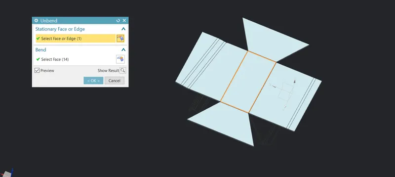
Steep 6:
Now the sheet is being flattened to apply some additional features like bead and hole. For the bead make a sketch of the profile that we want the material to lift and then click on finish the sketch. Click on bead tools located in the punch group. In the cross-section select circular and make sure that the radius is greater than the depth value. Next feature to be added is hole click on hole and then specify the point which is centre of the hole define the screw size and fit type which is generally normal and then click on “ok”.
Step 7 :
Now whole other features are added on the part so here we need to rebend the sheet. So, select the rebbend feature on the top and select the bend region that needs to be bent. And flat pattern the sheet to use unbend view while the drafting.
Step 9 :
In the file tab select the new part option and select drawing and define the sheet size of the drawing view, now select base view from there click on flat pattern view and specify the appropriate scale in which the whole flatten sheet must fit in.
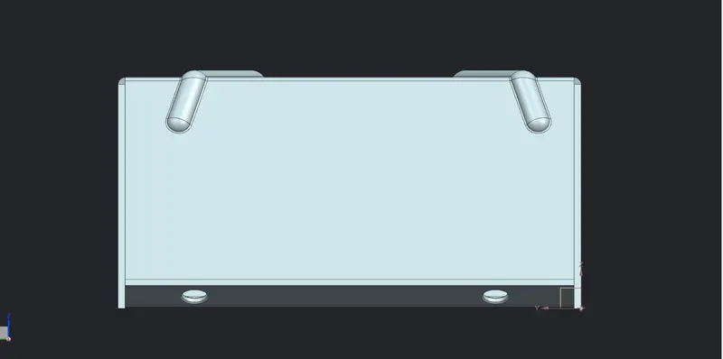
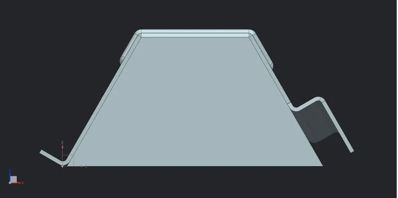
Standard View :
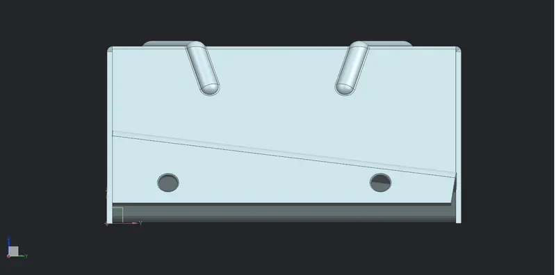
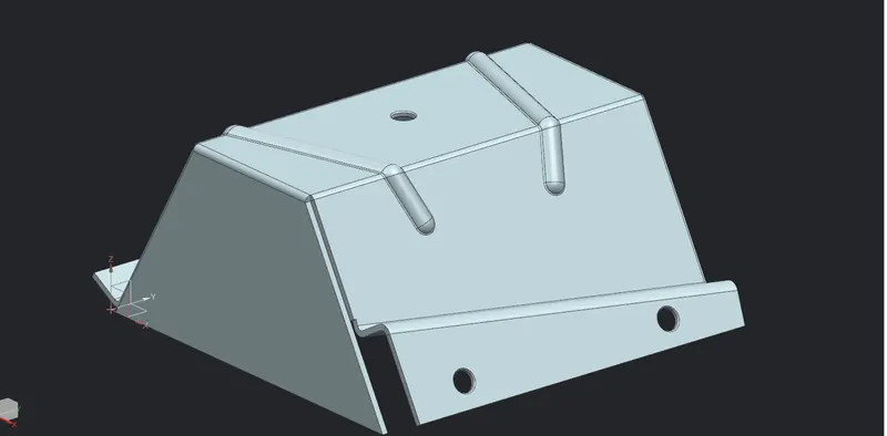
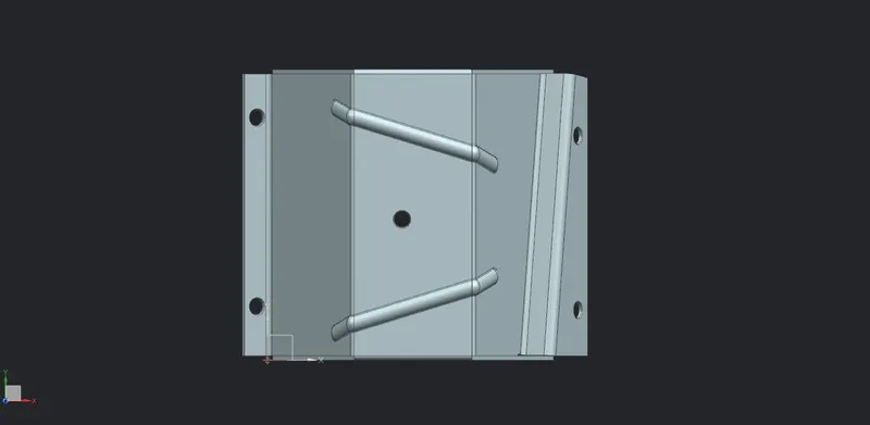
Conclusion : Hence the odd shape enclosure is being created in the sheetmetal